EP0145464A2 - Système de contrôle de véhicule - Google Patents
Système de contrôle de véhicule Download PDFInfo
- Publication number
- EP0145464A2 EP0145464A2 EP84308516A EP84308516A EP0145464A2 EP 0145464 A2 EP0145464 A2 EP 0145464A2 EP 84308516 A EP84308516 A EP 84308516A EP 84308516 A EP84308516 A EP 84308516A EP 0145464 A2 EP0145464 A2 EP 0145464A2
- Authority
- EP
- European Patent Office
- Prior art keywords
- transponder
- vehicle
- transponders
- information concerning
- train
- Prior art date
- Legal status (The legal status is an assumption and is not a legal conclusion. Google has not performed a legal analysis and makes no representation as to the accuracy of the status listed.)
- Ceased
Links
Images

Classifications
-
- F—MECHANICAL ENGINEERING; LIGHTING; HEATING; WEAPONS; BLASTING
- F41—WEAPONS
- F41G—WEAPON SIGHTS; AIMING
- F41G1/00—Sighting devices
- F41G1/54—Devices for testing or checking ; Tools for adjustment of sights
-
- B—PERFORMING OPERATIONS; TRANSPORTING
- B61—RAILWAYS
- B61L—GUIDING RAILWAY TRAFFIC; ENSURING THE SAFETY OF RAILWAY TRAFFIC
- B61L3/00—Devices along the route for controlling devices on the vehicle or train, e.g. to release brake or to operate a warning signal
- B61L3/02—Devices along the route for controlling devices on the vehicle or train, e.g. to release brake or to operate a warning signal at selected places along the route, e.g. intermittent control simultaneous mechanical and electrical control
- B61L3/08—Devices along the route for controlling devices on the vehicle or train, e.g. to release brake or to operate a warning signal at selected places along the route, e.g. intermittent control simultaneous mechanical and electrical control controlling electrically
- B61L3/12—Devices along the route for controlling devices on the vehicle or train, e.g. to release brake or to operate a warning signal at selected places along the route, e.g. intermittent control simultaneous mechanical and electrical control controlling electrically using magnetic or electrostatic induction; using radio waves
- B61L3/125—Devices along the route for controlling devices on the vehicle or train, e.g. to release brake or to operate a warning signal at selected places along the route, e.g. intermittent control simultaneous mechanical and electrical control controlling electrically using magnetic or electrostatic induction; using radio waves using short-range radio transmission
-
- B—PERFORMING OPERATIONS; TRANSPORTING
- B61—RAILWAYS
- B61L—GUIDING RAILWAY TRAFFIC; ENSURING THE SAFETY OF RAILWAY TRAFFIC
- B61L3/00—Devices along the route for controlling devices on the vehicle or train, e.g. to release brake or to operate a warning signal
- B61L3/02—Devices along the route for controlling devices on the vehicle or train, e.g. to release brake or to operate a warning signal at selected places along the route, e.g. intermittent control simultaneous mechanical and electrical control
- B61L3/08—Devices along the route for controlling devices on the vehicle or train, e.g. to release brake or to operate a warning signal at selected places along the route, e.g. intermittent control simultaneous mechanical and electrical control controlling electrically
- B61L3/12—Devices along the route for controlling devices on the vehicle or train, e.g. to release brake or to operate a warning signal at selected places along the route, e.g. intermittent control simultaneous mechanical and electrical control controlling electrically using magnetic or electrostatic induction; using radio waves
- B61L3/121—Devices along the route for controlling devices on the vehicle or train, e.g. to release brake or to operate a warning signal at selected places along the route, e.g. intermittent control simultaneous mechanical and electrical control controlling electrically using magnetic or electrostatic induction; using radio waves using magnetic induction
Definitions
- the invention relates to a vehicle control system for controlling and/or monitoring the passage of vehicles constrained to move along a fixed path, particularly a railway.
- the invention is useful for traffic control by radio signalling of single and multiple railway tracks for both unidirectional and bi-directional running, for example in a system of radio token working.
- Transponders mounted at fixed positions along the path play an essential roll in such systems
- active transponders supplied with coded electrical signals from a central control office co-operate with sensors on the vehicle to pass to the vehicle essential information.
- transponders may replace coloured light signals e.g. the red, amber and green aspect lamps which are used to govern the progress of a train and to maintain a predetermined minimum headway. Transponders may also provide the train with maximum safe speed limit and track gradient information for example. The transponders are also used in conjunction with the train safety equipment, i.e. the automatic train protection system. If a train receives no information from a transponder or if one of more transponders in its path are inoperative, it is arranged, in such circumstances, that the emergency braking system shall operate.
- the train safety equipment i.e. the automatic train protection system
- transponders In arrangements of the type referred to it is known to place the transponders at predetermined fixed distances apart or at regular intervals and to measure the distance travelled by the train from speed information derived from tachometers. A transponder may also be arranged to declare the distance to the next transponder for on-board comparison. These arrangements necessitate in-built tolerance to accommodate errors caused by, for instance, wheel-slide and wheel-spin and, being critical components, high reliability is demanded of the tachometers. The integrity of a system can be compromised by the necessity to accommodate errors.
- the present invention seeks to provide a simpler and more flexible arrangement whilst providing a system having a level of integrity and safety at least as high as that of known systems.
- a vehicle control system for a vehicle constrained to move along fixed pathways comprising
- the positions of the transponders are staggered along the path, and the vehicle has means for storing the information concerning the next transponders, means for comparing information concerning a sensed transponder and said stored information, and means responsive to lack of corresondence in said comparison to exercise a safety function, for example, to bring into effect an emergency braking system.
- transponders as used herein, is to be construed as including active units which continuously transmit their signals or transmit when interrogated, passive units which act as reflectors, for example, devices which are adapted to resonate when an appropriate form of radiation is incident thereon?
- the term may also include mechanical devices mounted on a track bed or even members attached to the running rails of a railway track.
- transponders are grouped together to mark the boundary between signalling sections and detection equipment carried by the vehicle is able to discriminate between the individual transponders in a group.
- the distinguishing characteristic of the individual transponders in this group is that they are staggered on alternate sides of the track, i.e.the first to the left and the second to the right and the train is equipped with left and right sensors, a first of which responds only to left-side transponders and a second of which responds only to right-side transponders.
- the transponders may operate at different frequencies and the train sensors are frequency selective in respect of the left or the right-side-irequencies exclusively. Other arrangements are also possible.
- the vehicle detection equipment includes means which is provided with information relating to the transponders so that, having successfully located one transponder it is then provided with information concerning the next transponder, in particular its distinguishing feature. If the wrong type or identity of transponder is detected next an appropriate safety procedcure can be initiated, the emergency braking system can be actuated. Safety is maintained in the event of one transponder or detector failing or not being sensed because the next transponder which is located will be "wrong".
- each transponder should be sensed by each passing train all transponders and the train carried detectors are constantly being proved as a train passes through each signalling section, thus faults in the system are detected without unnecessary delay and all equipment is continuously checked so that the incidence of more than one fault at any time will be very rare.
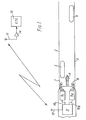
- a train is constrained to move along a fixed path comprising rails 2 and 3, and moves in the direction of travel indicated by arrow 4.
- transponders At positions along the path there are located transponders, in the example being described these are passive transponders, comprising inductive loops 5 and 6 laid in the path of the vehicle on or buried in the track bed ballast.
- the train 1 carries a pair of sensing antennae 7 and 8 which are carried to the left and right side respectively of the front of the vehicle in a position in which they will inductively couple with the loops 5 and 6. Signals from the antennae 7 and 8 are supplied respectively to amplifying and detection equipment 9L and 9R carried on board the train.
- the sensed outputs 10L and 10R from this equipment are supplied to train control equipment, generally indicated at 11, which includes a radio receiver/transmitter and communications antennae 12, via which the train establishes a radio link through the communications antennae 13 and radio transmitter receiver 14 of a central traffic equipment 15.
- the vehicle equipment includes the sensing means for sensing the particular characteristic of the transponders and, where appropriate, also includes apparatus for transmitting a suitable signal to a transponder either for the purpose of triggering a response from an active transponder or providing the energising signal for a passive transponder.
- the equipment also includes a receiver for communications from the central office for information concerning a transponder, and means for decoding the information, temporary storage means for storing the information received and comparison means for comparing the sensed information relating to a transponder encountered by the vehicle with the stored information relating to the transponder expected to be encountered.
- the comparison means Connected to the comparison means is further apparatus responsive to the result of the comparison and which is operative to trigger a transmission to the central office, in the event of the two sets of information corresponding, in order to receive fresh information concerning the next expected transponder.
- the receiver is connected to means for loading the new information into said temporary storage memory means reading for the next comparison operation, the old information being erased from the memory in the same operation.
- Further apparatus is provided, operative in the event of lack of correspondence in the comparison process, to bring into operation a safety function for example an application of the emergency braking system.
- alternative safety functions may be instituted. Such as a warning given to a train driver which requires some action or, at least acknowledgement upon his part.
- the transponder loops 5 and 6 are laid in pairs, with the first encountered (loop 5) on the left side of the track in the direction of travel 4 and the second encountered (loop 6) on the right side of the track.
- These loops are passive, that is they have no active power source but are arranged to return a uniquely coded signal when interrogated by the corresponding ones of the antennae 7 and 8 on the corresponding side of train 1.
- the train 1 will maintain its normal progress. However, should at any time a transponder loop not be encountered on the expected side the control equipment 11 is arranged to resond by energising the train emergency braking equipment. Further progress will then depend upon the implementation of special emergency procedures.
- Fig. 2 illustrates how the invention is used to mark the limit of a signalling section containing a set of points, generally indicated at reference 20, which give access to and from a branch line 21.
- the boundaries of the signalling section are marked by transducer loops 5 and 6 on the main line on the side approached in the directions of arrow 4, by transducer loops 22 and 23 on the branch line and further loops 24 and 25 at the section on the main line.
- the central equipment 15 will provide the train with the code and position of transducer loop 23, and then subsequently transducer loop 22. If the train successfully transmits the code of loop 23 it will be logged as having successfully passed through the points of junction 20 onto the branch line 21. If, instead, the train senses the code loop 24 the automatic train protection equipment 11 will immediately note the discrepancy and energise the train emergency braking system. At the same time the train will transmit the code of the detected transponder loop 24 to the central control 15 which will note the location of the train and bring into operation appropriate emergency procedures.
- transponder loops are of the passive type, that is that contain no power source and are unable to change state and convey to a train anything other than static information.
- at least some of the transponder loops may be of active type and be able to transmit selected information to a train for signalling purposes.
- all signalling information is provided to a train by means of the radio communication link.
- Any other form of transducer may be used in places of the passive loops of the described arrangement.
- the transducers are used to mark track section boundaries, as described to mark the ends of a short points section, which for example may be found at the entrance and exit of a passing loop.
- the transducers may be used to mark the boundaries between track sections, the boundary limits of cross-overs, and so on.
- the transponders may be used individually at each location, or alternatively in groups, e.g. as a pair, the members of which are staggered as described above.
Landscapes
- Engineering & Computer Science (AREA)
- Mechanical Engineering (AREA)
- Physics & Mathematics (AREA)
- Optics & Photonics (AREA)
- General Engineering & Computer Science (AREA)
- Train Traffic Observation, Control, And Security (AREA)
- Electric Propulsion And Braking For Vehicles (AREA)
Applications Claiming Priority (2)
| Application Number | Priority Date | Filing Date | Title |
|---|---|---|---|
| GB8332919 | 1983-12-09 | ||
| GB838332919A GB8332919D0 (en) | 1983-12-09 | 1983-12-09 | Vehicle control system |
Publications (2)
| Publication Number | Publication Date |
|---|---|
| EP0145464A2 true EP0145464A2 (fr) | 1985-06-19 |
| EP0145464A3 EP0145464A3 (fr) | 1987-04-22 |
Family
ID=10553087
Family Applications (1)
| Application Number | Title | Priority Date | Filing Date |
|---|---|---|---|
| EP84308516A Ceased EP0145464A3 (fr) | 1983-12-09 | 1984-12-07 | Système de contrôle de véhicule |
Country Status (13)
| Country | Link |
|---|---|
| US (1) | US4768740A (fr) |
| EP (1) | EP0145464A3 (fr) |
| JP (1) | JPS60139570A (fr) |
| KR (1) | KR850004732A (fr) |
| AU (1) | AU575278B2 (fr) |
| BR (1) | BR8406279A (fr) |
| CA (1) | CA1244927A (fr) |
| DK (1) | DK586084A (fr) |
| ES (1) | ES8507397A1 (fr) |
| GB (2) | GB8332919D0 (fr) |
| NZ (1) | NZ210411A (fr) |
| ZA (1) | ZA849295B (fr) |
| ZW (1) | ZW20084A1 (fr) |
Cited By (3)
| Publication number | Priority date | Publication date | Assignee | Title |
|---|---|---|---|---|
| NL8700674A (nl) * | 1986-04-08 | 1987-11-02 | Gen Signal Corp | Op radio gebaseerd spoorwegsignalerings- en verkeersbesturingsstelsel. |
| EP0257909A3 (en) * | 1986-08-16 | 1990-05-02 | Westinghouse Brake And Signal Holdings Limited | Communicating vital control signals |
| WO2008034684A3 (fr) * | 2006-09-19 | 2008-05-22 | Siemens Ag | Système et procédé de détermination de la trajectoire de circulation et/ou de la vitesse de véhicules, en particulier de commande de la marche de trains |
Families Citing this family (34)
| Publication number | Priority date | Publication date | Assignee | Title |
|---|---|---|---|---|
| JPS6460586A (en) * | 1987-08-26 | 1989-03-07 | Mitsubishi Electric Corp | Controller for elevator |
| FR2644420B1 (fr) * | 1989-03-17 | 1991-07-05 | Aigle Azur Concept | Systeme de commande de la progression de plusieurs convois ferroviaires sur un reseau |
| US5129605A (en) * | 1990-09-17 | 1992-07-14 | Rockwell International Corporation | Rail vehicle positioning system |
| FR2672026B1 (fr) * | 1991-01-24 | 1993-05-21 | Aigle Azur Concept | Dispositif de controle automatique de vitesse d'arret, et d'aide a la conduite du vehicule, notamment ferroviaire. |
| GB9202830D0 (en) * | 1992-02-11 | 1992-03-25 | Westinghouse Brake & Signal | A railway signalling system |
| US5340062A (en) * | 1992-08-13 | 1994-08-23 | Harmon Industries, Inc. | Train control system integrating dynamic and fixed data |
| US5332180A (en) * | 1992-12-28 | 1994-07-26 | Union Switch & Signal Inc. | Traffic control system utilizing on-board vehicle information measurement apparatus |
| US7397363B2 (en) * | 1993-06-08 | 2008-07-08 | Raymond Anthony Joao | Control and/or monitoring apparatus and method |
| SE515499C2 (sv) * | 1993-11-08 | 2001-08-13 | Telia Ab | Anordning för att möjliggöra kommunikation och positionering i styranläggning |
| US5511749A (en) | 1994-04-01 | 1996-04-30 | Canac International, Inc. | Remote control system for a locomotive |
| US5533695A (en) * | 1994-08-19 | 1996-07-09 | Harmon Industries, Inc. | Incremental train control system |
| US10011247B2 (en) | 1996-03-27 | 2018-07-03 | Gtj Ventures, Llc | Control, monitoring and/or security apparatus and method |
| US7253731B2 (en) | 2001-01-23 | 2007-08-07 | Raymond Anthony Joao | Apparatus and method for providing shipment information |
| US6044698A (en) * | 1996-04-01 | 2000-04-04 | Cairo Systems, Inc. | Method and apparatus including accelerometer and tilt sensor for detecting railway anomalies |
| DE19630575A1 (de) * | 1996-07-30 | 1998-02-05 | Sel Alcatel Ag | System zur semikontinuierlichen Steuerung von spurgeführten Fahrzeugen |
| US5803411A (en) * | 1996-10-21 | 1998-09-08 | Abb Daimler-Benz Transportation (North America) Inc. | Method and apparatus for initializing an automated train control system |
| US9075136B1 (en) | 1998-03-04 | 2015-07-07 | Gtj Ventures, Llc | Vehicle operator and/or occupant information apparatus and method |
| WO1999051479A1 (fr) * | 1998-03-24 | 1999-10-14 | Tss Traffic Supervision Systems A/S | Procede de commande et de positionnement d'un objet mobile, et systeme de realisation de ce procede |
| AU8931601A (en) * | 2000-04-06 | 2001-10-23 | Central Research Laboratories Limited | An information system for a railway |
| US6631873B2 (en) * | 2000-05-12 | 2003-10-14 | Glen T. Fisher | Protection device to prevent train incursions into a forbidden area |
| WO2002059635A2 (fr) | 2001-01-10 | 2002-08-01 | Lockheed Martin Corporation | Systeme et procede de localisation de trains |
| US10562492B2 (en) | 2002-05-01 | 2020-02-18 | Gtj Ventures, Llc | Control, monitoring and/or security apparatus and method |
| US7792089B2 (en) * | 2002-07-31 | 2010-09-07 | Cattron-Theimeg, Inc. | System and method for wireless remote control of locomotives |
| ITTO20030978A1 (it) * | 2003-12-05 | 2005-06-06 | Ansaldo Segnalamento Ferroviario S P A | Boa (balise) per segnalazione ferroviaria e metodo di realizzazione della boa stessa. |
| JP4087786B2 (ja) * | 2003-12-19 | 2008-05-21 | 株式会社日立製作所 | 列車位置検知方法 |
| DE102007031138A1 (de) * | 2007-06-29 | 2009-01-02 | Siemens Ag | Verfahren und Anordnung zum Betreiben einer Eisenbahnstrecke |
| DE102007038819B4 (de) * | 2007-08-16 | 2015-01-22 | Deutsches Zentrum für Luft- und Raumfahrt e.V. | Vorrichtung zur fahrzeugseitigen Gleisfrei- und/oder Gleisbesetztmeldung |
| JP2009053937A (ja) * | 2007-08-27 | 2009-03-12 | Asyst Technologies Japan Inc | 搬送システム、及び搬送システムの制御方法 |
| US8423240B2 (en) * | 2008-06-30 | 2013-04-16 | International Electronic Machines Corporation | Wireless railroad monitoring |
| US8576114B2 (en) * | 2011-06-24 | 2013-11-05 | Thales Canada Inc. | Location of a transponder center point |
| US9227641B2 (en) | 2013-05-03 | 2016-01-05 | Thales Canada Inc | Vehicle position determining system and method of using the same |
| US10546441B2 (en) | 2013-06-04 | 2020-01-28 | Raymond Anthony Joao | Control, monitoring, and/or security, apparatus and method for premises, vehicles, and/or articles |
| US9606224B2 (en) * | 2014-01-14 | 2017-03-28 | Alstom Transport Technologies | Systems and methods for vehicle position detection |
| JP6767941B2 (ja) * | 2017-07-18 | 2020-10-14 | 株式会社京三製作所 | 車上装置及び地上装置 |
Family Cites Families (22)
| Publication number | Priority date | Publication date | Assignee | Title |
|---|---|---|---|---|
| DE928470C (de) * | 1953-03-21 | 1955-06-02 | Siemens Ag | Zugbeeinflussung mittels an der Strecke angeordneter Beeinflussungspunkte |
| US2948234A (en) * | 1957-09-30 | 1960-08-09 | Gen Railway Signal Co | Remote control organization for a locomotive |
| US3072785A (en) * | 1960-04-21 | 1963-01-08 | Gen Railway Signal Co | Remote control system for vehicles |
| US3250914A (en) * | 1961-11-02 | 1966-05-10 | Gen Signal Corp | Zone control system |
| US3281779A (en) * | 1962-12-31 | 1966-10-25 | Bunker Ramo | Position detecting means for vehicles |
| DE1232879B (de) * | 1964-07-11 | 1967-01-19 | Beteiligungs & Patentverw Gmbh | Selbsttaetige, wegabhaengige Steuerung fuer ein auf Schienen verfahrbares Transportgeraet |
| US3772640A (en) * | 1971-04-01 | 1973-11-13 | Gen Signal Corp | Vehicle control system with vehicle location error checking means |
| DE2124089C3 (de) * | 1971-05-14 | 1983-11-03 | Siemens AG, 1000 Berlin und 8000 München | Einrichtung bei Schienenbahnen zur Informationsübertragung von der Strecke auf die Fahrzeuge |
| US3933099A (en) * | 1971-07-29 | 1976-01-20 | H. Jungheinrich & Co. | Vehicle control apparatus for a closed transporting system |
| US3787679A (en) * | 1972-01-26 | 1974-01-22 | British Railways Board | Train communication system |
| GB1390225A (en) * | 1972-06-14 | 1975-04-09 | British Railways Board | Vehicle control system |
| GB1469510A (en) * | 1973-06-21 | 1977-04-06 | British Railways Board | Train control |
| GB1501372A (en) * | 1973-11-27 | 1978-02-15 | Hawker Siddeley Dynamics Ltd | Identifying location of vehicles |
| SE384477B (sv) * | 1974-08-16 | 1976-05-10 | Philips Svenska Ab | Sett och anordning for att astadkomma synkronisering i en informationsoverforingsanleggning innefattande en fragestation och ett svarsdon |
| US4038653A (en) * | 1976-03-16 | 1977-07-26 | International Standard Electric Corporation | Train position indicator |
| DE2643760A1 (de) * | 1976-09-29 | 1978-03-30 | Licentia Gmbh | Verfahren zur erhoehung der genauigkeit bei der bestimmung des fahrweges trassengebundener fahrzeuge |
| JPS5513582A (en) * | 1978-07-13 | 1980-01-30 | Sanyo Electric Co Ltd | Color television receiver |
| DE2854339A1 (de) * | 1978-12-15 | 1980-06-26 | Siemens Ag | Einrichtung zum uebertragen von streckeninformationen an ein spurgebundenes fahrzeug |
| US4284160A (en) * | 1979-03-19 | 1981-08-18 | Barrett Electronics Corporation | Vehicle guidance system employing radio blocking |
| US4361202A (en) * | 1979-06-15 | 1982-11-30 | Michael Minovitch | Automated road transportation system |
| DE3040137C2 (de) * | 1980-10-24 | 1987-01-29 | Standard Elektrik Lorenz Ag, 7000 Stuttgart | Punktförmige Einrichtung zur Übertragung von Information zwischen einer Trasse und auf dieser geführten Fahrzeugen |
| DE3513384A1 (de) * | 1985-04-15 | 1986-11-06 | Moeller automation GmbH, 5303 Bornheim | Profilsystem zum bau von montageeinrichtungen, stuetzkonstruktionen und transportbaendern |
-
1983
- 1983-12-09 GB GB838332919A patent/GB8332919D0/en active Pending
-
1984
- 1984-11-28 ZA ZA849295A patent/ZA849295B/xx unknown
- 1984-12-03 NZ NZ210411A patent/NZ210411A/xx unknown
- 1984-12-05 ZW ZW200/84A patent/ZW20084A1/xx unknown
- 1984-12-06 KR KR1019840007719A patent/KR850004732A/ko not_active Withdrawn
- 1984-12-07 GB GB08430937A patent/GB2151385B/en not_active Expired
- 1984-12-07 EP EP84308516A patent/EP0145464A3/fr not_active Ceased
- 1984-12-07 ES ES538395A patent/ES8507397A1/es not_active Expired
- 1984-12-07 DK DK586084A patent/DK586084A/da unknown
- 1984-12-07 AU AU36430/84A patent/AU575278B2/en not_active Ceased
- 1984-12-07 BR BR8406279A patent/BR8406279A/pt unknown
- 1984-12-07 CA CA000469566A patent/CA1244927A/fr not_active Expired
- 1984-12-08 JP JP59259854A patent/JPS60139570A/ja active Pending
-
1986
- 1986-09-02 US US06/902,996 patent/US4768740A/en not_active Expired - Fee Related
Cited By (3)
| Publication number | Priority date | Publication date | Assignee | Title |
|---|---|---|---|---|
| NL8700674A (nl) * | 1986-04-08 | 1987-11-02 | Gen Signal Corp | Op radio gebaseerd spoorwegsignalerings- en verkeersbesturingsstelsel. |
| EP0257909A3 (en) * | 1986-08-16 | 1990-05-02 | Westinghouse Brake And Signal Holdings Limited | Communicating vital control signals |
| WO2008034684A3 (fr) * | 2006-09-19 | 2008-05-22 | Siemens Ag | Système et procédé de détermination de la trajectoire de circulation et/ou de la vitesse de véhicules, en particulier de commande de la marche de trains |
Also Published As
| Publication number | Publication date |
|---|---|
| GB2151385B (en) | 1987-06-24 |
| CA1244927A (fr) | 1988-11-15 |
| ZA849295B (en) | 1985-07-31 |
| GB8430937D0 (en) | 1985-01-16 |
| DK586084D0 (da) | 1984-12-07 |
| AU3643084A (en) | 1985-06-13 |
| DK586084A (da) | 1985-06-10 |
| ES538395A0 (es) | 1985-09-01 |
| GB2151385A (en) | 1985-07-17 |
| ES8507397A1 (es) | 1985-09-01 |
| GB8332919D0 (en) | 1984-01-18 |
| ZW20084A1 (en) | 1986-07-02 |
| BR8406279A (pt) | 1985-10-01 |
| NZ210411A (en) | 1988-09-29 |
| KR850004732A (ko) | 1985-07-27 |
| JPS60139570A (ja) | 1985-07-24 |
| EP0145464A3 (fr) | 1987-04-22 |
| US4768740A (en) | 1988-09-06 |
| AU575278B2 (en) | 1988-07-21 |
Similar Documents
| Publication | Publication Date | Title |
|---|---|---|
| EP0145464A2 (fr) | Système de contrôle de véhicule | |
| US5369591A (en) | Vehicle longitudinal control and collision avoidance system for an automated highway system | |
| JP4087786B2 (ja) | 列車位置検知方法 | |
| JP4999752B2 (ja) | 無線基地局停止時における列車間隔制御 | |
| JP6846208B2 (ja) | 光ケーブルを利用した鉄道制御システム | |
| KR20110044203A (ko) | 피유도 차량의 이동 특성들을 결정하기 위한 시스템 | |
| GB2189066A (en) | Railway radio signalling | |
| EP0341827A2 (fr) | Calcul de la longueur d'un véhicule de chemin de fer ou d'un train ou d'un train de tel véhicule | |
| SE441315B (sv) | Anordning for att indikera viss nerhet mellan rorliga fordon | |
| KR102132362B1 (ko) | 차상제어장치와 연동되는 철도신호장치 | |
| US3787679A (en) | Train communication system | |
| JPS60257703A (ja) | 車両防御システム | |
| CN111163991A (zh) | 列车控制系统 | |
| JP6491948B2 (ja) | 電気車位置検知システム | |
| KR102498585B1 (ko) | 철도차량의 안전사고를 예방하는 철도신호 시스템 | |
| US3991958A (en) | Magnetically actuated registration circuitry for a vehicle control system | |
| KR101026149B1 (ko) | 자기부상열차의 속도검지장치 | |
| EP0233017B1 (fr) | Opération automatique de véhicule de train | |
| JP3830312B2 (ja) | 列車検知装置 | |
| JP3878749B2 (ja) | 通行異常検知装置 | |
| JP3286122B2 (ja) | 列車位置検出装置 | |
| SE520809C2 (sv) | Rälssystem för rälsfordon | |
| EP0178158A2 (fr) | Système pour la localisation d'un véhicule ferroviaire | |
| KR940005270B1 (ko) | 철도선로의 확인장치 | |
| JP4011204B2 (ja) | 踏切制御システム |
Legal Events
| Date | Code | Title | Description |
|---|---|---|---|
| PUAI | Public reference made under article 153(3) epc to a published international application that has entered the european phase |
Free format text: ORIGINAL CODE: 0009012 |
|
| AK | Designated contracting states |
Designated state(s): CH DE FR IT LI NL SE |
|
| PUAL | Search report despatched |
Free format text: ORIGINAL CODE: 0009013 |
|
| AK | Designated contracting states |
Kind code of ref document: A3 Designated state(s): CH DE FR IT LI NL SE |
|
| 17P | Request for examination filed |
Effective date: 19870826 |
|
| 17Q | First examination report despatched |
Effective date: 19881103 |
|
| RAP1 | Party data changed (applicant data changed or rights of an application transferred) |
Owner name: WESTINGHOUSE BRAKE AND SIGNAL HOLDINGS LIMITED |
|
| STAA | Information on the status of an ep patent application or granted ep patent |
Free format text: STATUS: THE APPLICATION HAS BEEN REFUSED |
|
| 18R | Application refused |
Effective date: 19891102 |
|
| RIN1 | Information on inventor provided before grant (corrected) |
Inventor name: CORRIE, JOHN DOUGLAS |