EP0145502A2 - Therapeutisches Gerät - Google Patents
Therapeutisches Gerät Download PDFInfo
- Publication number
- EP0145502A2 EP0145502A2 EP84308743A EP84308743A EP0145502A2 EP 0145502 A2 EP0145502 A2 EP 0145502A2 EP 84308743 A EP84308743 A EP 84308743A EP 84308743 A EP84308743 A EP 84308743A EP 0145502 A2 EP0145502 A2 EP 0145502A2
- Authority
- EP
- European Patent Office
- Prior art keywords
- vibrations
- limbs
- amplitude
- accelerometer
- signal
- Prior art date
- Legal status (The legal status is an assumption and is not a legal conclusion. Google has not performed a legal analysis and makes no representation as to the accuracy of the status listed.)
- Withdrawn
Links
Images
Classifications
-
- A—HUMAN NECESSITIES
- A61—MEDICAL OR VETERINARY SCIENCE; HYGIENE
- A61H—PHYSICAL THERAPY APPARATUS, e.g. DEVICES FOR LOCATING OR STIMULATING REFLEX POINTS IN THE BODY; ARTIFICIAL RESPIRATION; MASSAGE; BATHING DEVICES FOR SPECIAL THERAPEUTIC OR HYGIENIC PURPOSES OR SPECIFIC PARTS OF THE BODY
- A61H23/00—Percussion or vibration massage, e.g. using supersonic vibration; Suction-vibration massage; Massage with moving diaphragms
- A61H23/02—Percussion or vibration massage, e.g. using supersonic vibration; Suction-vibration massage; Massage with moving diaphragms with electric or magnetic drive
-
- A—HUMAN NECESSITIES
- A61—MEDICAL OR VETERINARY SCIENCE; HYGIENE
- A61H—PHYSICAL THERAPY APPARATUS, e.g. DEVICES FOR LOCATING OR STIMULATING REFLEX POINTS IN THE BODY; ARTIFICIAL RESPIRATION; MASSAGE; BATHING DEVICES FOR SPECIAL THERAPEUTIC OR HYGIENIC PURPOSES OR SPECIFIC PARTS OF THE BODY
- A61H1/00—Apparatus for passive exercising; Vibrating apparatus; Chiropractic devices, e.g. body impacting devices, external devices for briefly extending or aligning unbroken bones
- A61H1/02—Stretching or bending or torsioning apparatus for exercising
- A61H1/0214—Stretching or bending or torsioning apparatus for exercising by rotating cycling movement
Definitions
- the present invention relates to therapeutic devices and, more particularly, to therapeutic devices for exercising immobilized limbs in order to reverse the effects of osteoporosis.
- Osteoporosis is a deossification with absolute decrease in bone tissue resulting in, among other things, structural weakness of the bone.
- Many therapies have been developed to slow down or reverse osteoporosis. For example, since it is well-known that human bones are sensitive to electric current, attempts have been made to utilize electric current to promote osteogenesis, or formation of bone.
- osteogenesis can be stimulated by delivering electric current to bones by means of internal electrodes, there are disadvantages to this type of treatment.
- One disadvantage is that stimulation of bones by electric current has only a slight effect on increasing bone formation.
- vibration applied to the lower leg vibrated the knee at a single angle and missed stressing many critical bone surfaces along the leg.
- the application of vibrations to the leg or other limb at a plurality of locations may counteract this disadvantage to some extent, but this would greatly lengthen the time and expense of the treatment.
- Another problem encountered with this type of therapeutic treatment is that it is difficult to determine the magnitude of the vibrations actually felt by the bones of the legs receiving the vibrations. For example, if the mechanical vibration is applied to the bottom of the foot, the soft tissue in that area and in the knee absorb some of the vibration, so that it is not possible to determine the amplitude of vibration actually felt by the bone simply by measuring the amplitude of the vibration applied to the limb. This relationship between the applied vibration and the vibration actually felt by the bones renders conventional vibrators unacceptable for use in giving reproducible results in terms of knee and leg treatment.
- a therapeutic device which applies external mechanical vibrations to the limbs of a subject and thereby vibrates the bones of those limbs sufficiently to reverse the effects of osteoporosis.
- a device should be designed to vibrate the bones of the subject's limbs in a number of planes so that all of the bone surfaces are vibrated sufficiently to reverse the effects of osteoporosis.
- the device should include means for detecting the resultant vibration of the bones of the subject's limbs so that the magnitude of the vibrations actually felt by the bones can be controlled.
- the present invention was developed to provide a device for the vibration stimulation of the bones of immobilized limbs to reverse osteoporosis, in which the limbs are vibrated while in motion, so that the bones are built up in a plurality of planes and along a plurality of axes.
- Use of the invention not only reduces the treatment time required, but effects a more thorough reversal of osteoporosis than prior methods and devices.
- a therapeutic device comprises a crank assembly adapted to be attached to the distal ends of a pair of human limbs, such as the legs, a drive motor which is attached to the crank assembly to rotate the crank assembly so that the legs move in a circular pattern similar to pedaling a bicycle, and a vibrator for vibrating the crank assembly while the legs are moving.
- the device includes a control for generating power to regulate the magnitude of the driving vibrations generated by the vibrator.
- the pedal assembly, drive motor and vibrator are all mounted on a single frame which increases the stability and portability of the device.
- the preferred embodiment of the device also includes an accelerometer which is adapted to be attached to one of the supported limbs of the human subject, preferably on a bone surface, so that it measures the active amplitude of the vibrations felt by the bones of the limbs attached to the device.
- the accelerometer generates a signal, proportional to the amplitude of these measured vibrations, and the signal is used to vary the magnitude of the electric current generated by the control to drive the vibrator, thereby forming a closed-loop system which regulates the amplitude of the driving vibrations.
- the control is adjusted such that the maximum amplitude of the vibrations felt by the bones of the subject stays within a predetermined range throughout the use of the device by the subject.
- the vibrations felt by the bones are sufficiently strong to reverse osteoporosis, but are below the level at which pathological damage is caused.
- this device can be adapted relatively easily to perform the same therapeutic treatment upon the arms of a human subject, but this specification will discuss the invention in relation to treatment of the legs.
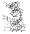
- the feet of the subject are strapped to the crank assembly, and the motor is actuated to rotate the crank, thereby moving the feet in a circular pattern similar to a bicycle pedaling motion.
- the vibrator While the legs are moving in this circular pattern, the vibrator generates vibrations which are transmitted to the crank assembly and through the assembly to the feet and legs of the subject.
- the bones of the legs are vibrated in a variety of positions to ensure that all surfaces of the bones are adequately vibrated.
- the therapeutic device of the present invention includes a base 10, a frame 12 mounted on the base, a crank assembly 14 supported by the frame, a drive motor assembly 16 and a vibrator 18.
- the base 10 includes a base plate 20 which is supported at an angle to the horizontal by struts 22 (one of which is shown). Struts 22 elevate an upper end of the base plate 20 from a foundation plate 24. Although not shown, it is within the scope of the invention to provide a base plate 20 which can be adjusted relative to the foundation plate 24 to provide a variety of angles of inclination to the horizontal to suit a particular human subject.
- the vibrator 18 preferably is a standard electromagnetic-coupled vibrator that requires an input on the order of about 12 volts to operate.
- An example of such a vibrator is the Model C31-1 vibrator manufactured by MB Manufacturing Co., Inc. of New Haven, Connecticut.
- the vibrator 18 is mounted on the base plate 20 by brackets 26, 28, which are attached to the base plate by machine screws 30.
- the frame 12 includes a pair of tubes 32, 34 which are attached to the brackets 26, 28, preferably by welding, and extend upwardly from the plane of the base plate 20.
- a pair of rods 36, 38 are shaped to telescope within the tubes 32, 34, respectively, and are attached to the underside of a support plate 40.
- the crank assembly 14 is similar in construction to the crank assembly of a conventional bicycle, and includes a bearing housing 42 which is welded to an upper surface of the support plate 40, and a crank 41, rotatably attached to the housing and including crank arms 44, 46 extending outwardly from the bearing housing, and pedals 48, 50 rotatably attached to the ends of the crank arms 44, 46, respectively.
- the pedals 48, 50 have straps 52, 54, which preferably are adjustable and include closures of the hook-and-loop type, to secure the feet 56, 58 of the legs 60, 62 of a human subject 64 to the pedals.
- the crank assembly 14 includes a driven sprocket 66 which engages an endless sprocket chain 68 that is attached to the motor assembly 16.
- Bracket 28 includes an upper arm 70 that supports a variable speed electric motor 72 comprising the motor assembly 16.
- the output shaft 74 of the motor 72 is attached to a drive sprocket 76 which engages the sprocket chain 68. Rotational movement of the drive sprocket 76 is transmitted by the sprocket chain 68 to the driven sprocket 66 to rotate the crank arms 44, 46 and pedals 48, 50 in a circular path.
- the output shaft 78 of the vibrator 18 is connected by a rigid rod 80 to the support plate 40.
- the rod 80 is screwed to the plate 40 by nuts 81 which are threaded on an upper end of the rod above and below the plate. Vibration of the output shaft 78 is thereby transmitted through the rod 80 to the support plate 40 and to the crank assembly 14.
- An accelerometer 82 is mounted on a strap 84 that is adapted to be fastened on the leg 60 of the subject 64.
- the strap 84 preferably includes a hook-and-loop type fastener so that it may be attached and removed easily from the leg 60. It is also preferable to attach the accelerometer 82 to the leg 60 near or over a bony protrusion such as the ankle bone so there is a minimum amount of skin between the accelerometer and the bone.
- the accelerometer 82 is connected to a control 86 by a wire 88, and the control is connected to the vibrator 18 by wire 90.
- the amplitude felt by the bones may be less than the magnitude of the vibrations measured at, for example, the crank 41. Furthermore, the amplitude felt will vary with the change in angular relation between the legs 60, 62 and the crank 41 as the crank is pedaled. By mounting the accelerometer 82 on the leg 60, the amplitude of the vibrations actually felt by the bones at all times is measured.
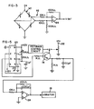
- the accelerometer 82 is of a type well-known in the art and is shown schematically in Fig. 3.
- An appropriate accelerometer is the Model 7264-2000 manufactured by Endevco Corp. of San Juan Capistrano, California.
- the accelerometer circuit includes a bridge circuit, generally designated 92, which is connected to an operational amplifier 94 to produce a voltage that varies with the amount of acceleration applied to the accelerometer.
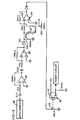
- the output of the accelerometer 82 is conducted to the control 86 through wire 88 to a vibrator feedback control circuit shown in Fig. 4.
- the accelerometer output is amplified by operational amplifiers 96, 98 and halfwave rectified by diode 100 in combination with resistor 102 and capacitor 104.
- the signal passes through an inverting buffer 106 which consists of an operational amplifier 108 and an offset voltage input 110.
- the offset voltage input 110 is adjusted so that at zero acceleration, in which there is no signal from accelerometer 82, a predetermined maximum voltage is generated by the buffer 106, and at a maximum acceleration, zero voltage passes through the inverting buffer.
- the signal is then passed through a second buffer 112 which includes a transistor 114 and a variable resistor 116, the combination acting as an impedance shifter.
- the output of the vibrator feedback control circuit is connected to the collector of a transistor 118 in a vibrator power circuit shown in Fig. 5.
- the vibrator power circuit includes a timer 120 which generates a square wave at a predetermined frequency.
- a preferred frequency is between 10 and 40 hz. Frequencies much lower than 10 hz can create a resonant vibration in the knee, which has a natural frequency of about 6 hz, that would seriously damage the bones of the knee. Vibrations having a frequency higher than 40 hz have been found to cause pathological damage to the knee.
- the square wave generated by timer 120 enters the base of the transistor 118.
- An alternate power source for the collector of transistor 118 is a 12 volt source 122 which can be varied to provide a constant voltage input.
- the square wave is then shaped to form a sine wave by a wave shaping component which includes an operational amplifier 124 connected as an integrator. The output of amplifier 124 is connected directly to the vibrator 18 by wire 90 (Fig. 2).
- the subject 64 is seated in a chair 126 of suitable height and the feet 56, 58 of the subject are strapped to the pedals 48, 50 of the crank assembly 14.
- the accelerometer 82 is strapped to the ankle of the leg 60 of the subject 64 at an appropriate location near a bone.
- the control 86 is actuated to power the vibrator 18 which transmits driving vibrations through the frame 12 and crank assembly 14 to the legs 60, 62 of the subject 64.
- the amplitude of the vibrations actually felt by the bones of the subject 64 is measured by the accelerometer 82, and a signal is generated which is used as an input in the feedback control circuit of Fig. 4.
- the output voltage at the buffer 112 is adjusted by adjusting the potentiometer 116 and/or voltage offset 110 to provide a predetermined voltage value for zero acceleration and a zero voltage output for a maximum desired acceleration. It has been found that a maximum vibration amplitude of between 10g and 50g, felt by the bones, is preferable.
- the motor 16 is actuated to rotate the crank assembly 14, thereby causing the legs 60, 62 of the subject 64 to travel in a circular path simulating the riding of a bicycle. Since the angles at which the vibrations are transmitted to the legs vary as the legs move in the circular path, the amplitude of the driving vibration must constantly change to maintain the amplitude of the vibrations felt by the bones within the aforementioned range.
- the voltage generated by the feedback circuit drops to zero thereby decreasing the amplitude of the signal from the controller circuit of Fig. 4 to the vibrator 18, although the frequency of the square wave generated by the timer 120 remains constant. This acts to reduce the amplitude of the driving vibration transmitted by the vibrator to the frame 12 and crank assembly 14 and to the legs 60, 62.
- the voltage generated by the feedback control circuit shown in Fig. 4 increases to a maximum value, effecting an increase in the amplitude of the -12- current driving the vibrator 18.
- the amplitude of the driving vibrations transmitted to the legs 60, 62 of the subject 64 remain substantially constant as the legs are moved in circular paths by the crank assembly 14, even though the angles at which the vibrations are transmitted from the crank assembly to the legs change constantly.
- Vibrations of the appropriate amplitude and frequency are, therefore, transmitted to the legs 60, 62 of the subject 64 throughout a range of motion so that all of the bone surfaces of the legs are properly vibrated, and the reversal of osteoporosis is effected in all of the bones of the legs.
- FIGs. 3, 4 and 5 depict a single circuit for providing a feedback from the legs of the subject to control the amplitude of the driving vibrations generated by the vibrator, it should be understood that other equivalent circuits may be employed by those having skill in the art without departing from the scope of the invention. Similarly, the components of the circuits depicted in Figs. 3, 4 and 5 may be changed without changing the function and operation of the circuits. Examples of typical components used in these circuits are set forth in the following table:
Landscapes
- Health & Medical Sciences (AREA)
- Epidemiology (AREA)
- Pain & Pain Management (AREA)
- Physical Education & Sports Medicine (AREA)
- Rehabilitation Therapy (AREA)
- Life Sciences & Earth Sciences (AREA)
- Animal Behavior & Ethology (AREA)
- General Health & Medical Sciences (AREA)
- Public Health (AREA)
- Veterinary Medicine (AREA)
- Percussion Or Vibration Massage (AREA)
- Rehabilitation Tools (AREA)
Applications Claiming Priority (2)
| Application Number | Priority Date | Filing Date | Title |
|---|---|---|---|
| US06/561,769 US4570927A (en) | 1983-12-15 | 1983-12-15 | Therapeutic device |
| US561769 | 2000-04-29 |
Publications (2)
| Publication Number | Publication Date |
|---|---|
| EP0145502A2 true EP0145502A2 (de) | 1985-06-19 |
| EP0145502A3 EP0145502A3 (de) | 1986-06-11 |
Family
ID=24243383
Family Applications (1)
| Application Number | Title | Priority Date | Filing Date |
|---|---|---|---|
| EP84308743A Withdrawn EP0145502A3 (de) | 1983-12-15 | 1984-12-14 | Therapeutisches Gerät |
Country Status (3)
| Country | Link |
|---|---|
| US (1) | US4570927A (de) |
| EP (1) | EP0145502A3 (de) |
| JP (1) | JPS60150749A (de) |
Cited By (6)
| Publication number | Priority date | Publication date | Assignee | Title |
|---|---|---|---|---|
| DE3623386A1 (de) * | 1986-07-11 | 1988-01-14 | Eberhard Pell | Geraet zur durchfuehrung therapeutischer bewegungsuebungen |
| WO2000027335A1 (en) * | 1998-11-05 | 2000-05-18 | The Royal Alexandra Hospital For Children | Resonant frequency stimulator and recorder |
| AU764997B2 (en) * | 1998-11-05 | 2003-09-04 | Royal Alexandra Hospital For Children, The | Resonant frequency stimulator and recorder |
| CN105434143A (zh) * | 2015-12-22 | 2016-03-30 | 天津市唐邦科技有限公司 | 多媒体下肢康复器 |
| CN112915385A (zh) * | 2021-04-02 | 2021-06-08 | 上海理工大学 | 含有电刺激功能的上肢康复治疗训练的便携式装置 |
| US12076276B2 (en) | 2019-07-19 | 2024-09-03 | Keranova | Cutting device with optical coupler including a polarisation corrector |
Families Citing this family (59)
| Publication number | Priority date | Publication date | Assignee | Title |
|---|---|---|---|---|
| US4765315A (en) * | 1984-11-29 | 1988-08-23 | Biodex Corporation | Particle brake clutch muscle exercise and rehabilitation apparatus |
| US4809696A (en) * | 1987-09-21 | 1989-03-07 | Hillcrest Medical Center | Functional electrical stimulation synchronizer switch |
| US4947836A (en) * | 1987-09-21 | 1990-08-14 | Hillcrest Medical Center | Exerciser with muscle stimulation |
| US7789841B2 (en) | 1997-02-06 | 2010-09-07 | Exogen, Inc. | Method and apparatus for connective tissue treatment |
| US5904659A (en) | 1997-02-14 | 1999-05-18 | Exogen, Inc. | Ultrasonic treatment for wounds |
| DE19716942A1 (de) * | 1997-04-23 | 1998-10-29 | Andreas Hasler | Therapie- und Trainingsgerät |
| WO1999056829A1 (en) * | 1998-05-06 | 1999-11-11 | Exogen, Inc. | Ultrasound bandages |
| US6077201A (en) * | 1998-06-12 | 2000-06-20 | Cheng; Chau-Yang | Exercise bicycle |
| WO2000071207A1 (en) | 1999-05-21 | 2000-11-30 | Exogen, Inc. | Apparatus and method for ultrasonically and electromagnetically treating tissue |
| WO2000076406A1 (en) | 1999-06-14 | 2000-12-21 | Exogen, Inc. | Method and kit for cavitation-induced tissue healing with low intensity ultrasound |
| CA2426903C (en) * | 2000-10-25 | 2011-12-06 | Exogen, Inc. | Transducer mounting assembly |
| US7429248B1 (en) | 2001-08-09 | 2008-09-30 | Exogen, Inc. | Method and apparatus for controlling acoustic modes in tissue healing applications |
| US6878122B2 (en) * | 2002-01-29 | 2005-04-12 | Oregon Health & Science University | Method and device for rehabilitation of motor dysfunction |
| US7563234B2 (en) * | 2002-01-29 | 2009-07-21 | Oregon Health & Science University | Electromyographic (EMG) feedback during AMES treatment of individuals with severe neuromuscular deficits |
| US7708706B2 (en) * | 2002-05-31 | 2010-05-04 | The Table Project, Llc | Impact table with rotatable lift disk and shock absorber |
| US20080214971A1 (en) * | 2002-10-07 | 2008-09-04 | Talish Roger J | Excercise device utilizing loading apparatus |
| US7166067B2 (en) | 2002-10-07 | 2007-01-23 | Juvent, Inc. | Exercise equipment utilizing mechanical vibrational apparatus |
| US7985191B2 (en) * | 2002-11-08 | 2011-07-26 | American Medical Innovations, L.L.C. | Apparatus and methods for therapeutically treating damaged tissues, bone fractures, osteopenia, or osteoporosis |
| US6884227B2 (en) * | 2002-11-08 | 2005-04-26 | Juvent, Inc. | Apparatuses and methods for therapeutically treating damaged tissues, bone fractures, osteopenia, or osteoporosis |
| DE10313524B3 (de) * | 2003-03-26 | 2004-09-02 | Sport-Thieme Gmbh | Trainingsgerät zur Körperertüchtigung |
| FR2855965A1 (fr) * | 2003-06-10 | 2004-12-17 | Pierre Dupuy | Stimulateur vasculaire |
| AU2005205820B2 (en) * | 2004-09-04 | 2011-04-14 | Smith & Nephew Plc | Ultrasound device and method of use |
| DE102004063495B3 (de) * | 2004-12-30 | 2006-04-27 | Quarz, Dieter, Dipl.-Ing. | Vibrationsradergometer |
| TWM278424U (en) * | 2005-01-19 | 2005-10-21 | Jeng-Neng Fan | Improvement of exercise treadmill |
| US8603017B2 (en) * | 2005-03-07 | 2013-12-10 | American Medical Innovations, L.L.C. | Vibrational therapy assembly for treating and preventing the onset of deep venous thrombosis |
| US20070043310A1 (en) * | 2005-03-07 | 2007-02-22 | Juvent Inc. | Method and apparatus for monitoring patient compliance during dynamic motion therapy |
| EP1874257A1 (de) * | 2005-03-07 | 2008-01-09 | Juvent, Inc. | Ergänzende stützstrukturen zur aufnahme einer vorrichtung für die nichtinvasive dynamische bewegungstherapie |
| US20070021693A1 (en) * | 2005-03-07 | 2007-01-25 | Titi Trandafir | Dynamic motion therapy apparatus having a treatment feedback indicator |
| US20070055185A1 (en) * | 2005-03-07 | 2007-03-08 | Juvent Inc. | Dynamic motion therapy apparatus having a treatment feedback indicator |
| JP2008534076A (ja) * | 2005-03-24 | 2008-08-28 | ジュヴェント インコーポレイテッド | 動的運動治療中の機械的振動エネルギの伝達率をモニタして制御するための機器及び方法 |
| US20080139979A1 (en) * | 2005-07-18 | 2008-06-12 | Juvent, Inc. | Vibrational therapy assembly adapted for removably mounting to a bed |
| WO2007015749A1 (en) * | 2005-07-27 | 2007-02-08 | Juvent Inc. | Method for monitoring patient compliance during dynamic motion therapy |
| US20070054778A1 (en) * | 2005-08-29 | 2007-03-08 | Blanarovich Adrian M | Apparatus and system for measuring and communicating physical activity data |
| JP4234719B2 (ja) * | 2006-02-09 | 2009-03-04 | 株式会社コナミスポーツ&ライフ | トレーニング装置 |
| US20080009776A1 (en) * | 2006-03-24 | 2008-01-10 | Juvent Inc. | Apparatus and method for monitoring and controlling the transmissibility of mechanical vibration energy during dynamic motion therapy |
| JP4150406B2 (ja) * | 2006-04-27 | 2008-09-17 | 株式会社コナミスポーツ&ライフ | トレーニング装置 |
| US8795210B2 (en) * | 2006-07-11 | 2014-08-05 | American Medical Innovations, L.L.C. | System and method for a low profile vibrating plate |
| US7390287B2 (en) * | 2006-11-09 | 2008-06-24 | Strength Master Fitness Tech Co., Ltd. | Shaking exerciser |
| US20080200847A1 (en) * | 2007-02-21 | 2008-08-21 | Joseph Bernstein | Therapeutic Device and Method for Treating and Preventing Spinal Osteoporosis |
| US20090221407A1 (en) * | 2007-09-04 | 2009-09-03 | Frauke Hauk | Biomechanical stimulation training method and apparatus |
| US20090118098A1 (en) * | 2007-11-05 | 2009-05-07 | Don-Lon Yeh | Vibration device for muscle training |
| US8123660B2 (en) * | 2007-12-28 | 2012-02-28 | Immersion Corporation | Method and apparatus for providing communications with haptic cues |
| WO2010005286A1 (en) * | 2008-06-16 | 2010-01-14 | Power Plate International Ltd. | Training system comprising a cycling device |
| DE102008028816A1 (de) * | 2008-06-19 | 2010-03-25 | Dbp Holding Gmbh | Trainingsgerät |
| IT1391359B1 (it) * | 2008-10-08 | 2011-12-13 | Technogym Spa | Dispositivo per macchina ginnica. |
| DE102009052533A1 (de) * | 2009-11-11 | 2011-05-12 | Atilla Dogan | Trainingsgerät und Verfahren zum Bewegen einer Muskulatur eines Lebewesens und Nachrüstsatz für ein Trainingsgerät |
| US7901331B1 (en) * | 2009-12-04 | 2011-03-08 | Henry William Stoll | Multi-bar linkage exercise device |
| US10206802B2 (en) * | 2011-03-07 | 2019-02-19 | Theranova, Llc | Wearable apparatus for the treatment or prevention of osteopenia and osteoporosis, stimulating bone growth, preserving or improving bone mineral density, and inhibiting adipogenesis |
| WO2014099527A1 (en) | 2012-12-17 | 2014-06-26 | Theranova, Llc | Wearable apparatus for the treatment or prevention of osteopenia and osteoporosis, stimulating bone growth, preserving or improving bone mineral density, and inhibiting adipogenesis |
| US8696533B2 (en) * | 2011-06-28 | 2014-04-15 | Preventative Medical Health Care Co., Ltd | Rehabilitation exercising equipment that can extend a user's waist, arms and legs |
| RU2672482C1 (ru) * | 2015-09-16 | 2018-11-15 | Владимир Николаевич Гладченко | Способ стимуляции произвольного сокращения мышц и устройство его реализации |
| EP3459501B8 (de) | 2017-09-22 | 2021-01-20 | Stryker European Operations Holdings LLC | Talarknöchelimplantat |
| EP3501432A1 (de) | 2017-12-20 | 2019-06-26 | Stryker European Holdings I, LLC | Gelenkinstrumentierung |
| KR20220090533A (ko) * | 2019-10-22 | 2022-06-29 | 본 헬스 테크놀로지스, 인크. | 골감소증 및 골다공증의 치료 또는 예방, 골 성장 자극, 골 무기질 밀도의 보존 또는 개선, 지방 생성 억제를 위한 장치 |
| NL2026994B1 (en) | 2020-11-26 | 2022-07-04 | Bricks And Bones Holding B V | Exercise device, distortion device, crank, method of operating an exercise device, and use of an exercise device. |
| WO2022189252A1 (de) | 2021-03-12 | 2022-09-15 | Brainaix Swiss Ag | Kompensationsvorrichtung für ein ergometer mit vibrationseinheit sowie deren verwendung in einem vibrationsergometer für die unteren und oberen extremitäten |
| WO2022189254A1 (de) | 2021-03-12 | 2022-09-15 | Brainaix Swiss Ag | Lagerung für ein ergometer mit vibrationseinheit sowie deren verwendung in einem vibrationsergometer für die unteren und oberen extremitäten |
| CN116981503A (zh) | 2021-03-12 | 2023-10-31 | 瑞士人脑智能操作股份有限公司 | 振动单元及其在上下肢振动测力计中的应用 |
| CN113230086B (zh) * | 2021-04-21 | 2022-02-22 | 广州中医药大学(广州中医药研究院) | 一种防骨质疏松的锻炼装置 |
Family Cites Families (10)
| Publication number | Priority date | Publication date | Assignee | Title |
|---|---|---|---|---|
| US2273088A (en) * | 1940-01-03 | 1942-02-17 | Byers George | Massaging table |
| GB851234A (en) * | 1957-10-25 | 1960-10-12 | Stanley Farrow | A personal exercising machine |
| US3717857A (en) * | 1970-11-27 | 1973-02-20 | Athletic Swing Measurement | Athletic swing measurement system |
| US3713438A (en) * | 1971-05-06 | 1973-01-30 | M Knutsen | Therapeutic exercising apparatus |
| US3693614A (en) * | 1971-05-28 | 1972-09-26 | Kenneth A Schon | Exercise apparatus and method for paralytic patients |
| SU584842A1 (ru) * | 1976-07-12 | 1977-12-25 | Государственный Центральный Ордена Ленина Институт Физической Культуры | Способ исследовани стопы |
| US4370602A (en) * | 1977-05-25 | 1983-01-25 | Jones Jr Johnny O | Waterbed vibrator |
| US4177796A (en) * | 1977-08-22 | 1979-12-11 | Franco Vila Jose J | Magnetic thermal vibrational device for the treatment of arthritis and the like |
| US4258706A (en) * | 1978-11-17 | 1981-03-31 | Shank Donald C | Muscle-relaxing reclining chair |
| US4480830A (en) * | 1982-09-14 | 1984-11-06 | Wright State University | Method and apparatus for exercising |
-
1983
- 1983-12-15 US US06/561,769 patent/US4570927A/en not_active Expired - Fee Related
-
1984
- 1984-12-14 EP EP84308743A patent/EP0145502A3/de not_active Withdrawn
- 1984-12-15 JP JP59265165A patent/JPS60150749A/ja active Pending
Cited By (6)
| Publication number | Priority date | Publication date | Assignee | Title |
|---|---|---|---|---|
| DE3623386A1 (de) * | 1986-07-11 | 1988-01-14 | Eberhard Pell | Geraet zur durchfuehrung therapeutischer bewegungsuebungen |
| WO2000027335A1 (en) * | 1998-11-05 | 2000-05-18 | The Royal Alexandra Hospital For Children | Resonant frequency stimulator and recorder |
| AU764997B2 (en) * | 1998-11-05 | 2003-09-04 | Royal Alexandra Hospital For Children, The | Resonant frequency stimulator and recorder |
| CN105434143A (zh) * | 2015-12-22 | 2016-03-30 | 天津市唐邦科技有限公司 | 多媒体下肢康复器 |
| US12076276B2 (en) | 2019-07-19 | 2024-09-03 | Keranova | Cutting device with optical coupler including a polarisation corrector |
| CN112915385A (zh) * | 2021-04-02 | 2021-06-08 | 上海理工大学 | 含有电刺激功能的上肢康复治疗训练的便携式装置 |
Also Published As
| Publication number | Publication date |
|---|---|
| JPS60150749A (ja) | 1985-08-08 |
| US4570927A (en) | 1986-02-18 |
| EP0145502A3 (de) | 1986-06-11 |
Similar Documents
| Publication | Publication Date | Title |
|---|---|---|
| US4570927A (en) | Therapeutic device | |
| US6923773B2 (en) | Device for vibratory stimulation on the human body | |
| US4173217A (en) | Massage apparatus | |
| US6217491B1 (en) | Device for stimulating muscles | |
| JP5042845B2 (ja) | トレーニング器具 | |
| US5297540A (en) | Continuous passive motion orthosis device for a toe | |
| JP4153996B2 (ja) | 運動器官の筋肉を刺激する装置 | |
| US20040092848A1 (en) | Apparatus and methods for therapeutically treating damaged tissues, bone fractures, osteopenia, or osteoporosis | |
| US20060217640A1 (en) | Apparatus and method for monitoring and controlling the transmissibility of mechanical vibration energy during dynamic motion therapy | |
| US20080009776A1 (en) | Apparatus and method for monitoring and controlling the transmissibility of mechanical vibration energy during dynamic motion therapy | |
| JPH049540B2 (de) | ||
| US4967736A (en) | Exercise machine for dorsal and plantar flexion | |
| US3693614A (en) | Exercise apparatus and method for paralytic patients | |
| US6319213B1 (en) | Device for passive-motion treatment of the human body | |
| EA013135B1 (ru) | Тренажер с вибропоглощающей опорой | |
| JPS63135171A (ja) | 振動治療装置 | |
| US7207954B2 (en) | Apparatus and methods for therapeutically treating damaged tissues, bone fractures, osteopenia, or osteoporosis | |
| US20070260161A1 (en) | Apparatus and methods for therapeutically treating damaged tissues, bone fractures, osteopenia, or osteoporosis | |
| GB2330769A (en) | Electrovibrator device for babies cots | |
| MX2007003231A (es) | Aparato para la estimacion selectiva de determinadas partes corporales. | |
| JP4153997B2 (ja) | 運動器官の筋肉を刺激する装置 | |
| CN87107748A (zh) | 振动治疗装置 | |
| KR101411628B1 (ko) | 3축 인체 진동기 | |
| KR200319071Y1 (ko) | 신체의 요동운동장치 | |
| RU2077266C1 (ru) | Стенд для вибродиагностики ахиллова сухожилия |
Legal Events
| Date | Code | Title | Description |
|---|---|---|---|
| PUAI | Public reference made under article 153(3) epc to a published international application that has entered the european phase |
Free format text: ORIGINAL CODE: 0009012 |
|
| AK | Designated contracting states |
Designated state(s): CH DE FR GB IT LI NL SE |
|
| PUAL | Search report despatched |
Free format text: ORIGINAL CODE: 0009013 |
|
| AK | Designated contracting states |
Kind code of ref document: A3 Designated state(s): CH DE FR GB IT LI NL SE |
|
| STAA | Information on the status of an ep patent application or granted ep patent |
Free format text: STATUS: THE APPLICATION IS DEEMED TO BE WITHDRAWN |
|
| 18D | Application deemed to be withdrawn |
Effective date: 19861212 |
|
| RIN1 | Information on inventor provided before grant (corrected) |
Inventor name: PHILLIPS, CHANDLER A. Inventor name: PETROFSKY, JERROLD S. Inventor name: HEATON III, HARRY H. |