EP0145645A2 - Dispositif tendeur, en particulier pour chaînes ou sangles - Google Patents
Dispositif tendeur, en particulier pour chaînes ou sangles Download PDFInfo
- Publication number
- EP0145645A2 EP0145645A2 EP84730129A EP84730129A EP0145645A2 EP 0145645 A2 EP0145645 A2 EP 0145645A2 EP 84730129 A EP84730129 A EP 84730129A EP 84730129 A EP84730129 A EP 84730129A EP 0145645 A2 EP0145645 A2 EP 0145645A2
- Authority
- EP
- European Patent Office
- Prior art keywords
- tensioning
- ratchet wheel
- locking
- clamping device
- drive element
- Prior art date
- Legal status (The legal status is an assumption and is not a legal conclusion. Google has not performed a legal analysis and makes no representation as to the accuracy of the status listed.)
- Granted
Links
Images
Classifications
-
- F—MECHANICAL ENGINEERING; LIGHTING; HEATING; WEAPONS; BLASTING
- F16—ENGINEERING ELEMENTS AND UNITS; GENERAL MEASURES FOR PRODUCING AND MAINTAINING EFFECTIVE FUNCTIONING OF MACHINES OR INSTALLATIONS; THERMAL INSULATION IN GENERAL
- F16G—BELTS, CABLES, OR ROPES, PREDOMINANTLY USED FOR DRIVING PURPOSES; CHAINS; FITTINGS PREDOMINANTLY USED THEREFOR
- F16G11/00—Means for fastening cables or ropes to one another or to other objects; Caps or sleeves for fixing on cables or ropes
- F16G11/12—Connections or attachments, e.g. turnbuckles, adapted for straining of cables, ropes, or wire
-
- A—HUMAN NECESSITIES
- A44—HABERDASHERY; JEWELLERY
- A44B—BUTTONS, PINS, BUCKLES, SLIDE FASTENERS, OR THE LIKE
- A44B11/00—Buckles; Similar fasteners for interconnecting straps or the like, e.g. for safety belts
- A44B11/02—Buckles; Similar fasteners for interconnecting straps or the like, e.g. for safety belts frictionally engaging surface of straps
- A44B11/06—Buckles; Similar fasteners for interconnecting straps or the like, e.g. for safety belts frictionally engaging surface of straps with clamping devices
- A44B11/12—Buckles; Similar fasteners for interconnecting straps or the like, e.g. for safety belts frictionally engaging surface of straps with clamping devices turnable clamp
- A44B11/125—Buckles; Similar fasteners for interconnecting straps or the like, e.g. for safety belts frictionally engaging surface of straps with clamping devices turnable clamp with strap tightening means
-
- Y—GENERAL TAGGING OF NEW TECHNOLOGICAL DEVELOPMENTS; GENERAL TAGGING OF CROSS-SECTIONAL TECHNOLOGIES SPANNING OVER SEVERAL SECTIONS OF THE IPC; TECHNICAL SUBJECTS COVERED BY FORMER USPC CROSS-REFERENCE ART COLLECTIONS [XRACs] AND DIGESTS
- Y10—TECHNICAL SUBJECTS COVERED BY FORMER USPC
- Y10S—TECHNICAL SUBJECTS COVERED BY FORMER USPC CROSS-REFERENCE ART COLLECTIONS [XRACs] AND DIGESTS
- Y10S24/00—Buckles, buttons, clasps
- Y10S24/909—Winders for flexible material
-
- Y—GENERAL TAGGING OF NEW TECHNOLOGICAL DEVELOPMENTS; GENERAL TAGGING OF CROSS-SECTIONAL TECHNOLOGIES SPANNING OVER SEVERAL SECTIONS OF THE IPC; TECHNICAL SUBJECTS COVERED BY FORMER USPC CROSS-REFERENCE ART COLLECTIONS [XRACs] AND DIGESTS
- Y10—TECHNICAL SUBJECTS COVERED BY FORMER USPC
- Y10T—TECHNICAL SUBJECTS COVERED BY FORMER US CLASSIFICATION
- Y10T24/00—Buckles, buttons, clasps, etc.
- Y10T24/21—Strap tighteners
-
- Y—GENERAL TAGGING OF NEW TECHNOLOGICAL DEVELOPMENTS; GENERAL TAGGING OF CROSS-SECTIONAL TECHNOLOGIES SPANNING OVER SEVERAL SECTIONS OF THE IPC; TECHNICAL SUBJECTS COVERED BY FORMER USPC CROSS-REFERENCE ART COLLECTIONS [XRACs] AND DIGESTS
- Y10—TECHNICAL SUBJECTS COVERED BY FORMER USPC
- Y10T—TECHNICAL SUBJECTS COVERED BY FORMER US CLASSIFICATION
- Y10T24/00—Buckles, buttons, clasps, etc.
- Y10T24/21—Strap tighteners
- Y10T24/2175—Cargo tie down
Definitions
- the invention relates to a tensioning device for tensioning strands, in particular chains or belts, with a rotatable drive element serving to wind up the tensioning strand, at least one ratchet wheel having non-rotatably connected directionally oriented ratchet teeth, and to a pivoting lever serving to initiate the rotary movement into the drive element, on which one with the ratchet cooperating drive pawl is slidably mounted against the action of a spring and is provided with at least one control cam for transferring a locking mechanism assigned to the ratchet wheel into an ineffective position, the teeth of the ratchet wheel being shaped such that they move in one direction when the pivoting lever is moved are held by the locking mechanism, while they are carried along by the pawl when the pivot lever is moved in the opposite direction.
- a tensioning device of the type under consideration is known in which the free end of the tensioning lever has to be moved away from the tensioning device for tensioning the tensioning strand.
- Such an embodiment of the tensioning device is unsatisfactory from an ergonomic point of view. This applies in particular in cases where the tensioning device for lashing down loads on vehicles is used.
- the invention has for its object to redesign a tensioning device of the type under consideration such that it enables more convenient handling by allowing its user to use his body weight when operating the tensioning lever. In this way, high, short prestressing tension peaks can be realized, which enable the introduction of high prestressing forces into the tension strand.
- the object on which the invention is based is achieved in that the ratchet teeth of the ratchet wheel are shaped such that the tooth back of the ratchet tooth which is in engagement with the ratchet mechanism in the locked position of the ratchet wheel faces away from the free end of the pivot lever.
- the tensioning device according to the invention has the advantage that the application of the high pre-tensioning forces, particularly desired when lashing down loads, is considerably facilitated in a surprisingly simple manner, namely by reversing the direction of movement of the tensioning lever compared to conventional tensioning devices of the type under consideration.
- an embodiment of the tensioning device according to claim 5 proves to be advantageous.
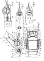
- 1 and 2 are side walls of a tensioning device, between which a drive element 3 for a tensioning strand 4 is rotatably mounted.
- the tension cord 4 is formed in the case shown by a belt.
- two ratchet wheels 5 are rotatably connected, which are provided with a plurality of load-oriented locking teeth 6.
- a pivot lever 7 is pivotally mounted on the drive element about the axis of rotation thereof.
- a drive pawl 9 is displaceably guided against the action of a spring 8, which, when the swivel lever rotates in the clockwise direction Takes ratchet 5.
- the locking element 10 and 11 are two slide-shaped locking elements forming a locking mechanism.
- the locking element 10 is supported by a spring 12 and the locking element 11 by two springs 13 against a yoke 14.
- the locking teeth 6 of the two ratchet wheels 5 arranged on both sides of the side walls 1 and 2 are shaped such that the tooth back 15 of the ratchet tooth 6, which is in engagement with the locking mechanism 10, 11 in the locked position of the ratchet wheels 5 not shown free end of the pivot lever 7 is facing away.
- a guide member 17 is arranged for the tension cord 4 connected to the drive element 3.
- the guide member 17, like the drive element 3, is held in the side walls 1 and 2 of the tensioning device. For this purpose, this is provided with fork-like extensions 18 and 19.
- the management body 17 exists preferably from a sleeve rotatably mounted on a pin 20.
- the guide member is positioned such that the forces introduced into the tensioning device by the tensioning string 4 and the further tensioning string 21 connected to the tensioning device become effective along a line 22 which runs essentially parallel to a support surface 23 with which the Tensioning device can be placed against a load if it is used to lash the load down.
- the position of line 22 depends on the design of the second tension cord connection of the tensioning device.
Landscapes
- Engineering & Computer Science (AREA)
- General Engineering & Computer Science (AREA)
- Mechanical Engineering (AREA)
- Devices For Conveying Motion By Means Of Endless Flexible Members (AREA)
- Spinning Or Twisting Of Yarns (AREA)
- Tension Adjustment In Filamentary Materials (AREA)
- Basic Packing Technique (AREA)
- Hand Tools For Fitting Together And Separating, Or Other Hand Tools (AREA)
Priority Applications (1)
| Application Number | Priority Date | Filing Date | Title |
|---|---|---|---|
| AT84730129T ATE54998T1 (de) | 1983-12-06 | 1984-11-30 | Spannvorrichtung fuer spannstraenge, insbesondere ketten oder gurte. |
Applications Claiming Priority (2)
| Application Number | Priority Date | Filing Date | Title |
|---|---|---|---|
| DE3344486A DE3344486C1 (de) | 1983-12-06 | 1983-12-06 | Spannvorrichtung für Spannstränge, insbesondere Ketten oder Gurte |
| DE3344486 | 1983-12-06 |
Publications (3)
| Publication Number | Publication Date |
|---|---|
| EP0145645A2 true EP0145645A2 (fr) | 1985-06-19 |
| EP0145645A3 EP0145645A3 (en) | 1987-10-14 |
| EP0145645B1 EP0145645B1 (fr) | 1990-07-25 |
Family
ID=6216427
Family Applications (1)
| Application Number | Title | Priority Date | Filing Date |
|---|---|---|---|
| EP19840730129 Expired - Lifetime EP0145645B1 (fr) | 1983-12-06 | 1984-11-30 | Dispositif tendeur, en particulier pour chaînes ou sangles |
Country Status (6)
| Country | Link |
|---|---|
| US (1) | US4584742A (fr) |
| EP (1) | EP0145645B1 (fr) |
| JP (1) | JPS60155378A (fr) |
| AT (1) | ATE54998T1 (fr) |
| AU (1) | AU562330B2 (fr) |
| DE (2) | DE3344486C1 (fr) |
Families Citing this family (16)
| Publication number | Priority date | Publication date | Assignee | Title |
|---|---|---|---|---|
| DE8703372U1 (de) * | 1987-03-06 | 1988-07-07 | Eisen- Und Drahtwerk Erlau Ag, 7080 Aalen | Gurtanschlußvorrichtung |
| US4823443A (en) * | 1987-06-18 | 1989-04-25 | Veldon Waters | Strap tie down device and method for its use |
| CA2040850C (fr) * | 1990-05-03 | 1995-09-19 | Hans-Werner Kamper | Ensemble tendeur servant a serrer et a desserrer une bande de tension |
| DE9016471U1 (de) * | 1990-12-04 | 1991-04-04 | Dolezych, Udo, Dipl.-Kaufm., 58313 Herdecke | Spannvorrichtung |
| US5205020A (en) * | 1991-03-08 | 1993-04-27 | Spanset Inter Ag | Tensioning apparatus for a lashing strap |
| US5218743A (en) * | 1991-07-22 | 1993-06-15 | John Miller | Connecting device |
| SE500013C2 (sv) * | 1992-03-16 | 1994-03-21 | Sven Erik Soederstroem | Banduppsamlare |
| USD364364S (en) | 1994-06-24 | 1995-11-21 | Takigen Manufacturing Co. Ltd. | Buckle for cargo straps |
| DE29506142U1 (de) * | 1995-04-08 | 1996-08-01 | Spanset Inter Ag, Oetwil Am See | Spannratsche |
| US6769155B2 (en) * | 2000-08-18 | 2004-08-03 | Mammut Tec Ag | Tensioning and relaxing element |
| EP1464537A1 (fr) * | 2003-04-04 | 2004-10-06 | Pony Ma | Dispositif de serrage de courroie |
| US7207089B2 (en) * | 2003-12-11 | 2007-04-24 | Burton Warren Hanson | Bi-directional load securing ratchet method and apparatus |
| US7503546B1 (en) * | 2006-03-01 | 2009-03-17 | Richard Seager | Light weight strap winder |
| US8191208B2 (en) * | 2008-06-06 | 2012-06-05 | Hanson Burton W | Load securing ratchet with anchor attachment system |
| USD682153S1 (en) * | 2012-09-14 | 2013-05-14 | Robert S. Dickey | Double cam buckle |
| US11414006B2 (en) * | 2020-08-18 | 2022-08-16 | Nicholas Deplaris | Locking mechanism for tie down locking device |
Family Cites Families (17)
| Publication number | Priority date | Publication date | Assignee | Title |
|---|---|---|---|---|
| DE8022576U1 (de) * | 1982-02-04 | Eisen-und Drahtwerk Erlau AG, 7080 Aalen | Ratsche zum Spannen von Gurten, Seilen u.dgl. | |
| US1206019A (en) * | 1916-02-19 | 1916-11-28 | Edward Brown Moore | Power-pulley. |
| US1375558A (en) * | 1920-09-03 | 1921-04-19 | Butner William Richardson | Ratchet-chain block |
| US2363138A (en) * | 1943-07-15 | 1944-11-21 | Schuler Engineering Company | Reversible hand-operated windlass |
| US2993680A (en) * | 1960-05-10 | 1961-07-25 | Frank L Davis | Quick adjustment, ratchet tensioned tiedown |
| US3175806A (en) * | 1963-11-04 | 1965-03-30 | Brown Line Corp | Ratchet buckle |
| GB1337679A (en) * | 1971-03-04 | 1973-11-21 | Irvin Great Britain Ltd | Ratchet tensioners |
| ZA721341B (en) * | 1971-03-04 | 1972-11-29 | Irvan Great Britain Ltd | Improvements in or relating to ratchet tensioners |
| US3749366A (en) * | 1972-05-22 | 1973-07-31 | Kinedyne Corp | Ratchet buckle |
| US3826473A (en) * | 1972-12-26 | 1974-07-30 | Trans Technology Corp | Slidable buckle assembly |
| SE408695B (sv) * | 1977-10-31 | 1979-07-02 | Goteborgs Bandveveri Ab | Anordning vid organ for atspenning och lasning av sling eller lastband |
| SE412557C (sv) * | 1978-04-28 | 1985-07-15 | Holmbergs Fab Ab Brdr | Bandstreckare |
| US4185360A (en) * | 1978-08-14 | 1980-01-29 | Ancra Corporation | Ratchet buckle for tightening and tensioning strap |
| DE3017371A1 (de) * | 1980-05-07 | 1981-11-12 | Spanset Inter AG, 4002 Basel | Spannratsche fuer zurrgurte |
| US4324022A (en) * | 1980-06-16 | 1982-04-13 | Ancra Corporation | Ratchet buckle having reinforcement strengthening means |
| GB2105805B (en) * | 1981-07-10 | 1985-07-03 | Spanset Inter Ag | Ratchet device for tightening belts surrounding loads on trailers |
| DE8229264U1 (de) * | 1982-10-19 | 1983-02-03 | Henssgen Karabinerhaken GmbH, 5603 Wülfrath | Spannvorrichtung fuer zurrgurte od. dgl. |
-
1983
- 1983-12-06 DE DE3344486A patent/DE3344486C1/de not_active Expired - Lifetime
-
1984
- 1984-11-30 AT AT84730129T patent/ATE54998T1/de active
- 1984-11-30 DE DE8484730129T patent/DE3482824D1/de not_active Expired - Lifetime
- 1984-11-30 EP EP19840730129 patent/EP0145645B1/fr not_active Expired - Lifetime
- 1984-12-03 US US06/677,165 patent/US4584742A/en not_active Expired - Lifetime
- 1984-12-05 AU AU36330/84A patent/AU562330B2/en not_active Ceased
- 1984-12-06 JP JP59258413A patent/JPS60155378A/ja active Pending
Also Published As
| Publication number | Publication date |
|---|---|
| DE3344486C1 (de) | 1990-10-04 |
| AU562330B2 (en) | 1987-06-04 |
| DE3482824D1 (de) | 1990-08-30 |
| US4584742A (en) | 1986-04-29 |
| EP0145645A3 (en) | 1987-10-14 |
| EP0145645B1 (fr) | 1990-07-25 |
| JPS60155378A (ja) | 1985-08-15 |
| ATE54998T1 (de) | 1990-08-15 |
| AU3633084A (en) | 1985-06-13 |
Similar Documents
| Publication | Publication Date | Title |
|---|---|---|
| EP0145643B1 (fr) | Dispositif de liaison d'éléments d'assemblage, de dispositifs tendeurs et/ou de contrôle avec des sangles | |
| DE3344486C1 (de) | Spannvorrichtung für Spannstränge, insbesondere Ketten oder Gurte | |
| EP0145644B1 (fr) | Dispositif tendeur, en particulier pour chaînes ou sangles | |
| DE3317359A1 (de) | Spannvorrichtung, insbesondere fuer eine skibindung | |
| CH637336A5 (de) | Gurtspanner. | |
| EP1311408A1 (fr) | Element tendeur et de relachement | |
| DE1275814B (de) | Verschluss-Schnalle fuer Sicherheitsgurte od. dgl. | |
| DE2324682A1 (de) | Verschluss fuer ein armband | |
| DE69403033T2 (de) | Werkzeug zum Spannen eines Bandelements | |
| EP0016317A1 (fr) | Attelage réglabe en hanteur pour remorque | |
| DE2346908A1 (de) | Haltevorrichtung fuer einen aufrollbaren sicherheitsgurt | |
| DE69301798T2 (de) | Schwenkbarer Tisch mit Motorwerkzeug | |
| EP1713618B1 (fr) | Dispositif d'affutage de couteau | |
| EP0389831A2 (fr) | Dispositif pour ligaturer des éléments allongés | |
| EP0130138A1 (fr) | Elément de chaîne à maillons ronds | |
| DD151432A5 (de) | Kettenfoerderer | |
| DE2704417C3 (de) | Reinigungsgerät mit auswechselbarem Bezug | |
| DE112020001328T5 (de) | Vorrichtung zum Tragen von Lasten | |
| DE3842402C1 (fr) | ||
| DE69615604T2 (de) | Vorrichtung zur Sicherung von Lasten auf einem KFZ | |
| EP0489376A2 (fr) | Dispositif tendeur | |
| DE3017371A1 (de) | Spannratsche fuer zurrgurte | |
| DE3401529A1 (de) | Verstellvorrichtung fuer einen sicherheitsgurt-anlenkpunkt | |
| DE3323539A1 (de) | Gelenkbeschlag fuer sitze mit verstellbarer rueckenlehne, insbesondere kraftfahrzeugsitze | |
| DE3008764A1 (de) | Betaetigungseinrichtung zum entriegeln einer verriegeln sitzanordnung in einem fahrzeug |
Legal Events
| Date | Code | Title | Description |
|---|---|---|---|
| PUAI | Public reference made under article 153(3) epc to a published international application that has entered the european phase |
Free format text: ORIGINAL CODE: 0009012 |
|
| AK | Designated contracting states |
Designated state(s): AT CH DE GB IT LI SE |
|
| RTI1 | Title (correction) | ||
| PUAL | Search report despatched |
Free format text: ORIGINAL CODE: 0009013 |
|
| AK | Designated contracting states |
Kind code of ref document: A3 Designated state(s): AT CH DE GB IT LI SE |
|
| 17P | Request for examination filed |
Effective date: 19871211 |
|
| 17Q | First examination report despatched |
Effective date: 19890130 |
|
| GRAA | (expected) grant |
Free format text: ORIGINAL CODE: 0009210 |
|
| AK | Designated contracting states |
Kind code of ref document: B1 Designated state(s): AT CH DE GB IT LI SE |
|
| REF | Corresponds to: |
Ref document number: 54998 Country of ref document: AT Date of ref document: 19900815 Kind code of ref document: T |
|
| REF | Corresponds to: |
Ref document number: 3482824 Country of ref document: DE Date of ref document: 19900830 |
|
| ITF | It: translation for a ep patent filed | ||
| GBT | Gb: translation of ep patent filed (gb section 77(6)(a)/1977) | ||
| RIN2 | Information on inventor provided after grant (corrected) |
Free format text: SPEICH, HELMUT |
|
| R20 | Corrections of a patent specification |
Effective date: 19900829 |
|
| PLBE | No opposition filed within time limit |
Free format text: ORIGINAL CODE: 0009261 |
|
| STAA | Information on the status of an ep patent application or granted ep patent |
Free format text: STATUS: NO OPPOSITION FILED WITHIN TIME LIMIT |
|
| 26N | No opposition filed | ||
| ITTA | It: last paid annual fee | ||
| EAL | Se: european patent in force in sweden |
Ref document number: 84730129.8 |
|
| PGFP | Annual fee paid to national office [announced via postgrant information from national office to epo] |
Ref country code: SE Payment date: 19971121 Year of fee payment: 14 Ref country code: AT Payment date: 19971121 Year of fee payment: 14 |
|
| PGFP | Annual fee paid to national office [announced via postgrant information from national office to epo] |
Ref country code: GB Payment date: 19981116 Year of fee payment: 15 |
|
| PGFP | Annual fee paid to national office [announced via postgrant information from national office to epo] |
Ref country code: CH Payment date: 19981126 Year of fee payment: 15 |
|
| PG25 | Lapsed in a contracting state [announced via postgrant information from national office to epo] |
Ref country code: AT Free format text: LAPSE BECAUSE OF NON-PAYMENT OF DUE FEES Effective date: 19981130 |
|
| PG25 | Lapsed in a contracting state [announced via postgrant information from national office to epo] |
Ref country code: SE Free format text: LAPSE BECAUSE OF NON-PAYMENT OF DUE FEES Effective date: 19981201 |
|
| PG25 | Lapsed in a contracting state [announced via postgrant information from national office to epo] |
Ref country code: LI Free format text: LAPSE BECAUSE OF NON-PAYMENT OF DUE FEES Effective date: 19991130 Ref country code: GB Free format text: LAPSE BECAUSE OF NON-PAYMENT OF DUE FEES Effective date: 19991130 Ref country code: CH Free format text: LAPSE BECAUSE OF NON-PAYMENT OF DUE FEES Effective date: 19991130 |
|
| PGFP | Annual fee paid to national office [announced via postgrant information from national office to epo] |
Ref country code: DE Payment date: 19991217 Year of fee payment: 16 |
|
| REG | Reference to a national code |
Ref country code: CH Ref legal event code: PL |
|
| GBPC | Gb: european patent ceased through non-payment of renewal fee |
Effective date: 19991130 |
|
| PG25 | Lapsed in a contracting state [announced via postgrant information from national office to epo] |
Ref country code: DE Free format text: LAPSE BECAUSE OF NON-PAYMENT OF DUE FEES Effective date: 20010801 |