EP0145679A2 - Mehrfach brauchbarer Baublock und mit diesem Block hergestellte Baustruktur - Google Patents
Mehrfach brauchbarer Baublock und mit diesem Block hergestellte Baustruktur Download PDFInfo
- Publication number
- EP0145679A2 EP0145679A2 EP84830321A EP84830321A EP0145679A2 EP 0145679 A2 EP0145679 A2 EP 0145679A2 EP 84830321 A EP84830321 A EP 84830321A EP 84830321 A EP84830321 A EP 84830321A EP 0145679 A2 EP0145679 A2 EP 0145679A2
- Authority
- EP
- European Patent Office
- Prior art keywords
- block
- parts
- resistant
- fact
- building structure
- Prior art date
- Legal status (The legal status is an assumption and is not a legal conclusion. Google has not performed a legal analysis and makes no representation as to the accuracy of the status listed.)
- Withdrawn
Links
Images

Classifications
-
- E—FIXED CONSTRUCTIONS
- E04—BUILDING
- E04B—GENERAL BUILDING CONSTRUCTIONS; WALLS, e.g. PARTITIONS; ROOFS; FLOORS; CEILINGS; INSULATION OR OTHER PROTECTION OF BUILDINGS
- E04B2/00—Walls, e.g. partitions, for buildings; Wall construction with regard to insulation; Connections specially adapted to walls
- E04B2/02—Walls, e.g. partitions, for buildings; Wall construction with regard to insulation; Connections specially adapted to walls built-up from layers of building elements
-
- E—FIXED CONSTRUCTIONS
- E04—BUILDING
- E04B—GENERAL BUILDING CONSTRUCTIONS; WALLS, e.g. PARTITIONS; ROOFS; FLOORS; CEILINGS; INSULATION OR OTHER PROTECTION OF BUILDINGS
- E04B2/00—Walls, e.g. partitions, for buildings; Wall construction with regard to insulation; Connections specially adapted to walls
- E04B2/02—Walls, e.g. partitions, for buildings; Wall construction with regard to insulation; Connections specially adapted to walls built-up from layers of building elements
- E04B2/14—Walls having cavities in, but not between, the elements, i.e. each cavity being enclosed by at least four sides forming part of one single element
-
- E—FIXED CONSTRUCTIONS
- E04—BUILDING
- E04B—GENERAL BUILDING CONSTRUCTIONS; WALLS, e.g. PARTITIONS; ROOFS; FLOORS; CEILINGS; INSULATION OR OTHER PROTECTION OF BUILDINGS
- E04B2/00—Walls, e.g. partitions, for buildings; Wall construction with regard to insulation; Connections specially adapted to walls
- E04B2/02—Walls, e.g. partitions, for buildings; Wall construction with regard to insulation; Connections specially adapted to walls built-up from layers of building elements
- E04B2002/0256—Special features of building elements
- E04B2002/026—Splittable building elements
Definitions
- building structures create considerable practical problems both from a formation viewpoint and as regards the connection thereof to parts that are not made of concrete. Such practical problems could be solved by placing suitably sized burnt clay elements around the concrete.
- the technical task forming the basis of the invention is to devise a block which, apart from specific uses of a conventional type, can also be utilized in various ways in a building structure, so as to overcome the above mentioned shortcomings.
- One important object within the framework of the said technical task is to devise a block able, at the choice of the user, to adopt a variety of structural configurations without any need for adaptation operations that are complex or call for the use of special equipment.
- Another, though not final, object of the invention is to devise a block that is simple and can easily be produced by industries in the field concerned.
- a flat burnt clay element comprising a first main surface and a second main surface interconnected by a plurality of side-by-side ribs that form there with channels parallel both one to the other and to the main extension direction of the said burnt clay element, two of the said plurality of ribs defining the longitudinal sides of the said element, and characterized by the fact of comprising : a resistant part defined by the said first main surface and by at least the said two ribs that form the longitudinal sides of the said element, and an auxiliary part defined by the said second main surface and by the remaining ribs, the said resistant part having cross sections greater than those of the said auxiliary part.
- Pared corners are advantageously provided in the areas of connection between the said resistant part and the said auxiliary part in order to encourage the separation one from the other of these.
- the block according to the invention is shown globally at 1.
- the block is provided with a first main surface 2 and a second main surface 3 that define the longest surfaces of the said element.
- the surfaces 2 and 3 are interconnected by a plurality of ribs subdivided into central ribs 4 and border ribs. The latter define the principal longitudinal sides 5 of the block 1..
- Running between the said ribs are channels 6 that are parallel both one to the other and to the main extension direction of the block 1.
- the block 1 is fundamentally subdivided into parts: namely a resistant part 7 and an auxiliary part 8.
- the resistant part 7 is defined by the first main surface 2 and by the longitudinal sides 5 of the block 1.
- the auxiliary part 8 is, instead, defined by the second main surface 3 and by the central ribs 4.
- the resistant part 7 has cross sections greater than and preferably double those of the said auxiliary part.
- the resistant part 7 is essentially of a "U" shape that is interrupted only by localized enlargements in, out of preference, the region of the corners.
- Another original aspect envisages that in the areas of connection between the resistant part 7 and the auxiliary part 8 the separation of one part from the other be encouraged by the concavities shown at 9 that are preferably defined by recesses fashioned at the time the block is being made.
- the block in common with burnt clay elements in general, is produced by simple extrusion.
- the block 1 can be utilized in the construction of horizontal frameworks.
- the block 1 is used complete with all the parts thereof, and the resistance offered by the part 7 enables particularly light layers 10 of concrete to be formed.
- the block 1 according to the invention can unconventionally be utilized to circumscribe pipework etcetera and for non re- utilizable structure shuttering.
- the block 1 is utilized removing there from the auxiliary block 8 and leaving there with the resistant part 7, with the typical "U" shape of this.
- the resistant parts 7 can be utilized for the circumscription not only of pipework etcetera in newly constructed buildings but also when old buildings are being restored and every time it is wished to update obsolete or deteriorated plants. In this way, the danger of breakages due to stray voltages and galvanic currents is eliminated and, above all, every one of the problems originated by the pre-existing constructional technique, in itself costly and erroneous from both a functional and a rational viewpoint, is obviated.
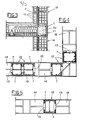
- Figure 4 shows, in a plan view, the double columns 12, and Figure 5, a single column 12.
- the said columns or elements of support are delimited by resistant parts 7 that replace the customary shuttering. Thanks to this, the columns can be formed in a fast and simple way; furthermore, it is possible to leave open parts 13 that allow the concrete to spread and join, one to the other, two columns or to seal the spaces in between a column and the non-bearing wall 14.
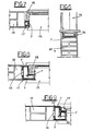
- the blocks 1 allow the construction not only of a main frame defined by girders and columns but also of an auxiliary strengthening frame defined by the pillars 17 placed preferably in a position wherein able to form the vertical support elements of the windows, and by the cross beams 16 that can define the horizontal support elements of the windows.
- Figures 7, 8 and 9 show that the formation of the said auxiliary frame, in particular the pillars 17 that define the vertical elements of the windows, does not give rise to limitations in the shape of the said pillars.
- the block 1, with the auxiliary part 8 removed, is placed in position at the same time as the non-bearing wall 14.
- the concrete 20 laid compresses and seals the said wall thereby eliminating the danger of flaws between this and the concrete part.
- the invention attains the objects proposed. Particular stress is laid on the fact that the block according to the invention makes it possible to erect not only more rational and better organized building structures, as shown in Figure 3, but also building structures with which the essential advantage is achieved of the peripheral resistance being, at will, easily increased.
- the shearing forces applied to the inside frames are eliminated and this is beneficial to the architectural requirements since the use is possible of girders and pillars of a limited size, as well as of assymmetrical mesh frames.
Landscapes
- Engineering & Computer Science (AREA)
- Architecture (AREA)
- Physics & Mathematics (AREA)
- Electromagnetism (AREA)
- Civil Engineering (AREA)
- Structural Engineering (AREA)
- Building Environments (AREA)
- Buildings Adapted To Withstand Abnormal External Influences (AREA)
Applications Claiming Priority (2)
| Application Number | Priority Date | Filing Date | Title |
|---|---|---|---|
| IT8303651A IT1208111B (it) | 1983-12-07 | 1983-12-07 | Tavellone a piu' impieghi in campo edilizio e struttura edile utilizzante il detto tavellone |
| IT365183 | 1983-12-07 |
Publications (2)
| Publication Number | Publication Date |
|---|---|
| EP0145679A2 true EP0145679A2 (de) | 1985-06-19 |
| EP0145679A3 EP0145679A3 (de) | 1985-07-03 |
Family
ID=11111120
Family Applications (1)
| Application Number | Title | Priority Date | Filing Date |
|---|---|---|---|
| EP84830321A Withdrawn EP0145679A3 (de) | 1983-12-07 | 1984-11-28 | Mehrfach brauchbarer Baublock und mit diesem Block hergestellte Baustruktur |
Country Status (2)
| Country | Link |
|---|---|
| EP (1) | EP0145679A3 (de) |
| IT (1) | IT1208111B (de) |
Cited By (1)
| Publication number | Priority date | Publication date | Assignee | Title |
|---|---|---|---|---|
| EP0675239A1 (de) * | 1994-03-30 | 1995-10-04 | Firma Hermann Uhl | Mauerstein-Bausatz. |
Family Cites Families (2)
| Publication number | Priority date | Publication date | Assignee | Title |
|---|---|---|---|---|
| FR1061400A (fr) * | 1952-08-11 | 1954-04-12 | Nouvel élément de construction | |
| FR2142915B3 (de) * | 1971-06-21 | 1973-07-13 | Laria Spa |
-
1983
- 1983-12-07 IT IT8303651A patent/IT1208111B/it active
-
1984
- 1984-11-28 EP EP84830321A patent/EP0145679A3/de not_active Withdrawn
Cited By (1)
| Publication number | Priority date | Publication date | Assignee | Title |
|---|---|---|---|---|
| EP0675239A1 (de) * | 1994-03-30 | 1995-10-04 | Firma Hermann Uhl | Mauerstein-Bausatz. |
Also Published As
| Publication number | Publication date |
|---|---|
| IT8303651A0 (it) | 1983-12-07 |
| IT1208111B (it) | 1989-06-06 |
| EP0145679A3 (de) | 1985-07-03 |
Similar Documents
| Publication | Publication Date | Title |
|---|---|---|
| CN207660136U (zh) | 一种装配式混凝土框架剪力墙键槽连接结构 | |
| WO2002066757A9 (en) | A load bearing building panel | |
| CN110424447B (zh) | 一种装配式变电站一体化基础结构及其施工方法 | |
| EP1561874A1 (de) | Verbindungsvorrichtung und Knotenpunktverbindung für Gebäude aus vorgefertigten Elementen | |
| RU165803U1 (ru) | Сборно-монолитное перекрытие каркасного здания | |
| RU80487U1 (ru) | Система сборного каркасного домостроения (скд) и узел сопряжения корытообразных ребристых плит перекрытия с сборно-монолитным ригелем, перекрытие, узел стыка сборных железобетонных колонн, узел сопряжения сборно-монолитного ригеля со сборной железобетонной колонной и корытообразной ребристой плитой перекрытия | |
| RU2184816C1 (ru) | Сборно-монолитный железобетонный каркас многоэтажного здания "казань-1000" | |
| CN220225867U (zh) | 一种免模免撑的叠合板及其连接结构 | |
| GB2407828A (en) | Prefabricated structural masonry wall panel | |
| EA010319B1 (ru) | Комбинированная конструктивная система многоэтажных зданий в обычных и сейсмических условиях | |
| CN210421398U (zh) | 一种装配式住宅体系 | |
| RU2281362C1 (ru) | СБОРНО-МОНОЛИТНЫЙ ЖЕЛЕЗОБЕТОННЫЙ КАРКАС МНОГОЭТАЖНОГО ЗДАНИЯ "КАЗАНЬ-XXIв" | |
| CN114032967A (zh) | 地下室外墙后浇带提前封闭的模板装置及模板支设方法 | |
| RU88036U1 (ru) | Унифицированный железобетонный сборно-омоноличенный колонно-стеновой каркас здания | |
| RU2634139C1 (ru) | Каркасная универсальная полносборная архитектурно-строительная система | |
| CN207974254U (zh) | 一种拉紧锚固法连接型装配式墙-板结构 | |
| CN205604516U (zh) | 一种装配式整间空心内墙板 | |
| CN206987180U (zh) | 一种建筑用新型预制混凝土板 | |
| RU172744U1 (ru) | Сборно-монолитное перекрытие каркасного здания | |
| CN224149000U (zh) | 一种可以快速安装的外墙构造柱结构及其应用的楼体 | |
| JPH07217020A (ja) | プレキャスト壁式鉄筋コンクリート造の壁接合構造 | |
| RU2130106C1 (ru) | Способы выполнения конструктивной системы полносборного здания гражданского назначения | |
| US20050093190A1 (en) | Concrete structures and construction methods | |
| CN219825611U (zh) | 一种装配式免拆型楼承板与混凝土梁的连接构造 | |
| KR20020075133A (ko) | 설비덕트를 포함하는 개량 t형 슬래브 및 이와 관련한 공법 |
Legal Events
| Date | Code | Title | Description |
|---|---|---|---|
| PUAI | Public reference made under article 153(3) epc to a published international application that has entered the european phase |
Free format text: ORIGINAL CODE: 0009012 |
|
| PUAL | Search report despatched |
Free format text: ORIGINAL CODE: 0009013 |
|
| AK | Designated contracting states |
Designated state(s): AT CH DE FR LI |
|
| AK | Designated contracting states |
Designated state(s): AT CH DE FR LI |
|
| STAA | Information on the status of an ep patent application or granted ep patent |
Free format text: STATUS: THE APPLICATION HAS BEEN WITHDRAWN |
|
| 18W | Application withdrawn |
Withdrawal date: 19851211 |