EP0145680A2 - Rohrförmige Einbauleuchte - Google Patents
Rohrförmige Einbauleuchte Download PDFInfo
- Publication number
- EP0145680A2 EP0145680A2 EP84830325A EP84830325A EP0145680A2 EP 0145680 A2 EP0145680 A2 EP 0145680A2 EP 84830325 A EP84830325 A EP 84830325A EP 84830325 A EP84830325 A EP 84830325A EP 0145680 A2 EP0145680 A2 EP 0145680A2
- Authority
- EP
- European Patent Office
- Prior art keywords
- tubular body
- lamp
- seat
- engage
- fact
- Prior art date
- Legal status (The legal status is an assumption and is not a legal conclusion. Google has not performed a legal analysis and makes no representation as to the accuracy of the status listed.)
- Withdrawn
Links
Images
Classifications
-
- F—MECHANICAL ENGINEERING; LIGHTING; HEATING; WEAPONS; BLASTING
- F21—LIGHTING
- F21V—FUNCTIONAL FEATURES OR DETAILS OF LIGHTING DEVICES OR SYSTEMS THEREOF; STRUCTURAL COMBINATIONS OF LIGHTING DEVICES WITH OTHER ARTICLES, NOT OTHERWISE PROVIDED FOR
- F21V21/00—Supporting, suspending, or attaching arrangements for lighting devices; Hand grips
- F21V21/02—Wall, ceiling, or floor bases; Fixing pendants or arms to the bases
- F21V21/04—Recessed bases
-
- F—MECHANICAL ENGINEERING; LIGHTING; HEATING; WEAPONS; BLASTING
- F21—LIGHTING
- F21S—NON-PORTABLE LIGHTING DEVICES; SYSTEMS THEREOF; VEHICLE LIGHTING DEVICES SPECIALLY ADAPTED FOR VEHICLE EXTERIORS
- F21S8/00—Lighting devices intended for fixed installation
- F21S8/02—Lighting devices intended for fixed installation of recess-mounted type, e.g. downlighters
Definitions
- the invention has the object to provide a lamp to be socketed into a seat formed in a wall or in a panelling or other, which assembly includes a tubular body able to receive the lamp-holder or lamp, and able to be received into the seat; said tubular body presents at the open end an external flange able to engage a finishing annular frame, while at the opposite side the tubular body presents a closing head.
- the closing head may engage a connection box.
- guide means may be provided for engaging and adjusting the lamp-holder in axial position, particularly through pressing screw means.
- an internal screening cone may be received which can be restrained therein by means of the annular frame.
- a same head may be applied to several tubular bodies of different diameters.
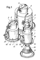
- a socket-lamp structure comprises a tubular wall body 1, which may have different diameter in order to receive different lamps or, however, to form socketed lamps having visible parts of different diameter; the tubular body 1 has an upper part 3 which is intended for receiving the assembly parts of the lamp-holder like the block 5 embodying the terminal board and carrying the lamp-holder 7.
- the lamp-holder 7 respectively all the block, may be adjusted in position by providing a longitudinal slit in the wall 3 and/or in the wall 1 to achieve the lamp-holder fastening in a position axially adjustable along said slit, by means of a pressing screw.
- the tubular body 1 has a flange 10, to which two or more springs 12 are engaged directly on the flange or better in corresponding slits formed in the same flange.
- the springs 12 allow the flange 10 to be engaged by a seal ring 14 in order to finish the socketed lamp.
- This ring may also engage a cone 16 which may be requested in some cases in the socket-lamps.
- two sets of transversal slits 18 may be provided, being longitudinally aligned and stairs-like arranged; the two sets of slits are formed in two diametrically opposite positions.
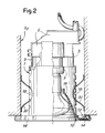
- a U-shaped spring 20 may be inserted, into each set of slits 18, having the intermediate part 20A in the inside of the tubular body and arms 20 which project outwardly of the tubular body wall.
- the two arms of the springs 20 tend to open and are forced towards each another to permit the insertion into the predetermined pair of slits 18 from the inside toward the outside.
- the springs 20 serve to fix the structure of the tubular body 1 with what it includes into the seat receiving it therein.
- the body 1 Upon assembly, the body 1 is engaged into the seat before completing the assembly of the lamp and of the eventual cone as well as the ring, for easily handling the springs.
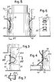
- the springs 20 may be inserted only in part into the slits, as shown in Fig.3, where they may be kept by the presence of shapings 20C, more or less marked, and possibly such as to ensure the sliding along the contrast surfaces.
- the seats may be of two types: one type S2 (Fig.5) is made up of a dug out hole with cylindrical wall; another type S1 is in the form of a hole passing through a panel P (Figs.3 and 4) the thickness of which may vary.
- the springs 20 are arranged as indicated in Fig.5 and biased according to arrows f1 so that to have the assembly inserted into the seat S2 and then make it slide while forcing the spring arms against the wall of seat S2, exerting in this way a friction pressure; alternatively, the springs may be arranged already outwardly projecting and be pressed by opening their upper arms in order to enter the seat and then leave them against it to make them slide in the abutting position of flange 10 against the wall.
- the construction of the lamp structure as a tubular body offers many advantages: it allows a substantial clogging of the holes making up the seats S2 to make use of the interspace for circulation of air or other; it permits to screen the light directed towards the back part of the headlight; it permits to isolate the light source from the neighbouring environment.
- the present headlight has further complementary advantages obtainable through simple constructions, among which: it offers the possibility to adjust the lamp in axial position; the easy replacement of the seal ring; the setting of the connection box; the possibility to make socketed lamps of various sizes with only one head.
Landscapes
- Engineering & Computer Science (AREA)
- General Engineering & Computer Science (AREA)
- Fastening Of Light Sources Or Lamp Holders (AREA)
Applications Claiming Priority (2)
| Application Number | Priority Date | Filing Date | Title |
|---|---|---|---|
| IT1195883U | 1983-12-09 | ||
| IT1195883U IT8311958V0 (it) | 1983-12-09 | 1983-12-09 | Complesso di lume da incassare,con corpo tubolare atto ad essere accolto nella sede |
Publications (2)
| Publication Number | Publication Date |
|---|---|
| EP0145680A2 true EP0145680A2 (de) | 1985-06-19 |
| EP0145680A3 EP0145680A3 (de) | 1985-07-03 |
Family
ID=11138779
Family Applications (1)
| Application Number | Title | Priority Date | Filing Date |
|---|---|---|---|
| EP84830325A Withdrawn EP0145680A3 (de) | 1983-12-09 | 1984-12-03 | Rohrförmige Einbauleuchte |
Country Status (2)
| Country | Link |
|---|---|
| EP (1) | EP0145680A3 (de) |
| IT (1) | IT8311958V0 (de) |
Cited By (5)
| Publication number | Priority date | Publication date | Assignee | Title |
|---|---|---|---|---|
| EP1139018A2 (de) | 2000-03-25 | 2001-10-04 | A. Raymond & Cie | Befestigungsmittel, insbesondere für Einbauleuchten |
| US20100211243A1 (en) * | 2004-03-05 | 2010-08-19 | Samsung Electronics Co., Ltd. Of Suwon-Si | Traveling control method, medium, and apparatus for autonomous navigation |
| EP2157370A3 (de) * | 2008-08-22 | 2010-10-13 | Daxtor APS | Anpassbarer Einsatz |
| ITBO20100460A1 (it) * | 2010-07-22 | 2012-01-23 | Viabizzuno Srl | Faretto regolabile |
| EP4592591A1 (de) * | 2024-01-29 | 2025-07-30 | Zumtobel Lighting GmbH | Kabelrückhalteeinheit und damit ausgestattete leuchte |
Family Cites Families (5)
| Publication number | Priority date | Publication date | Assignee | Title |
|---|---|---|---|---|
| US3099404A (en) * | 1961-11-13 | 1963-07-30 | Markstone Mfg Company | Recessed lighting fixtures |
| US3316399A (en) * | 1962-01-29 | 1967-04-25 | C & M Products Ltd | Pot-light fixture |
| US3801815A (en) * | 1973-02-14 | 1974-04-02 | Marvin Electric Mfg Co | Downlight with multiplier cone |
| US4048491A (en) * | 1974-04-08 | 1977-09-13 | Wessman Leonard A | Recessed lighting fixture |
| FR2497557A1 (fr) * | 1981-01-06 | 1982-07-09 | David Francis | Systeme de spot encastre |
-
1983
- 1983-12-09 IT IT1195883U patent/IT8311958V0/it unknown
-
1984
- 1984-12-03 EP EP84830325A patent/EP0145680A3/de not_active Withdrawn
Cited By (8)
| Publication number | Priority date | Publication date | Assignee | Title |
|---|---|---|---|---|
| EP1139018A2 (de) | 2000-03-25 | 2001-10-04 | A. Raymond & Cie | Befestigungsmittel, insbesondere für Einbauleuchten |
| DE10014967A1 (de) * | 2000-03-25 | 2001-10-04 | Raymond A & Cie | Befestigungmittel, insbesondere für Einbauleuchten |
| DE10014967C2 (de) * | 2000-03-25 | 2002-03-21 | Raymond A & Cie | Befestigungmittel, insbesondere für Einbauleuchten |
| US20100211243A1 (en) * | 2004-03-05 | 2010-08-19 | Samsung Electronics Co., Ltd. Of Suwon-Si | Traveling control method, medium, and apparatus for autonomous navigation |
| EP2157370A3 (de) * | 2008-08-22 | 2010-10-13 | Daxtor APS | Anpassbarer Einsatz |
| ITBO20100460A1 (it) * | 2010-07-22 | 2012-01-23 | Viabizzuno Srl | Faretto regolabile |
| EP4592591A1 (de) * | 2024-01-29 | 2025-07-30 | Zumtobel Lighting GmbH | Kabelrückhalteeinheit und damit ausgestattete leuchte |
| WO2025162702A1 (en) * | 2024-01-29 | 2025-08-07 | Zumtobel Lighting Gmbh | Cable restraint unit and luminaire provided therewith |
Also Published As
| Publication number | Publication date |
|---|---|
| EP0145680A3 (de) | 1985-07-03 |
| IT8311958V0 (it) | 1983-12-09 |
Similar Documents
| Publication | Publication Date | Title |
|---|---|---|
| US6994457B2 (en) | Recessed downlight lighting apparatus | |
| EP0877190B1 (de) | Rohrkupplung | |
| DE102016110303B4 (de) | Schnappverkleidung zum Nachrüsten für Leuchten | |
| DE3516812C2 (de) | ||
| RU2000120540A (ru) | Разъемная быстродействующая муфта с автоматическим указателем правильности ее сборки | |
| RU2002111667A (ru) | Соединительное устройство | |
| US5941628A (en) | Lamp-holder for decorative network type light | |
| GR3015299T3 (en) | Demountable pipe connection. | |
| US4548446A (en) | Articulable joint | |
| US4411054A (en) | Art of installing a sink drain flange assembly capable of supporting a garbage disposal | |
| CA2095963A1 (en) | Mounting arrangement for recessed lighting fixtures | |
| DE3820894A1 (de) | Beleuchtungskoerper | |
| DE69207470T2 (de) | Lüftungsanlage für Beleuchtungseinrichtung von Fahrzeugen | |
| US6455775B1 (en) | Light fixture assembly and installation structure capable of both hanging and suspended applications | |
| DE3021395C2 (de) | Halterung für eine Leuchte mit kugelförmigem Strahler | |
| EP4450866A1 (de) | Aufnahmevorrichtung zur aufnahme einer akkubetriebenen leuchteinheit für eine stehleuchte | |
| AU2004201223A1 (en) | Electrical light assembly, adapter and method | |
| EP0474330B1 (de) | An einem Paneel bzw. an einem Rahmen befestigte Anzeigeleuchten | |
| EP0900975B1 (de) | Haltevorrichtung für einen Reflektor und ein Lichtelement an einem Gehäuse einer Beleuchtungseinrichtung für Fahrzeuge | |
| EP0145680A3 (de) | Rohrförmige Einbauleuchte | |
| DE60116990T2 (de) | Filter-Haltevorrichtung für Beleuchtungseinrichtungen | |
| US3811176A (en) | Method for assembling posts and rails | |
| US3704368A (en) | Mounting device for a light fixture globe | |
| DE102009032461A1 (de) | Vorrichtung zur Befestigung einer Lampe in einer Beleuchtungseinrichtung eines Kraftfahrzeugs | |
| CN216480428U (zh) | 一种便于固定的磁性灯具底座 |
Legal Events
| Date | Code | Title | Description |
|---|---|---|---|
| PUAI | Public reference made under article 153(3) epc to a published international application that has entered the european phase |
Free format text: ORIGINAL CODE: 0009012 |
|
| PUAL | Search report despatched |
Free format text: ORIGINAL CODE: 0009013 |
|
| AK | Designated contracting states |
Designated state(s): BE DE FR GB NL |
|
| AK | Designated contracting states |
Designated state(s): BE DE FR GB NL |
|
| 17P | Request for examination filed |
Effective date: 19851108 |
|
| 17Q | First examination report despatched |
Effective date: 19860526 |
|
| STAA | Information on the status of an ep patent application or granted ep patent |
Free format text: STATUS: THE APPLICATION IS DEEMED TO BE WITHDRAWN |
|
| 18D | Application deemed to be withdrawn |
Effective date: 19870213 |
|
| RIN1 | Information on inventor provided before grant (corrected) |
Inventor name: TARGETTI, PAOLO |