EP0145854A2 - Construction d'un toit - Google Patents
Construction d'un toit Download PDFInfo
- Publication number
- EP0145854A2 EP0145854A2 EP84110764A EP84110764A EP0145854A2 EP 0145854 A2 EP0145854 A2 EP 0145854A2 EP 84110764 A EP84110764 A EP 84110764A EP 84110764 A EP84110764 A EP 84110764A EP 0145854 A2 EP0145854 A2 EP 0145854A2
- Authority
- EP
- European Patent Office
- Prior art keywords
- roof
- profile
- structure according
- roof structure
- rail
- Prior art date
- Legal status (The legal status is an assumption and is not a legal conclusion. Google has not performed a legal analysis and makes no representation as to the accuracy of the status listed.)
- Granted
Links
Images


Classifications
-
- E—FIXED CONSTRUCTIONS
- E04—BUILDING
- E04D—ROOF COVERINGS; SKY-LIGHTS; GUTTERS; ROOF-WORKING TOOLS
- E04D13/00—Special arrangements or devices in connection with roof coverings; Protection against birds; Roof drainage ; Sky-lights
- E04D13/16—Insulating devices or arrangements in so far as the roof covering is concerned, e.g. characterised by the material or composition of the roof insulating material or its integration in the roof structure
- E04D13/1606—Insulation of the roof covering characterised by its integration in the roof structure
- E04D13/1681—Insulating of pre-existing roofs with or without ventilating arrangements
-
- E—FIXED CONSTRUCTIONS
- E04—BUILDING
- E04D—ROOF COVERINGS; SKY-LIGHTS; GUTTERS; ROOF-WORKING TOOLS
- E04D3/00—Roof covering by making use of flat or curved slabs or stiff sheets
- E04D3/36—Connecting; Fastening
- E04D3/3608—Connecting; Fastening for double roof covering or overroofing
-
- E—FIXED CONSTRUCTIONS
- E04—BUILDING
- E04G—SCAFFOLDING; FORMS; SHUTTERING; BUILDING IMPLEMENTS OR AIDS, OR THEIR USE; HANDLING BUILDING MATERIALS ON THE SITE; REPAIRING, BREAKING-UP OR OTHER WORK ON EXISTING BUILDINGS
- E04G23/00—Working measures on existing buildings
- E04G23/02—Repairing, e.g. filling cracks; Restoring; Altering; Enlarging
-
- E—FIXED CONSTRUCTIONS
- E04—BUILDING
- E04G—SCAFFOLDING; FORMS; SHUTTERING; BUILDING IMPLEMENTS OR AIDS, OR THEIR USE; HANDLING BUILDING MATERIALS ON THE SITE; REPAIRING, BREAKING-UP OR OTHER WORK ON EXISTING BUILDINGS
- E04G23/00—Working measures on existing buildings
- E04G23/02—Repairing, e.g. filling cracks; Restoring; Altering; Enlarging
- E04G23/0281—Repairing or restoring roofing or roof covering
Definitions
- the invention relates to a roof construction for the renovation of ventilated roofs to thermally insulated, not ventilated roofs, using and without tearing the existing roof skin from e.g. Asbestos cement carried by purlins.
- the ventilated roof constructions that are still in use and are still in use can no longer be used, or can only be used to a very limited extent, from the point of view of the new thermal insulation regulation. If one wanted to adapt these known roof constructions in accordance with the conditions of the new thermal insulation regulation, then a corresponding, at least 8 cm thick thermal insulation would have to be installed on the underside.
- the disadvantage of such a renovation of existing roofs is that the temperature gradient to the wave crest of the corrugated asbestos cement roof above is very small. As a result, the thermals necessary for ventilation to remove the moisture in use are so low that physical damage must occur here, as is already the case with such Has been the roofs' case, which have been, though still used in gymnastics and sports halls with less insulation.
- the invention is based on the object, the existing corrugated asbestos roof structures as existing roof to a non-ventilated roof, i.e. to convert to a warm roof with the least possible effort using and without tearing the old roof skin.
- the insulating intermediate carrier can either consist of individual insulating pieces, which are attached to the individual stands, or this can consist of a continuous thermal purlin, which is a spatially stable lattice girder forms, as will be described in more detail below.
- the space between the old roof skin and the new roof skin, which advantageously consists of metal sheets, can then either be foamed with a polyurethane foam or lined with mineral wool.
- the stands which may consist of Z angles, for example, are no longer designed with legs that are angled by 90 ° to the central web, but with an angle - corresponding to the roof inclination - that is greater than 90 ° , where the two Z-legs are parallel to each other to take into account the existing roof pitch.
- the load is introduced into the purlin in such a direction that little or no torque is exerted on the purlin.
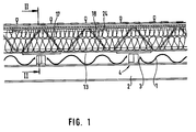
- the old roof skin 1 is made of e.g. Well-asbestos cement carried by a purlin 2, which in turn is supported on supports not shown.
- Round holes 3 are cut into the old roof skin 1, as can be seen in plan view in FIG. 3.
- a stand 4 is pushed, which is formed in the exemplary embodiment from two Z-shaped profile pieces 5, 6, which are screwed alternately on the purlin 2. This has the advantage that, on the one hand, one can get by with relatively small bores 3 and, on the other hand, the load distribution on the purlin is symmetrical.
- this intermediate carrier is designed as a dimensionally stable intermediate carrier, which has a low thermal conductivity from the stand to the new roof skin 12 fastened on it.
- the intermediate carrier 9 has a lower rail 13 which is U-shaped in cross section and whose legs 14, 15 are directed upwards.
- a round rod 16 is welded into each corner of the rail 13, which stiffens the rail 13 from a static point of view and can be made from a thin material.
- V-shaped profile bars 17 are welded to the round bars 16 and extend over the entire length of the beam.
- a further, longitudinal profile bar 18 is welded, which extends over the entire length of the intermediate carrier 9.
- the distance between the V-shaped rods 17 decreases, so that the triangular support obtained results in a spatially stable intermediate support 9 which is of grid-like design.
- the intermediate support 9 is characterized by a high degree of stability in all directions of force application by a minimal expenditure of material, the connections of the rail 13 lying below to the profile bar 18 lying above being made over relatively small cross-sections compared to the longitudinal extension of the intermediate carrier.
- the carrier can be used with relatively low thermal bridges when viewed in the direction of assembly. This is of great advantage for roof structures that place high demands on thermal insulation.
- a U-profile 22 is connected to the intermediate carrier by means of a clamping device consisting of screws 19, 20 and a plate 21.
- the legs 23 of the U-profile are angled downwards and form abutments for the attachment of the new roof skin 12, which in the simplest case is attached to the U-profile 22 by means of clips 24.
- the screw heads of the screws 19, 20 are accessible from the outside of the U-profile and engage in threaded holes in the plate 21.
- two insulating pieces 25, 26 are arranged, which are pressed against the profile bar 18 by the clamping device.
- this results in a further insulation of the U-profile with respect to the stand 4 and, furthermore, this arrangement allows the U-profile to be inclined relative to the intermediate support 9 in accordance with the desired roof pitch. This enables adaptation to the respective roof pitch without any particular difficulties.
- a new heat-insulating and not ventilated roof construction can be created without great effort and in particular without dismantling the existing old roof skin.
- this construction can not only be obtained with simple means, but it also has the advantage that the Activities in the hall when converting the roof are not affected.
- FIGS. 4 and 5 differs from that of FIGS. 1 to 3 essentially in that the stand 4, which here also consists of two Z-shaped angled profile pieces 5 and 6, with the stand 2 over Screws 27 are connected, is made higher, so that its legs 7, 8 reach higher over the roof skin 1 than in the embodiment according to FIGS. 1 to 3.
- the intermediate carrier 9 is reduced to two insulating pieces 3 9 , 40, on which a rail 28 is placed, which extends over the entire length of the purlin 2 and which has a U-shaped profile in cross section.
- the roof skin 12 As such, it consists of metal sheets which are angled upwards at their edges 36 and are pushed over one another in a known manner, so that a tight connection between the two is obtained. It is also conceivable to place an intermediate plate 37 on the old roof skin, if the insulating layer 38 is to have a defined termination at the bottom, which should not match the surface of the old roof skin.
- FIG. 6 corresponds essentially to that of FIGS. 4 and 5, with the only modification that the stand 4, which in turn is formed from two Z-shaped profile pieces 5 and 6, forms an angle with its legs, which is greater than 90 °. It is hereby achieved that in the case of more inclined roofs, the introduction of force runs through the center of the purlin 2 and not at a distance from it, so that a moment is exerted on it.
- the angle of the legs of the Z-shaped profile pieces can be chosen according to the inclination of the roof and the height of the new roof structure. This eliminates the otherwise inevitable leverage effect on the substructure.
Landscapes
- Engineering & Computer Science (AREA)
- Architecture (AREA)
- Civil Engineering (AREA)
- Structural Engineering (AREA)
- Mechanical Engineering (AREA)
- Chemical & Material Sciences (AREA)
- Chemical Kinetics & Catalysis (AREA)
- Electrochemistry (AREA)
- Roof Covering Using Slabs Or Stiff Sheets (AREA)
Priority Applications (1)
| Application Number | Priority Date | Filing Date | Title |
|---|---|---|---|
| AT84110764T ATE50015T1 (de) | 1983-12-06 | 1984-09-10 | Dachkonstruktion. |
Applications Claiming Priority (4)
| Application Number | Priority Date | Filing Date | Title |
|---|---|---|---|
| DE19833343984 DE3343984A1 (de) | 1983-12-06 | 1983-12-06 | Traeger fuer dachkonstruktionen, insbesondere fuer flachdaecher |
| DE3343984 | 1983-12-06 | ||
| DE3421871 | 1984-06-13 | ||
| DE19843421871 DE3421871A1 (de) | 1984-06-13 | 1984-06-13 | Dachkonstruktion |
Publications (3)
| Publication Number | Publication Date |
|---|---|
| EP0145854A2 true EP0145854A2 (fr) | 1985-06-26 |
| EP0145854A3 EP0145854A3 (en) | 1987-10-28 |
| EP0145854B1 EP0145854B1 (fr) | 1990-01-31 |
Family
ID=25816184
Family Applications (1)
| Application Number | Title | Priority Date | Filing Date |
|---|---|---|---|
| EP84110764A Expired - Lifetime EP0145854B1 (fr) | 1983-12-06 | 1984-09-10 | Construction d'un toit |
Country Status (3)
| Country | Link |
|---|---|
| US (1) | US4691482A (fr) |
| EP (1) | EP0145854B1 (fr) |
| DE (1) | DE3481207D1 (fr) |
Cited By (2)
| Publication number | Priority date | Publication date | Assignee | Title |
|---|---|---|---|---|
| WO1986003796A1 (fr) * | 1984-12-19 | 1986-07-03 | Laramore Larry W | Systeme de charpente et de piedestal pour la construction d'un toit supplementaire |
| FR2614054A1 (fr) * | 1987-04-15 | 1988-10-21 | Haironville Forges | Procede de construction de parois de batiments |
Families Citing this family (15)
| Publication number | Priority date | Publication date | Assignee | Title |
|---|---|---|---|---|
| JP3717171B2 (ja) * | 2003-05-22 | 2005-11-16 | 松本建工株式会社 | 住宅用遮熱材 |
| JP3717172B2 (ja) * | 2003-05-29 | 2005-11-16 | 松本建工株式会社 | 住宅用遮熱材 |
| WO2005058744A2 (fr) | 2003-12-11 | 2005-06-30 | Gregory Lambrecht | Dispositif et procede d'extraction et de conservation du vin |
| US9010588B2 (en) | 2012-05-02 | 2015-04-21 | Coravin, Inc. | Method and apparatus for engaging a beverage extraction device with a container |
| CN103541464B (zh) * | 2012-07-10 | 2016-05-11 | 重庆前鼎金属材料有限公司 | 一种带有凸台的网板及其筑墙方法 |
| US8925756B2 (en) | 2012-08-08 | 2015-01-06 | Coravin, Inc. | Method and apparatus for gas cylinder sealing |
| US9016502B2 (en) | 2012-10-09 | 2015-04-28 | Coravin, Inc. | Method and apparatus for gas cylinder sealing |
| US8910829B2 (en) | 2012-10-09 | 2014-12-16 | Coravin, Inc. | Method and apparatus for beverage extraction needle guiding |
| US9016517B2 (en) | 2012-11-07 | 2015-04-28 | Coravin, Inc. | Method and apparatus for beverage extraction needle force indication |
| US9139411B2 (en) | 2013-03-11 | 2015-09-22 | Coravin, Inc. | Method and apparatus for beverage extraction with a multi-function valve |
| ES2667952T3 (es) | 2013-06-14 | 2018-05-16 | Coravin, Inc. | Aparato para extracción de bebidas con acceso de cilindro de gas mejorado |
| US9810375B2 (en) | 2015-06-30 | 2017-11-07 | Coravin, Inc. | Engagement of gas cylinder with gas dispenser |
| USD1053389S1 (en) | 2020-03-26 | 2024-12-03 | Nucor Corporation | Support member for roof panel offset |
| US11536034B2 (en) | 2020-03-26 | 2022-12-27 | Nucor Corporation | Insulated roof systems, support members thereof, and method of installing |
| US12491480B2 (en) * | 2021-10-08 | 2025-12-09 | Coravin, Inc. | Pressurized gas supply and gas cylinder |
Family Cites Families (16)
| Publication number | Priority date | Publication date | Assignee | Title |
|---|---|---|---|---|
| US3210896A (en) * | 1963-08-20 | 1965-10-12 | Kenneth D Detman | Weather protector for roofs |
| US4081938A (en) * | 1976-12-13 | 1978-04-04 | Ralph Bertacchi | Standoff insulated panel mounting |
| US4314428A (en) * | 1978-11-17 | 1982-02-09 | Bromwell Michael A J | Overcladding structure for a roof |
| US4277926A (en) * | 1979-05-30 | 1981-07-14 | The Celotex Corporation | Vented insulation system for existing structure |
| GB2051910A (en) * | 1979-06-27 | 1981-01-21 | Cape Insulation Services Ltd | Roofing |
| US4248021A (en) * | 1979-08-22 | 1981-02-03 | H. H. Robertson Company | Support means for wall or roof structure |
| US4288951A (en) * | 1979-11-14 | 1981-09-15 | Scientific Applications Incorporated | Auxiliary insulated roof system |
| US4494343A (en) * | 1980-03-03 | 1985-01-22 | The Celotex Corporation | Structure for retrofitting corrugated building exteriors |
| US4423572A (en) * | 1980-09-22 | 1984-01-03 | Tor Edward S | Water-tight insulated roof construction for house |
| GB2092202B (en) * | 1981-01-29 | 1985-02-13 | Itw Ltd | Overroofing of buildings |
| DE3128134A1 (de) * | 1981-07-16 | 1983-02-03 | Grünzweig + Hartmann und Glasfaser AG, 6700 Ludwigshafen | Vorrichtung zur waermedaemmung von dachflaechen |
| DE3214890A1 (de) * | 1982-04-22 | 1983-11-03 | Anton Grimm GmbH, 6951 Limbach | Dachauflage |
| US4495741A (en) * | 1982-07-26 | 1985-01-29 | Westeel-Rosco Limited-Westeel-Rosco Limitee | Adjustable spacer kit of parts, and building wall or roof structure incorporating the same |
| US4435926A (en) * | 1982-09-01 | 1984-03-13 | Struben Francis L | Ridge roof |
| US4445305A (en) * | 1982-09-27 | 1984-05-01 | Orie Sr Thomas A | Insulating secondary roof system |
| DE3306275A1 (de) * | 1983-02-23 | 1984-08-30 | Erwin 4795 Delbrück Küpper | Verfahren zur nachtraeglichen aeusseren isolierung von daechern und nach dem verfahren hergestellte isolierung von daechern |
-
1984
- 1984-09-10 EP EP84110764A patent/EP0145854B1/fr not_active Expired - Lifetime
- 1984-09-10 DE DE8484110764T patent/DE3481207D1/de not_active Expired - Fee Related
- 1984-11-15 US US06/671,658 patent/US4691482A/en not_active Expired - Lifetime
Cited By (3)
| Publication number | Priority date | Publication date | Assignee | Title |
|---|---|---|---|---|
| WO1986003796A1 (fr) * | 1984-12-19 | 1986-07-03 | Laramore Larry W | Systeme de charpente et de piedestal pour la construction d'un toit supplementaire |
| US4631878A (en) * | 1984-12-19 | 1986-12-30 | Laramore Larry W | Pedestal and framing system for supplemental roof construction |
| FR2614054A1 (fr) * | 1987-04-15 | 1988-10-21 | Haironville Forges | Procede de construction de parois de batiments |
Also Published As
| Publication number | Publication date |
|---|---|
| US4691482A (en) | 1987-09-08 |
| DE3481207D1 (de) | 1990-03-08 |
| EP0145854B1 (fr) | 1990-01-31 |
| EP0145854A3 (en) | 1987-10-28 |
Similar Documents
| Publication | Publication Date | Title |
|---|---|---|
| EP0145854B1 (fr) | Construction d'un toit | |
| DE3213358A1 (de) | Vorrichtung zur befestigung einer first- oder gratlatte an einem dachstuhl | |
| DE69827084T2 (de) | Doppellagiges Blechdach mit einer isolierenden Zwischenlage aus abrollbarem Filz | |
| DE10147831B4 (de) | Ständerwand | |
| EP0108222A2 (fr) | Structure de support | |
| DE3032359C2 (de) | Unterkonstruktion zur Befestigung einer Wandbekleidung | |
| DE3622648C2 (fr) | ||
| EP0649951B1 (fr) | Coffrage pour béton | |
| DE8309679U1 (de) | Gewellte dachplatte | |
| DE3421871A1 (de) | Dachkonstruktion | |
| DE68914009T2 (de) | Befestigungsvorrichtung für Dachziegel. | |
| DE8006695U1 (de) | Druckuebertrager | |
| AT345525B (de) | Blechprofil, vorzugsweise fuer aussendachkonstruktionen | |
| DE3247053C2 (de) | Vorgehängte Außenwand | |
| DE102023005386B4 (de) | Bausatz zur Aufständerung von Solarmodulen | |
| EP0052158A1 (fr) | Bloc-support pour revêtements de façades | |
| DE3039112A1 (de) | Vorrichtung zum abstuetzen einer dachkonstruktion | |
| DE1659280A1 (de) | Vorgearbeitetes Dachelement | |
| EP1019597A1 (fr) | Structure porteuse destinee au montage d'une deuxieme toiture sur une premiere toiture de plaques ondulees | |
| DE69129904T2 (de) | Dachkonstruktion | |
| DE3011181C2 (de) | Randeinfassung für Flachdächer oder dergleichen | |
| DE2058167C3 (de) | Vorrichtung zum Abstützen von die äußere Schale eines zweischaligen Flachdaches bildenden Dacheindeckungsplatten | |
| CH663053A5 (de) | Traeger fuer dachkonstruktionen, insbesondere fuer flachdaecher. | |
| DE10212448A1 (de) | Profilelement mit einer Schiene und einer Hafte, Dachsystem und Verfahren zum Eindecken | |
| DE9107439U1 (de) | Dachtragwerk |
Legal Events
| Date | Code | Title | Description |
|---|---|---|---|
| PUAI | Public reference made under article 153(3) epc to a published international application that has entered the european phase |
Free format text: ORIGINAL CODE: 0009012 |
|
| AK | Designated contracting states |
Designated state(s): AT BE CH DE FR GB IT LI LU NL SE |
|
| PUAL | Search report despatched |
Free format text: ORIGINAL CODE: 0009013 |
|
| AK | Designated contracting states |
Kind code of ref document: A3 Designated state(s): AT BE CH DE FR GB IT LI LU NL SE |
|
| 17P | Request for examination filed |
Effective date: 19871120 |
|
| 17Q | First examination report despatched |
Effective date: 19890116 |
|
| GRAA | (expected) grant |
Free format text: ORIGINAL CODE: 0009210 |
|
| AK | Designated contracting states |
Kind code of ref document: B1 Designated state(s): AT BE CH DE FR GB IT LI LU NL SE |
|
| ITF | It: translation for a ep patent filed | ||
| REF | Corresponds to: |
Ref document number: 50015 Country of ref document: AT Date of ref document: 19900215 Kind code of ref document: T |
|
| REF | Corresponds to: |
Ref document number: 3481207 Country of ref document: DE Date of ref document: 19900308 |
|
| GBT | Gb: translation of ep patent filed (gb section 77(6)(a)/1977) | ||
| ET | Fr: translation filed | ||
| PLBE | No opposition filed within time limit |
Free format text: ORIGINAL CODE: 0009261 |
|
| STAA | Information on the status of an ep patent application or granted ep patent |
Free format text: STATUS: NO OPPOSITION FILED WITHIN TIME LIMIT |
|
| 26N | No opposition filed | ||
| ITTA | It: last paid annual fee | ||
| EPTA | Lu: last paid annual fee | ||
| EAL | Se: european patent in force in sweden |
Ref document number: 84110764.2 |
|
| PGFP | Annual fee paid to national office [announced via postgrant information from national office to epo] |
Ref country code: AT Payment date: 19990928 Year of fee payment: 16 |
|
| PGFP | Annual fee paid to national office [announced via postgrant information from national office to epo] |
Ref country code: SE Payment date: 20000810 Year of fee payment: 17 |
|
| PGFP | Annual fee paid to national office [announced via postgrant information from national office to epo] |
Ref country code: LU Payment date: 20000814 Year of fee payment: 17 |
|
| PGFP | Annual fee paid to national office [announced via postgrant information from national office to epo] |
Ref country code: BE Payment date: 20000823 Year of fee payment: 17 |
|
| PGFP | Annual fee paid to national office [announced via postgrant information from national office to epo] |
Ref country code: FR Payment date: 20000828 Year of fee payment: 17 |
|
| PGFP | Annual fee paid to national office [announced via postgrant information from national office to epo] |
Ref country code: GB Payment date: 20000906 Year of fee payment: 17 |
|
| PG25 | Lapsed in a contracting state [announced via postgrant information from national office to epo] |
Ref country code: AT Free format text: LAPSE BECAUSE OF NON-PAYMENT OF DUE FEES Effective date: 20000910 |
|
| PGFP | Annual fee paid to national office [announced via postgrant information from national office to epo] |
Ref country code: NL Payment date: 20000930 Year of fee payment: 17 |
|
| PG25 | Lapsed in a contracting state [announced via postgrant information from national office to epo] |
Ref country code: LU Free format text: LAPSE BECAUSE OF NON-PAYMENT OF DUE FEES Effective date: 20010910 Ref country code: GB Free format text: LAPSE BECAUSE OF NON-PAYMENT OF DUE FEES Effective date: 20010910 |
|
| PG25 | Lapsed in a contracting state [announced via postgrant information from national office to epo] |
Ref country code: SE Free format text: LAPSE BECAUSE OF NON-PAYMENT OF DUE FEES Effective date: 20010911 |
|
| PGFP | Annual fee paid to national office [announced via postgrant information from national office to epo] |
Ref country code: CH Payment date: 20010925 Year of fee payment: 18 |
|
| PG25 | Lapsed in a contracting state [announced via postgrant information from national office to epo] |
Ref country code: BE Free format text: LAPSE BECAUSE OF NON-PAYMENT OF DUE FEES Effective date: 20010930 |
|
| PGFP | Annual fee paid to national office [announced via postgrant information from national office to epo] |
Ref country code: DE Payment date: 20011025 Year of fee payment: 18 |
|
| BERE | Be: lapsed |
Owner name: HEINEMANN HORST DIETER Effective date: 20010930 |
|
| PG25 | Lapsed in a contracting state [announced via postgrant information from national office to epo] |
Ref country code: NL Free format text: LAPSE BECAUSE OF NON-PAYMENT OF DUE FEES Effective date: 20020401 |
|
| GBPC | Gb: european patent ceased through non-payment of renewal fee |
Effective date: 20010910 |
|
| EUG | Se: european patent has lapsed |
Ref document number: 84110764.2 |
|
| PG25 | Lapsed in a contracting state [announced via postgrant information from national office to epo] |
Ref country code: FR Free format text: LAPSE BECAUSE OF NON-PAYMENT OF DUE FEES Effective date: 20020531 |
|
| NLV4 | Nl: lapsed or anulled due to non-payment of the annual fee |
Effective date: 20020401 |
|
| REG | Reference to a national code |
Ref country code: FR Ref legal event code: ST |
|
| PG25 | Lapsed in a contracting state [announced via postgrant information from national office to epo] |
Ref country code: LI Free format text: LAPSE BECAUSE OF NON-PAYMENT OF DUE FEES Effective date: 20020930 Ref country code: CH Free format text: LAPSE BECAUSE OF NON-PAYMENT OF DUE FEES Effective date: 20020930 |
|
| PG25 | Lapsed in a contracting state [announced via postgrant information from national office to epo] |
Ref country code: DE Free format text: LAPSE BECAUSE OF NON-PAYMENT OF DUE FEES Effective date: 20030401 |
|
| REG | Reference to a national code |
Ref country code: CH Ref legal event code: PL |
|
| NLV4 | Nl: lapsed or anulled due to non-payment of the annual fee |
Effective date: 20020401 |