EP0145877B1 - Photomètre pour l'analyse en continu d'un milieu (gaz ou liquide) - Google Patents
Photomètre pour l'analyse en continu d'un milieu (gaz ou liquide) Download PDFInfo
- Publication number
- EP0145877B1 EP0145877B1 EP84112134A EP84112134A EP0145877B1 EP 0145877 B1 EP0145877 B1 EP 0145877B1 EP 84112134 A EP84112134 A EP 84112134A EP 84112134 A EP84112134 A EP 84112134A EP 0145877 B1 EP0145877 B1 EP 0145877B1
- Authority
- EP
- European Patent Office
- Prior art keywords
- light
- medium
- beams
- photometer
- optical
- Prior art date
- Legal status (The legal status is an assumption and is not a legal conclusion. Google has not performed a legal analysis and makes no representation as to the accuracy of the status listed.)
- Expired
Links
- 239000007788 liquid Substances 0.000 title claims description 9
- 238000010521 absorption reaction Methods 0.000 claims description 31
- 230000003287 optical effect Effects 0.000 claims description 18
- 230000003595 spectral effect Effects 0.000 claims description 7
- 239000004020 conductor Substances 0.000 claims 6
- 241001212149 Cathetus Species 0.000 claims 1
- 230000005855 radiation Effects 0.000 description 11
- 238000012545 processing Methods 0.000 description 8
- 239000000203 mixture Substances 0.000 description 6
- 239000000835 fiber Substances 0.000 description 5
- 239000007789 gas Substances 0.000 description 5
- 238000000034 method Methods 0.000 description 5
- 239000013307 optical fiber Substances 0.000 description 4
- 239000000126 substance Substances 0.000 description 4
- 230000008033 biological extinction Effects 0.000 description 3
- 238000011109 contamination Methods 0.000 description 3
- 238000012937 correction Methods 0.000 description 3
- 238000006073 displacement reaction Methods 0.000 description 3
- 238000005259 measurement Methods 0.000 description 3
- 238000000862 absorption spectrum Methods 0.000 description 2
- 230000012447 hatching Effects 0.000 description 2
- 230000035945 sensitivity Effects 0.000 description 2
- 230000032683 aging Effects 0.000 description 1
- 238000004364 calculation method Methods 0.000 description 1
- 230000001419 dependent effect Effects 0.000 description 1
- 238000013461 design Methods 0.000 description 1
- 238000001514 detection method Methods 0.000 description 1
- 230000000694 effects Effects 0.000 description 1
- 239000012535 impurity Substances 0.000 description 1
- 238000011835 investigation Methods 0.000 description 1
- 239000011159 matrix material Substances 0.000 description 1
- 230000005693 optoelectronics Effects 0.000 description 1
- 239000002245 particle Substances 0.000 description 1
- 230000000149 penetrating effect Effects 0.000 description 1
- 230000000737 periodic effect Effects 0.000 description 1
- 230000033764 rhythmic process Effects 0.000 description 1
- 230000001360 synchronised effect Effects 0.000 description 1
- 230000007704 transition Effects 0.000 description 1
- 238000011144 upstream manufacturing Methods 0.000 description 1
- XLYOFNOQVPJJNP-UHFFFAOYSA-N water Substances O XLYOFNOQVPJJNP-UHFFFAOYSA-N 0.000 description 1
Images

Classifications
-
- G—PHYSICS
- G01—MEASURING; TESTING
- G01N—INVESTIGATING OR ANALYSING MATERIALS BY DETERMINING THEIR CHEMICAL OR PHYSICAL PROPERTIES
- G01N21/00—Investigating or analysing materials by the use of optical means, i.e. using sub-millimetre waves, infrared, visible or ultraviolet light
- G01N21/17—Systems in which incident light is modified in accordance with the properties of the material investigated
- G01N21/25—Colour; Spectral properties, i.e. comparison of effect of material on the light at two or more different wavelengths or wavelength bands
- G01N21/31—Investigating relative effect of material at wavelengths characteristic of specific elements or molecules, e.g. atomic absorption spectrometry
-
- G—PHYSICS
- G01—MEASURING; TESTING
- G01N—INVESTIGATING OR ANALYSING MATERIALS BY DETERMINING THEIR CHEMICAL OR PHYSICAL PROPERTIES
- G01N21/00—Investigating or analysing materials by the use of optical means, i.e. using sub-millimetre waves, infrared, visible or ultraviolet light
- G01N21/17—Systems in which incident light is modified in accordance with the properties of the material investigated
- G01N21/25—Colour; Spectral properties, i.e. comparison of effect of material on the light at two or more different wavelengths or wavelength bands
- G01N21/255—Details, e.g. use of specially adapted sources, lighting or optical systems
-
- G—PHYSICS
- G01—MEASURING; TESTING
- G01N—INVESTIGATING OR ANALYSING MATERIALS BY DETERMINING THEIR CHEMICAL OR PHYSICAL PROPERTIES
- G01N21/00—Investigating or analysing materials by the use of optical means, i.e. using sub-millimetre waves, infrared, visible or ultraviolet light
- G01N21/84—Systems specially adapted for particular applications
- G01N21/85—Investigating moving fluids or granular solids
- G01N21/8507—Probe photometers, i.e. with optical measuring part dipped into fluid sample
-
- G—PHYSICS
- G01—MEASURING; TESTING
- G01J—MEASUREMENT OF INTENSITY, VELOCITY, SPECTRAL CONTENT, POLARISATION, PHASE OR PULSE CHARACTERISTICS OF INFRARED, VISIBLE OR ULTRAVIOLET LIGHT; COLORIMETRY; RADIATION PYROMETRY
- G01J3/00—Spectrometry; Spectrophotometry; Monochromators; Measuring colours
- G01J3/28—Investigating the spectrum
- G01J3/2803—Investigating the spectrum using photoelectric array detector
-
- G—PHYSICS
- G01—MEASURING; TESTING
- G01N—INVESTIGATING OR ANALYSING MATERIALS BY DETERMINING THEIR CHEMICAL OR PHYSICAL PROPERTIES
- G01N21/00—Investigating or analysing materials by the use of optical means, i.e. using sub-millimetre waves, infrared, visible or ultraviolet light
- G01N21/01—Arrangements or apparatus for facilitating the optical investigation
- G01N21/15—Preventing contamination of the components of the optical system or obstruction of the light path
- G01N2021/154—Ultrasonic cleaning
-
- G—PHYSICS
- G01—MEASURING; TESTING
- G01N—INVESTIGATING OR ANALYSING MATERIALS BY DETERMINING THEIR CHEMICAL OR PHYSICAL PROPERTIES
- G01N21/00—Investigating or analysing materials by the use of optical means, i.e. using sub-millimetre waves, infrared, visible or ultraviolet light
- G01N21/17—Systems in which incident light is modified in accordance with the properties of the material investigated
- G01N21/25—Colour; Spectral properties, i.e. comparison of effect of material on the light at two or more different wavelengths or wavelength bands
- G01N21/31—Investigating relative effect of material at wavelengths characteristic of specific elements or molecules, e.g. atomic absorption spectrometry
- G01N21/314—Investigating relative effect of material at wavelengths characteristic of specific elements or molecules, e.g. atomic absorption spectrometry with comparison of measurements at specific and non-specific wavelengths
- G01N2021/3181—Investigating relative effect of material at wavelengths characteristic of specific elements or molecules, e.g. atomic absorption spectrometry with comparison of measurements at specific and non-specific wavelengths using LEDs
-
- G—PHYSICS
- G01—MEASURING; TESTING
- G01N—INVESTIGATING OR ANALYSING MATERIALS BY DETERMINING THEIR CHEMICAL OR PHYSICAL PROPERTIES
- G01N21/00—Investigating or analysing materials by the use of optical means, i.e. using sub-millimetre waves, infrared, visible or ultraviolet light
- G01N21/01—Arrangements or apparatus for facilitating the optical investigation
- G01N21/15—Preventing contamination of the components of the optical system or obstruction of the light path
-
- G—PHYSICS
- G01—MEASURING; TESTING
- G01N—INVESTIGATING OR ANALYSING MATERIALS BY DETERMINING THEIR CHEMICAL OR PHYSICAL PROPERTIES
- G01N21/00—Investigating or analysing materials by the use of optical means, i.e. using sub-millimetre waves, infrared, visible or ultraviolet light
- G01N21/17—Systems in which incident light is modified in accordance with the properties of the material investigated
- G01N21/25—Colour; Spectral properties, i.e. comparison of effect of material on the light at two or more different wavelengths or wavelength bands
- G01N21/31—Investigating relative effect of material at wavelengths characteristic of specific elements or molecules, e.g. atomic absorption spectrometry
- G01N21/314—Investigating relative effect of material at wavelengths characteristic of specific elements or molecules, e.g. atomic absorption spectrometry with comparison of measurements at specific and non-specific wavelengths
-
- G—PHYSICS
- G01—MEASURING; TESTING
- G01N—INVESTIGATING OR ANALYSING MATERIALS BY DETERMINING THEIR CHEMICAL OR PHYSICAL PROPERTIES
- G01N2201/00—Features of devices classified in G01N21/00
- G01N2201/06—Illumination; Optics
- G01N2201/066—Modifiable path; multiple paths in one sample
-
- G—PHYSICS
- G01—MEASURING; TESTING
- G01N—INVESTIGATING OR ANALYSING MATERIALS BY DETERMINING THEIR CHEMICAL OR PHYSICAL PROPERTIES
- G01N2201/00—Features of devices classified in G01N21/00
- G01N2201/08—Optical fibres; light guides
Definitions
- the invention relates to a photometer with the features mentioned in the preamble of claim 1 or claim 2.
- EP-OS-0 039 088 describes a measuring arrangement for determining the concentration of dissolved organic substances in a liquid. It comprises a radiation source and a filter device which alternately supplies radiation in two different spectral ranges to a measuring section in a measuring vessel filled with sample liquid. A radiation-permeable displacement body shortens the optically effective path length in the sample liquid to a second path length. The displacement body is displaced; with the help of a drive and a control disc.
- JA-A-5 868 645 describes a method for measuring the concentration of particles in a gas stream using a
- the optical path length of the light beam in the medium is periodically changed by periodic movements of the light guide cable.
- a detector detects the radiation at two defined path lengths, which are determined by the maximum and minimum distance when the light guide cable vibrates given is.
- DE-AS-2 521 934 describes a photometer that works on the autocollimation principle.
- This photometer is equipped with three optical filters, each of which is tuned to a specific wavelength, so that it is possible to determine three substance components of a gas mixture.
- This photometer is disadvantageous insofar as it cannot be expanded or modified as desired in order to detect a larger number of measuring components or to carry out any cross sensitivity corrections.
- contamination of the components in the measuring section, such as windows and reflectors cannot be exactly compensated for in this known photometer.
- a measuring arrangement for determining the radiation absorption in a liquid or gaseous medium is known, which is designed so that both the measuring section and the reference section lie in the measuring medium. With this measuring arrangement, however, the detection of several components of a substance mixture is not possible.
- the invention has for its object to provide a continuously operating photometer of the type mentioned according to the wavelength comparison method for gas or liquid analysis, in particular in a process stream, which allows, in addition to drift and aging of optical components, the influences of those in the measuring medium existing impurities, the absorption of which depends on the wavelength, and which at the same time ensures that several components of a substance mixture are detected in real time.
- Such cases should also be included in which the absorption spectra of a measuring component and several accompanying components overlap, which necessitates a correction to eliminate the interferences.
- the photometer should work in the medium without any mechanically moving parts.
- the photometer designed according to the invention can be used to analyze any medium that consists of at least two components.
- the photometer can be constructed in such a way that two alternately switched-on light sources of different frequencies are provided, each of the two light beams being divided into two partial beams before entering the medium to be analyzed, which impinge on two separate photo receivers after leaving the medium in order to generate the signal pair. which are sensitive in the spectral ranges of the light of both light sources.
- the partial beams in the medium pass through two parallel absorption sections of different lengths at the same time.
- the situation is simple if a two-part optical fiber bundle is provided to split the light beam in two. It is also possible to use inclined mirrors for this.
- the light beam strikes a partially transmissive mirror, which sends part of the light into the medium and directs a part onto a second mirror, which sends the second partial beam into the medium.
- a photometer that works with light sources of different wavelengths can advantageously be developed in such a way that the two light sources consist of two light bulbs arranged at right angles to one another with an upstream interference filter, which guide their rays of a predetermined frequency through a semitransparent mirror via a collimator lens to an optical fiber bundle.
- the light cone leaving the collimator lens is adapted to the respective conditions, for which purpose an aperture with an adjustable aperture can be provided.
- the fiber bundle conducts the light into a container containing the medium to be analyzed.
- the light fiber bundle is divided into two branches, to which two light guide rods are connected, which guide the two light beams generated in this way from each light source to the medium.
- the lamps, interference filter together with the partially transparent mirror, the collimator lens and the diaphragm are combined to form one unit.
- One embodiment of the invention is that in a photometer that is to be analyzed Mixture penetrating input light beam is fed through an optical waveguide in the medium to an optical deflection element which reflects the input light beam in such a way that part of the reflected light after passing through a short absorption section from a first light guide and another part of the reflected light after passing through a longer absorption section from a second Light guide is added.
- the light guides for the partial beams feed the different signals produced by absorption to a processing device; there the signals for determining the concentration of the components are linked to one another. The situation is very simple if light guide rods are used as light guides.
- a prism with mirrored cathets will be preferred.
- the arrangement of a prism has the advantage that the light guide for the input light beam can be coupled directly to the surface of the prism. This creates no transition zone.
- the light guides are connected to the prism to form a compact structural unit that can easily be inserted into a container through which the medium to be analyzed flows. It is possible to combine the resulting sensor with a radiation source. In this way, an analyzer for gases or liquids is created with a height of approximately 30 cm and a diameter of less than 20 cm.
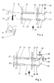
- the photometer works according to the autocollimation process.
- the rays emanating from the broadband radiation source 1 are bundled by the collimator lens 2 and reach the beam guiding device 4 via the beam splitter 3 and from there via the absorption path 5 to the reflector 6.
- the reflection path 5 is located directly in the medium to be analyzed, which is the pipeline 7 flows through.
- the length of the absorption path 5 is determined by the distance of the reflector 6 from the end of the beam guiding device 4 on the reflector side.
- the reflector 6 throws the beams through the beam guide 4 back to the beam splitter 3, which the beams turns and directs through a gap 8 on the prism 9.
- the polychromatic rays are dispersed.
- the dispersed light is imaged on a detector 10, which consists of individual photo receivers that are sensitive in the spectral range of interest. Each photo receiver sends a signal assigned to the respective wavelength into the signal processing device 11, which is connected to the control electronics 12.
- the display device 13 is also connected to the signal processing device 11.
- the intensity for the reference path I 1 is denoted by I1 l n
- the intensity for the measuring path 1 2 by I2 l n.
- the length I in equation 3 must be replaced by (1 2 - I 1 ), In by l2 l n, and o l n by I 1 l n .
- the result is the equation to be given to the signal processing unit 11: reflected.
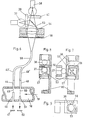
- the partial beam 22 runs through the medium on the path 25 and leaves the container 18 through the light guide device 24.
- the part of the light that penetrates the mirror 21 falls on the inclined mirror 26, which transmits all the light striking it as a partial beam 27 through the light guide device 28 into the container 18.
- the partial beam 27 passes through the path 29 in the medium and leaves the container 18 through the light guide device 30.
- the path 29 is substantially longer than the path 25.
- a diaphragm wheel 31 is arranged in the path of the partial beams 22 and 27 and interrupts the partial sections periodically in phase opposition.
- the inclined mirrors 32 and 33 are provided, which steer the partial beams 22 and 27 in the direction of the prism 34.
- the dispersing light 35 of the prism 34 is received by a detector line 36, the individual photo receivers of which are sensitive in the spectral range of interest.
- the signal processing takes place in the same way as described with the aid of the photometer according to FIG. 2.
- the photometer to be used for analyzing a multi-component medium according to FIG. 5 is equipped with two light bulbs 37 and 38.
- Interference filters 39 and 40 are provided in front of the incandescent lamps 37 and 38 in order to generate light beams of different frequencies.
- the light bulbs 37 and 38 are controlled by an electronic transmitter so that they alternately send light rays onto the partially transparent mirror 41 and the reflecting mirror 42.
- the light reflected by the mirror 41 enters as a partial beam 43 through the light guide 44 into the container 18, which the medium, for. B. a gas flows in the direction of arrow 19.
- This partial beam 43 passes through the medium on the path 45, enters the light-guiding device 46 through which it leaves the container 18 and strikes the photoelectric receiver 47, which is sensitive in the spectral range of both light beams transmitted by the interference filters 39 and 40.
- the part of the light rays passing through the tell-transparent mirror 41 is reflected by the inclined mirror 42 through the light-guiding device 48 into the container 18 as a partial ray 49.
- the partial beam 49 passes through the path 50 in the medium to be analyzed, leaves the container 18 through the light guide device 51 and strikes the photoelectric receiver 52 which, like the photoelectric receiver 47, is sensitive in the spectral range of both light beams transmitted by the interference filters 39 and 40.
- An electronic switch (not shown) is assigned to the photoelectric receivers 47 and 52. which are followed by two electronic processing stages, in particular two logarithmic differential amplifiers.
- the electronic switch is synchronized with the electronic transmitter for lamps 37 and 38.
- the electronic switch feeds the signals of the photoelectric receivers 47 and 52 in phase opposition to one of these electronic processing stages.
- the photometer explained with reference to FIG. 5 can be used in particular for the analysis of a medium which consists of two components.
- two light bulbs 37 and 38 are provided as light sources.
- the light from the incandescent lamp 37 is directed onto the collimator lens 54 by the interference fifter 39 and the partially transparent mirror 53.
- the light from the incandescent lamp 38 is also passed through the interference filter 40 and the mirror 53 to the collimating lens 54.
- the interference filter 39 is arranged in the pocket 55; the interference fifter 40 is arranged in the pocket 56.
- the incandescent lamps 37 and 38 are arranged at right angles to one another.
- the collimator lens is taken in the version 57.
- a diaphragm 58 whose width is adjustable is provided.
- the light bundled by the lens 54 is received by the light fiber bundle 59.
- the optical fiber bundle is coupled through the socket 60.
- the optical fiber bundle 59 bifurcates into the arms 43 'and 49'.
- the partial light beam of the arm 43 ' is guided through the light guide rod 44 into the container 18 through which the medium to be analyzed flows; the partial light beam of the arm 49 'is fed to the container 18 through the light guide rod 48.
- the light-accepting light guides 46 and 51 are arranged in the container 18 in such a way that the partial light beam supplied by the light guide rod 44 passes through an absorption path 45 which is smaller than the absorption path 50 of the partial light beam through the light guide rod 48.
- the interference filters 39 and 40 cause the light coming from the incandescent lamp 37 to differ in wavelength from the light from the incandescent lamp 38. Alternately, light of one or the other wavelength is simultaneously guided over the absorption sections 45 and 50.
- a switch in particular an electronic switch, is provided for switching the light bulbs 37 and 38 on and off in the desired rhythm.
- the partial beam which has passed through the medium along the absorption path 45 and which flows through the container 18 in the direction of the arrow 19 is received by the photoelectric receiver 47; the partial beam along the longer absorption path 50 is received by the photoelectric receiver 52.
- the photoelectric receivers 47 and 52 are assigned a switch, in particular of an electronic type, which operates in synchronism with the switch which switches the light bulbs 37 and 38. With this switch, the signals at the photoelectric receivers 47 and 52 are fed in phase opposition to one of two downstream electronic processing stages.
- the light bulbs 37 and 38, the interference filters 39 and 40 together with the partially transparent mirror 53 of the collimator lens 54 and the diaphragm 58 form a structural unit, the basic structure of which is shown in FIGS. 7, 8 and 9.
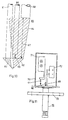
- FIG. 10 shows the part of the photometer to be inserted into the medium to be analyzed. It consists of the light guide 61, which transmits the input light directly to a prism 62. That passed on to prism 62 Light propagates in the prism in the form of the truncated cone 63 (narrow hatching); it leaves the prism in the form of cone 64 (wide hatching). A part of the reflected light is received by the light guide 66 (first partial beam) after passing through a short absorption path 65. Another part of the reflected light is received by the light guide 68 after passing through the longer absorption path 67 (second partial beam).
- the lengths of the absorption sections are variable; they are adapted to the respective measuring tasks.
- a high measuring sensitivity is achieved in that the diameter of the light guide 68 is chosen larger than the diameter of the light guide 66.
- the unit 69 shown in FIG. 10 represents a sensor which is suitable for in-line measurement. As can be seen in FIG. 11, it can be structurally combined with a housing 70, in which a radiation source 71 is arranged, and a receiving device 72 for the signals which are fed through the light guides 66 and 68. With the help of the flange 73, the photometer is connected to the container through which a medium to be analyzed flows. An arrangement can be selected as the radiation source 71, as shown in FIG. 6.
- Rigid light guide rods can be used as light guides 61, 66 and 68.
- the light guides 61, 66 and 68 can also be produced from fiber bundles. It is also possible to make the lower part of the light guide rigid and the upper part as a fiber bundle.
- a cuvette is placed in the second partial beam, i.e. H. pushed into the partial beam that runs through the longer absorption section.
- the receiving device 72 can be designed so that it can receive this calibration cell.
- the receiving device can be equipped with a temperature correction element which takes into account the fact that the photometer is used in media of different temperatures.
Landscapes
- Physics & Mathematics (AREA)
- Spectroscopy & Molecular Physics (AREA)
- Health & Medical Sciences (AREA)
- Life Sciences & Earth Sciences (AREA)
- Chemical & Material Sciences (AREA)
- Analytical Chemistry (AREA)
- Biochemistry (AREA)
- General Health & Medical Sciences (AREA)
- General Physics & Mathematics (AREA)
- Immunology (AREA)
- Pathology (AREA)
- Investigating Or Analysing Materials By Optical Means (AREA)
Claims (10)
Applications Claiming Priority (8)
| Application Number | Priority Date | Filing Date | Title |
|---|---|---|---|
| DE19833339950 DE3339950A1 (de) | 1983-11-04 | 1983-11-04 | Fotometer zur kontinuierlichen analyse eines mediums (gas oder fluessigkeit) |
| DE3339950 | 1983-11-04 | ||
| DE3422309 | 1984-06-15 | ||
| DE19843422309 DE3422309A1 (de) | 1983-11-04 | 1984-06-15 | Fotometer zur kontinuierlichen analyse eines mediums |
| DE19843423471 DE3423471A1 (de) | 1984-06-15 | 1984-06-26 | Fotometer zur kontinuierlichen analyse eines aus mehreren komponenten bestehenden mediums (gas oder fluessigkeit) |
| DE3423471 | 1984-06-26 | ||
| DE19843423922 DE3423922A1 (de) | 1984-06-29 | 1984-06-29 | Fotometer zur kontinuierlichen analyse mehrerer komponenten eines fluessigen oder gasfoermigen mediums |
| DE3423922 | 1984-06-29 |
Publications (3)
| Publication Number | Publication Date |
|---|---|
| EP0145877A2 EP0145877A2 (fr) | 1985-06-26 |
| EP0145877A3 EP0145877A3 (en) | 1986-01-08 |
| EP0145877B1 true EP0145877B1 (fr) | 1989-08-02 |
Family
ID=27433016
Family Applications (1)
| Application Number | Title | Priority Date | Filing Date |
|---|---|---|---|
| EP84112134A Expired EP0145877B1 (fr) | 1983-11-04 | 1984-10-10 | Photomètre pour l'analyse en continu d'un milieu (gaz ou liquide) |
Country Status (2)
| Country | Link |
|---|---|
| EP (1) | EP0145877B1 (fr) |
| DE (1) | DE3479241D1 (fr) |
Families Citing this family (20)
| Publication number | Priority date | Publication date | Assignee | Title |
|---|---|---|---|---|
| US4616134A (en) * | 1984-07-17 | 1986-10-07 | Chevron Research Company | High resolution geologic sample scanning apparatus and process of scanning geologic samples |
| DE3625490A1 (de) * | 1986-07-28 | 1988-02-04 | Kernforschungsz Karlsruhe | Multikomponenten-prozessanalysensystem |
| US4786171A (en) * | 1986-07-29 | 1988-11-22 | Guided Wave, Inc. | Spectral analysis apparatus and method |
| DE3938142A1 (de) * | 1989-11-16 | 1991-05-29 | Mak Maschinenbau Krupp | Verfahren und vorrichtung zur qualitativen und quantitativen bestimmung von inhaltsstoffen |
| US5125747A (en) * | 1990-10-12 | 1992-06-30 | Tytronics, Inc. | Optical analytical instrument and method having improved calibration |
| GB9100502D0 (en) * | 1991-01-10 | 1991-02-20 | Ici Plc | Monitoring device |
| JP2520212B2 (ja) * | 1992-09-07 | 1996-07-31 | 倉敷紡績株式会社 | 濃度測定装置 |
| SE9403543D0 (sv) * | 1994-10-18 | 1994-10-18 | Arums Ltd | Method and probe for on-line optical analysis |
| US5770156A (en) * | 1996-06-04 | 1998-06-23 | In Usa, Inc. | Gas detection and measurement system |
| US5859430A (en) * | 1997-04-10 | 1999-01-12 | Schlumberger Technology Corporation | Method and apparatus for the downhole compositional analysis of formation gases |
| FR2763129B1 (fr) * | 1997-05-06 | 1999-07-02 | Bertin & Cie | Dispositif a fibres optiques de detection automatique de substances etrangeres dans un liquide |
| GB2342610B (en) | 1998-10-14 | 2003-01-15 | Heckett Multiserv Plc | Surface treatment of metal articles |
| US6342948B1 (en) | 1998-11-20 | 2002-01-29 | Waters Investments Limited | Dual pathlength system for light absorbance detection |
| DE10351160B3 (de) * | 2003-11-03 | 2005-03-31 | Roche Diagnostics Gmbh | Durchfluß-Meßküvette und Transmissionsspektrometer zur Untersuchung biologischer Flüssigkeiten |
| RU2396546C2 (ru) * | 2004-12-02 | 2010-08-10 | ФОСС Аналитикал А/С | Спектрофотометр |
| DE102006004916B3 (de) * | 2006-02-01 | 2007-06-14 | GEA Process Engineering (NPS) Ltd., Eastleigh | Vorrichtung zur optischen Messung von Stoffkonzentrationen |
| DE102007058611A1 (de) * | 2007-12-04 | 2009-06-10 | Endress + Hauser Conducta Gesellschaft für Mess- und Regeltechnik mbH + Co. KG | ATR-Sonde |
| DE102008064173B4 (de) * | 2008-12-22 | 2011-06-01 | Universität Rostock | Verfahren und Vorrichtung zur Bestimmung der Stoffkonzentration in gasförmigen oder fluiden Medien mittels optischer Absorptionsspektroskopie mit Breitbandlichtquellen |
| DE102013101523A1 (de) * | 2013-02-15 | 2014-08-21 | B. Braun Avitum Ag | Fotometrische Messvorrichtung und Verfahren zum Messen einer optischen Absorbanz eines Fluids mit einer variablen Konzentration von mindestens einer Licht absorbierenden Substanz, sowie Blutbehandlungsvorrichtung mit einer derartigen Messvorrichtung |
| DE102016008826B4 (de) * | 2016-07-19 | 2024-04-25 | Sartorius Stedim Biotech Gmbh | Spektroskopische Messung für Behälter |
Family Cites Families (2)
| Publication number | Priority date | Publication date | Assignee | Title |
|---|---|---|---|---|
| DE2521934C3 (de) * | 1975-05-16 | 1978-11-02 | Erwin Sick Gmbh Optik-Elektronik, 7808 Waldkirch | Vorrichtung zur Bestimmung der Konzentrationen von Komponenten eines Abgasgemisches |
| JPS56153242A (en) * | 1980-04-30 | 1981-11-27 | Fuji Electric Co Ltd | Measuring device for organic pollution component contained in water |
-
1984
- 1984-10-10 DE DE8484112134T patent/DE3479241D1/de not_active Expired
- 1984-10-10 EP EP84112134A patent/EP0145877B1/fr not_active Expired
Also Published As
| Publication number | Publication date |
|---|---|
| DE3479241D1 (en) | 1989-09-07 |
| EP0145877A2 (fr) | 1985-06-26 |
| EP0145877A3 (en) | 1986-01-08 |
Similar Documents
| Publication | Publication Date | Title |
|---|---|---|
| EP0145877B1 (fr) | Photomètre pour l'analyse en continu d'un milieu (gaz ou liquide) | |
| DE2415049C3 (de) | Spektralphotometer zur Messung des Absoptionsvermögens von chromatographisch getrennten Flüssigkeiten | |
| DE3688349T2 (de) | System zur chemischen Fernanalyse. | |
| DE2364069C3 (de) | Spektralphotometer | |
| EP0163847B1 (fr) | Réfractomètre interférométrique | |
| DE60133002T2 (de) | Spektrophotometer mit mehreren weglängen | |
| DE102009025147B3 (de) | Verfahren zum Betrieb eines Spektrometers zur Gasanalyse, sowie Spektrometer selbst | |
| WO1991014157A2 (fr) | Spectrometre acousto-optique a double faisceau accordable | |
| EP3077793B1 (fr) | Dispositif d'analyse (photomètre) à guides de lumière en série | |
| DE2637246B2 (de) | Verfahren und Vorrichtung zur Inspektion von Glasbehältern | |
| DE3724852C2 (de) | Absorptionsphotometer | |
| DE2420060A1 (de) | Spektralphotometrisches verfahren und mehrweg-spektralphotometer zur durchfuehrung desselben | |
| EP0257229A2 (fr) | Photomètre | |
| DE2651086C3 (fr) | ||
| DE3938142C2 (fr) | ||
| EP1064543B1 (fr) | Appareil de chromatographie en couche mince | |
| DE2927156A1 (de) | Vorrichtung zum messen der sauerstoffkonzentration | |
| EP0087077A2 (fr) | Dispositif pour la mesure optique de gaz | |
| DE2948590A1 (de) | Verfahren und vorrichtung zur gasanalyse | |
| DE3339950A1 (de) | Fotometer zur kontinuierlichen analyse eines mediums (gas oder fluessigkeit) | |
| DE1472144A1 (de) | Spektralphotometer | |
| DE3208737A1 (de) | Optisches mehrstrahl-gasmessgeraet | |
| EP0043522B1 (fr) | Réfractomètre | |
| DE19543729B4 (de) | Spektrometer | |
| DE102006018287B4 (de) | Vorrichtung und Verfahren zur spektralanalytischen Bewertung von Materialien oder Objekten in einem Material- oder Objektstrom |
Legal Events
| Date | Code | Title | Description |
|---|---|---|---|
| PUAI | Public reference made under article 153(3) epc to a published international application that has entered the european phase |
Free format text: ORIGINAL CODE: 0009012 |
|
| AK | Designated contracting states |
Designated state(s): CH DE FR GB LI NL |
|
| RTI1 | Title (correction) | ||
| PUAL | Search report despatched |
Free format text: ORIGINAL CODE: 0009013 |
|
| AK | Designated contracting states |
Designated state(s): CH DE FR GB LI NL |
|
| 17P | Request for examination filed |
Effective date: 19860514 |
|
| 17Q | First examination report despatched |
Effective date: 19870817 |
|
| GRAA | (expected) grant |
Free format text: ORIGINAL CODE: 0009210 |
|
| AK | Designated contracting states |
Kind code of ref document: B1 Designated state(s): CH DE FR GB LI NL |
|
| REF | Corresponds to: |
Ref document number: 3479241 Country of ref document: DE Date of ref document: 19890907 |
|
| ET | Fr: translation filed | ||
| ET1 | Fr: translation filed ** revision of the translation of the patent or the claims | ||
| GBT | Gb: translation of ep patent filed (gb section 77(6)(a)/1977) | ||
| R20 | Corrections of a patent specification |
Effective date: 19890904 |
|
| ET1 | Fr: translation filed ** revision of the translation of the patent or the claims | ||
| PLBE | No opposition filed within time limit |
Free format text: ORIGINAL CODE: 0009261 |
|
| STAA | Information on the status of an ep patent application or granted ep patent |
Free format text: STATUS: NO OPPOSITION FILED WITHIN TIME LIMIT |
|
| 26N | No opposition filed | ||
| PGFP | Annual fee paid to national office [announced via postgrant information from national office to epo] |
Ref country code: DE Payment date: 19910910 Year of fee payment: 8 |
|
| PGFP | Annual fee paid to national office [announced via postgrant information from national office to epo] |
Ref country code: CH Payment date: 19910912 Year of fee payment: 8 |
|
| PGFP | Annual fee paid to national office [announced via postgrant information from national office to epo] |
Ref country code: GB Payment date: 19911002 Year of fee payment: 8 |
|
| PGFP | Annual fee paid to national office [announced via postgrant information from national office to epo] |
Ref country code: FR Payment date: 19911030 Year of fee payment: 8 |
|
| PGFP | Annual fee paid to national office [announced via postgrant information from national office to epo] |
Ref country code: NL Payment date: 19911031 Year of fee payment: 8 |
|
| PG25 | Lapsed in a contracting state [announced via postgrant information from national office to epo] |
Ref country code: GB Effective date: 19921010 |
|
| PG25 | Lapsed in a contracting state [announced via postgrant information from national office to epo] |
Ref country code: LI Effective date: 19921031 Ref country code: CH Effective date: 19921031 |
|
| PG25 | Lapsed in a contracting state [announced via postgrant information from national office to epo] |
Ref country code: NL Effective date: 19930501 |
|
| GBPC | Gb: european patent ceased through non-payment of renewal fee |
Effective date: 19921010 |
|
| NLV4 | Nl: lapsed or anulled due to non-payment of the annual fee | ||
| PG25 | Lapsed in a contracting state [announced via postgrant information from national office to epo] |
Ref country code: FR Effective date: 19930630 |
|
| REG | Reference to a national code |
Ref country code: CH Ref legal event code: PL |
|
| PG25 | Lapsed in a contracting state [announced via postgrant information from national office to epo] |
Ref country code: DE Effective date: 19930701 |
|
| REG | Reference to a national code |
Ref country code: FR Ref legal event code: ST |