EP0145903B1 - Machine électrique rotative - Google Patents
Machine électrique rotative Download PDFInfo
- Publication number
- EP0145903B1 EP0145903B1 EP84112889A EP84112889A EP0145903B1 EP 0145903 B1 EP0145903 B1 EP 0145903B1 EP 84112889 A EP84112889 A EP 84112889A EP 84112889 A EP84112889 A EP 84112889A EP 0145903 B1 EP0145903 B1 EP 0145903B1
- Authority
- EP
- European Patent Office
- Prior art keywords
- rotor
- cooling
- stator
- space
- cooling medium
- Prior art date
- Legal status (The legal status is an assumption and is not a legal conclusion. Google has not performed a legal analysis and makes no representation as to the accuracy of the status listed.)
- Expired
Links
Images
Classifications
-
- H—ELECTRICITY
- H02—GENERATION; CONVERSION OR DISTRIBUTION OF ELECTRIC POWER
- H02K—DYNAMO-ELECTRIC MACHINES
- H02K9/00—Arrangements for cooling or ventilating
- H02K9/02—Arrangements for cooling or ventilating by ambient air flowing through the machine
Definitions
- the invention relates to a rotating electrical machine according to the preamble of claim 1.
- the performance of an electrical machine is limited by the heat loss that occurs during energy conversion and the temperature resistance of the materials used.
- the heat flow must be so intensive by choosing the appropriate cooling system that the permissible limit temperatures are maintained. Starting from the coolant guide, the jacket cooling, the back cooling, the axial and radial internal cooling, the circulation cooling, and the heat dissipation with heat pipes are known.
- a rotating electrical machine according to the preamble of claim 1 has become known from US-A-1 684 168. Thereafter, in the known device, the rotor has axial cooling channels, while separately sucked cooling air flows through the stator windings. So that the brush chamber is not contaminated by oil or other impurities, it is shielded from the air flow to the cooling channels of the rotor and provided with a maintenance opening for access to the brush chamber.
- the known device is not suitable for air routing with a higher degree of protection, in particular with air containing dust or drops, since not all essential current-carrying machine parts are separated from the cooling medium.
- the cooling of the stator pack is insufficient due to the mere flow around the stator windings.
- the cooling systems of the known electrical machines therefore have the disadvantage that they are not or only insufficiently suitable for direct air cooling when operating in air containing dust or drops.
- the invention has for its object to provide a rotating electrical machine of high performance with intensive cooling, which makes it possible to use air containing dust or drops, but the operation should be made possible with higher degrees of protection.
- the cooling medium should be guided in such a way that windings, brushes, commutators or collectors and other current-carrying parts of the machine are not caught by the cooling medium.
- the invention is based on the idea that air guidance with a higher degree of protection with air containing dust or drops can no longer take place in that the cooling air is blown through the machine to a greater or lesser extent.
- the cooling air can only reach certain parts of the machine.
- the outer construction of the machine should not be increased by jackets or cooling fins or the like or the volume and weight.
- the cross section of the machine must therefore be selected so that a sufficient number of cooling channels can be arranged in the stator yoke in the vicinity of the stator windings.
- the St Sjoch should not be weakened.
- a square stand offers itself as a solution, in the corner areas of which a sufficient number of cooling channels can be attached. The invention therefore enables cooling close to the point of origin without the operation and the weight and volume of the machine being impaired.
- connection housing to the stand package can also be formed with air ducts only in the corners.
- the area in the bearing plate around the brush chamber and possibly also in the opposite bearing plate is therefore completely separated from the cooling air of the stator and the rotor. Appropriate covers still ensure free access to the brushes.
- the essence of the invention is therefore to propose a rotating electrical machine in which the cooling air is brought as close as possible to the heat sources, but does not reach any live machine parts that can be impaired in dusty or dripping air, and that the brush space for maintenance is nonetheless is accessible.
- the invention also has the advantage that a targeted and separate from the brush room air supply to the through the separate feed channel Cooling channels of the rotor and the stator can take place, this feed channel being sealed off from the brush chamber by means of a seal which, according to claim 2, can be a gap seal.
- the brush chamber has a separate inlet filter or a separator which filters the inlet air to this chamber. This can keep air pollution away from the brush room.
- the cooling air has a certain overpressure in the space which encloses the current-carrying parts, so that a pressure drop to the outside arises in the area of the seals.
- This is done according to the invention in that a small amount of the cooling air is pressed into this space via a filter or a separator in the area of the supply duct, where the pressure is somewhat higher, and a slight excess pressure is created.
- the seals between the fixed feed channel to the rotor and the rotating rotor can be sealed by this overpressure in the interior.
- the sealing parts between the rotor shaft and the ventilation housing parts consist of casting compound. Compared to parts made of solid material, which are attached to the stand and rotor, this results in a lower expenditure in production.
- the side opposite the brush chamber can also be designed like this. It then carries a wall in the stand part perpendicular to the rotor axis, with a seal between the partition and the rotor.
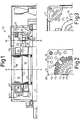
- the DC machine 10 shown in FIG. 1 is shown as a half longitudinal section with a center line 11.
- the DC machine 10 consists of a rectangular stator package 12 with the windings for main poles 13, reversing poles 14 and slots for compensation windings 15 which are known per se.
- the rotor 16 with the rotor winding 17 known per se is located inside the stator stack 12.
- the rectangular stand package 12 has in its corner region 18 longitudinal channels 19 which are used to cool the stand package.
- the yoke 20 is not weakened. A sufficiently large cooling surface can therefore be attached in the vicinity of the windings.
- Corresponding longitudinal channels 21 are provided in the rotor 16 for cooling the rotor.
- connection area of the cooling channels from the stator or rotor package to the adjoining housing parts is adapted.
- the front connection housing part 22, the section B-B of which is shown in FIG. 3 is provided with corresponding supply channels 23 which carry cooling fins 46 in the closed part for cooling the air.
- the cooling channels 19 of the stator core open into the bores of the feed channel 23 in the housing part of the connection housing 22.
- This excess pressure in the space 25 causes the air supply duct 28 to be sealed by an air flow via the gap seal 33.
- the air supply channel 28 opens into the bores 21 of the rotor 16 with a commutator 36. This ensures that no unfiltered air can reach the rotor in the area of the brushes and windings.
- connection housing part 37 at the other end of the stator 12 or rotor 16 has a corresponding winding space 38, which must be cooled.
- the ventilation ducts 19, 21 of the stator core 12 and the rotor 16 open into its surrounding space.
- a further gap seal 39 is provided for sealing to the outside, which is made from a casting compound.
- fan blades 40 are provided, which are cast onto the rotor, and cooling fins 34 on the winding heads 35 of the stator.
- the air flow in the direct current machine proceeds as follows: the ambient air is introduced via the openings 42, on the one hand, into the air supply duct 23 of the connection housing part 22 and from there into the ventilation ducts 19 of the stator assembly, and on the other hand via the air supply duct 28 to the corresponding bores 21 of the rotor 16.
- the ambient air is introduced via the openings 42, on the one hand, into the air supply duct 23 of the connection housing part 22 and from there into the ventilation ducts 19 of the stator assembly, and on the other hand via the air supply duct 28 to the corresponding bores 21 of the rotor 16.
- a very small part of the ambient air is fed through a filter 31 to the room 25 with brushes and windings.
- This air is then introduced into the air supply duct 28 via the gap seal 33 returned, or via the gap 43 between the stator pack 12 and rotor 16 to the gap seal 39 and from there into the housing space of the connection housing part 37. This measure prevents unfiltered ambient air from entering this space, which contains
- the cooling air passes through the cooling ducts 19 and 21 into the rear connection housing part 37 and is conveyed outwards there by the fan blades 40 by means of further ventilation (arrow 44).
Landscapes
- Engineering & Computer Science (AREA)
- Power Engineering (AREA)
- Motor Or Generator Cooling System (AREA)
Claims (6)
Applications Claiming Priority (2)
| Application Number | Priority Date | Filing Date | Title |
|---|---|---|---|
| DE3339094 | 1983-10-28 | ||
| DE19833339094 DE3339094A1 (de) | 1983-10-28 | 1983-10-28 | Rotierende elektrische maschine |
Publications (2)
| Publication Number | Publication Date |
|---|---|
| EP0145903A1 EP0145903A1 (fr) | 1985-06-26 |
| EP0145903B1 true EP0145903B1 (fr) | 1988-02-24 |
Family
ID=6212926
Family Applications (1)
| Application Number | Title | Priority Date | Filing Date |
|---|---|---|---|
| EP84112889A Expired EP0145903B1 (fr) | 1983-10-28 | 1984-10-25 | Machine électrique rotative |
Country Status (2)
| Country | Link |
|---|---|
| EP (1) | EP0145903B1 (fr) |
| DE (2) | DE3339094A1 (fr) |
Cited By (1)
| Publication number | Priority date | Publication date | Assignee | Title |
|---|---|---|---|---|
| WO2019197026A1 (fr) | 2018-04-11 | 2019-10-17 | Pierburg Gmbh | Optimisation de la géométrie du moteur électrique et de la géométrie du carter de moteur électrique d'un compresseur électrique de climatisation, permettant de réduire l'encombrement du moteur |
Families Citing this family (3)
| Publication number | Priority date | Publication date | Assignee | Title |
|---|---|---|---|---|
| CZ71694A3 (en) * | 1992-03-28 | 1994-11-16 | Vem Antriebstech Gmbh | Laminated stator core of case-free three-phase machines |
| DE19716758C2 (de) * | 1997-04-12 | 2002-01-10 | System Antriebstechnik Dresden | Gehäuselose elektrische Maschine mit mehreren unmittelbar fluiddurchströmten axialen Kühlkanälen |
| AT510358B1 (de) * | 2010-09-10 | 2015-07-15 | Traktionssysteme Austria Gmbh | Permanentmagneterregte elektrische maschine |
Citations (1)
| Publication number | Priority date | Publication date | Assignee | Title |
|---|---|---|---|---|
| EP0084271A1 (fr) * | 1982-01-08 | 1983-07-27 | Fanuc Ltd. | Unité de broche |
Family Cites Families (15)
| Publication number | Priority date | Publication date | Assignee | Title |
|---|---|---|---|---|
| DE287118C (fr) * | ||||
| DD57638A (fr) * | ||||
| DE670313C (de) * | 1939-01-16 | Schorch Werke Akt Ges | Explosionssichere elektrische Kollektormaschine | |
| FR519550A (fr) * | 1919-09-19 | 1921-06-11 | Georges Dromel | Ventilation et refroidissement rationnel des machines à courant alternatif |
| US1684168A (en) * | 1926-04-12 | 1928-09-11 | Westinghouse Electric & Mfg Co | Rotary oiler and ventilation |
| DE518773C (de) * | 1929-03-12 | 1931-02-19 | Siemens Schuckertwerke Akt Ges | Foerderrolle, insbesondere fuer Walzwerksrollgaenge |
| BE364674A (fr) * | 1929-10-19 | 1929-11-30 | ||
| DE933939C (de) * | 1939-02-18 | 1955-10-06 | Siemens Ag | Lueftungsanordnung fuer fremdbelueftete elektrische Maschinen mit axialer Luftfuehrung |
| CH234215A (de) * | 1942-01-15 | 1944-09-15 | Hermes Patentverwertungs Gmbh | Ständerblechpaket für durchzugsbelüftete elektrische Maschinen. |
| FR1106080A (fr) * | 1954-06-11 | 1955-12-12 | Inst Rade Koncar | Stator de machines électriques |
| US2873393A (en) * | 1957-03-28 | 1959-02-10 | Westinghouse Electric Corp | Dual-ventilation hydrogen-cooled generators |
| FR1250660A (fr) * | 1959-12-04 | 1961-01-13 | Materiel Electrique S W Le | Perfectionnements aux moteurs électriques à ventilation interne |
| US3413499A (en) * | 1966-06-20 | 1968-11-26 | Gen Electric | Generator air gap entrance baffle for cooling stator core end portions |
| DE1638305A1 (de) * | 1968-01-18 | 1971-07-15 | Vyzk A Vyv Ustav Elek Ckych St | Elektrische rotierende Maschine mit einem Kommutator |
| DE7519067U (de) * | 1974-06-26 | 1975-10-16 | Asea | Elektrischer Motor |
-
1983
- 1983-10-28 DE DE19833339094 patent/DE3339094A1/de not_active Withdrawn
-
1984
- 1984-10-25 EP EP84112889A patent/EP0145903B1/fr not_active Expired
- 1984-10-25 DE DE8484112889T patent/DE3469473D1/de not_active Expired
Patent Citations (1)
| Publication number | Priority date | Publication date | Assignee | Title |
|---|---|---|---|---|
| EP0084271A1 (fr) * | 1982-01-08 | 1983-07-27 | Fanuc Ltd. | Unité de broche |
Cited By (1)
| Publication number | Priority date | Publication date | Assignee | Title |
|---|---|---|---|---|
| WO2019197026A1 (fr) | 2018-04-11 | 2019-10-17 | Pierburg Gmbh | Optimisation de la géométrie du moteur électrique et de la géométrie du carter de moteur électrique d'un compresseur électrique de climatisation, permettant de réduire l'encombrement du moteur |
Also Published As
| Publication number | Publication date |
|---|---|
| EP0145903A1 (fr) | 1985-06-26 |
| DE3339094A1 (de) | 1985-05-09 |
| DE3469473D1 (en) | 1988-03-31 |
Similar Documents
| Publication | Publication Date | Title |
|---|---|---|
| DE4038663C2 (de) | Wechselstrom-Lichtmaschine für Fahrzeuge | |
| DE102008022105B4 (de) | Flüssigkeitsgekühlte elektrische Maschine sowie Verfahren zur Kühlung einer solchen elektrischen Maschine | |
| DE4229395C2 (de) | Oberflächengekühlte, geschlossene elektrische Maschine | |
| DE19635196A1 (de) | Kühlanordnung für einen Elektromotor | |
| DE4443427C2 (de) | Elektrische Maschine | |
| DE112013003975T5 (de) | Flüssigkeitsgekühlter Elektromotor | |
| EP1614205A2 (fr) | Machine electrique a empilages de toles et bobines de stator et de rotor refroidis | |
| DE2827364A1 (de) | Gleitring-dichtung | |
| DE9408559U1 (de) | Elektrische Maschine mit einem innengekühlten Läufer | |
| EP0589187B1 (fr) | Machine électrique entièrement fermeé, refroidie en surface par liquide | |
| DE10335141B4 (de) | Elektrische Maschine mit Kühlmittelführungskanal | |
| DE1538817B2 (de) | Kuehlsystem fuer dynamoelektrische maschinen | |
| DE102020206000A1 (de) | Elektrische Maschine mit Bypass-Kühlkanal | |
| DE19716758C2 (de) | Gehäuselose elektrische Maschine mit mehreren unmittelbar fluiddurchströmten axialen Kühlkanälen | |
| EP0585644A1 (fr) | Machine électrique entièrement fermée, refroidie en surface par liquide | |
| EP0145903A1 (fr) | Machine électrique rotative | |
| DE1033322B (de) | Gaskuehlsystem fuer dynamoelektrische Maschinen | |
| DE29714740U1 (de) | Elektrische Maschine | |
| DE2506184C3 (de) | Durchzugsbelüftete Gleichstrommaschine | |
| DE10228224B3 (de) | Vorrichtung zur Kühlung einer Stromerzeugereinheit | |
| DE19913199A1 (de) | Verfahren und Vorrichtung zur Kühlung einer elektrischen Maschine mit einem Stator und einem Rotor | |
| DE19608286B4 (de) | Belüftungssystem für den Ringmotor einer Rohrmühle | |
| EP0074514A1 (fr) | Arrangement d'un dispositif de refroidissement et d'un moteur avec un ventilateur fixé sur son arbre, notamment pour une installation à compresseur à vis | |
| DE2739631C3 (de) | Schlagwettergeschützter, druckfest gekapselter Trockentransformator | |
| DE1922765B2 (de) | Fluessigkeitsgekuehlter rotor einer dynamoelektrischen maschine |
Legal Events
| Date | Code | Title | Description |
|---|---|---|---|
| PUAI | Public reference made under article 153(3) epc to a published international application that has entered the european phase |
Free format text: ORIGINAL CODE: 0009012 |
|
| AK | Designated contracting states |
Designated state(s): CH DE FR GB IT LI |
|
| 17P | Request for examination filed |
Effective date: 19851219 |
|
| 17Q | First examination report despatched |
Effective date: 19861113 |
|
| GRAA | (expected) grant |
Free format text: ORIGINAL CODE: 0009210 |
|
| AK | Designated contracting states |
Kind code of ref document: B1 Designated state(s): CH DE FR GB IT LI |
|
| GBT | Gb: translation of ep patent filed (gb section 77(6)(a)/1977) | ||
| REF | Corresponds to: |
Ref document number: 3469473 Country of ref document: DE Date of ref document: 19880331 |
|
| ET | Fr: translation filed | ||
| ITF | It: translation for a ep patent filed | ||
| PGFP | Annual fee paid to national office [announced via postgrant information from national office to epo] |
Ref country code: DE Payment date: 19881015 Year of fee payment: 5 |
|
| PLBE | No opposition filed within time limit |
Free format text: ORIGINAL CODE: 0009261 |
|
| STAA | Information on the status of an ep patent application or granted ep patent |
Free format text: STATUS: NO OPPOSITION FILED WITHIN TIME LIMIT |
|
| PGFP | Annual fee paid to national office [announced via postgrant information from national office to epo] |
Ref country code: FR Payment date: 19890111 Year of fee payment: 5 |
|
| 26N | No opposition filed | ||
| PG25 | Lapsed in a contracting state [announced via postgrant information from national office to epo] |
Ref country code: GB Effective date: 19891025 |
|
| PG25 | Lapsed in a contracting state [announced via postgrant information from national office to epo] |
Ref country code: LI Effective date: 19891031 Ref country code: CH Effective date: 19891031 |
|
| GBPC | Gb: european patent ceased through non-payment of renewal fee | ||
| PG25 | Lapsed in a contracting state [announced via postgrant information from national office to epo] |
Ref country code: FR Effective date: 19900629 |
|
| REG | Reference to a national code |
Ref country code: CH Ref legal event code: PL |
|
| PG25 | Lapsed in a contracting state [announced via postgrant information from national office to epo] |
Ref country code: DE Effective date: 19900703 |
|
| REG | Reference to a national code |
Ref country code: FR Ref legal event code: ST |