EP0145921B1 - Elektro-pneumatische Steuerung für eine Druckmittelbremsanlage - Google Patents
Elektro-pneumatische Steuerung für eine Druckmittelbremsanlage Download PDFInfo
- Publication number
- EP0145921B1 EP0145921B1 EP84113270A EP84113270A EP0145921B1 EP 0145921 B1 EP0145921 B1 EP 0145921B1 EP 84113270 A EP84113270 A EP 84113270A EP 84113270 A EP84113270 A EP 84113270A EP 0145921 B1 EP0145921 B1 EP 0145921B1
- Authority
- EP
- European Patent Office
- Prior art keywords
- switch means
- pressure
- electrically actuated
- fluid pressure
- electro
- Prior art date
- Legal status (The legal status is an assumption and is not a legal conclusion. Google has not performed a legal analysis and makes no representation as to the accuracy of the status listed.)
- Expired
Links
- 239000012530 fluid Substances 0.000 title claims description 39
- 230000000694 effects Effects 0.000 description 2
- 230000000994 depressogenic effect Effects 0.000 description 1
- 230000009977 dual effect Effects 0.000 description 1
- 230000007257 malfunction Effects 0.000 description 1
- 238000011144 upstream manufacturing Methods 0.000 description 1
- 238000013022 venting Methods 0.000 description 1
Images
Classifications
-
- B—PERFORMING OPERATIONS; TRANSPORTING
- B60—VEHICLES IN GENERAL
- B60T—VEHICLE BRAKE CONTROL SYSTEMS OR PARTS THEREOF; BRAKE CONTROL SYSTEMS OR PARTS THEREOF, IN GENERAL; ARRANGEMENT OF BRAKING ELEMENTS ON VEHICLES IN GENERAL; PORTABLE DEVICES FOR PREVENTING UNWANTED MOVEMENT OF VEHICLES; VEHICLE MODIFICATIONS TO FACILITATE COOLING OF BRAKES
- B60T13/00—Transmitting braking action from initiating means to ultimate brake actuator with power assistance or drive; Brake systems incorporating such transmitting means, e.g. air-pressure brake systems
- B60T13/10—Transmitting braking action from initiating means to ultimate brake actuator with power assistance or drive; Brake systems incorporating such transmitting means, e.g. air-pressure brake systems with fluid assistance, drive, or release
- B60T13/66—Electrical control in fluid-pressure brake systems
- B60T13/68—Electrical control in fluid-pressure brake systems by electrically-controlled valves
- B60T13/683—Electrical control in fluid-pressure brake systems by electrically-controlled valves in pneumatic systems or parts thereof
Definitions
- This invention relates to an electro-pneumatic control for a vehicle fluid pressure braking system.
- the system disclosed in this reference does not include pressure responsive sensors to automatically permit the system to communicate full braking pressure to the vehicle parking brake system, and also does not require that the system be completely re-set in case of a loss of pressure that results in the application of the vehicle spring or parking brake.
- the system of the present invention has the advantage of eliminating all pressure connections within the cab of the vehicle on which the system is mounted, as the pneumatic connections formerly necessary are replaced with electro mechanical switches.
- the system according to the present invention also has the advantage of permitting pressure in the vehicle parking brake system to build up to full system pressure after the switches are operated to communicate a predetermined minimum pressure level to the vehicle parking brake system.
- the system also has the advantage of requiring that the system be completely re-set in the event that the parking or spring brake is automatically applied due to a loss of system pressure. Accordingly, the present system requires that system pressure be returned to normal after a system pressure loss so that the parking brakes may be released in the normal manner.
- the present invention comprises an electro-pneumatic control for a fluid pressure braking system having a source of fluid pressure and a fluid pressure device, said electro-pneumatic control comprising electrically actuated valve means controlling communication to said fluid pressure device from said fluid pressure source, switch means for controlling said electrically actuated valve means, said switch means including a pressure-responsive switching device responsive to the fluid pressure level at said fluid pressure device for maintaining actuation of said electrically actuated valve means as long as the pressure level at said fluid pressure device is above a predetermined level after the pressure level at said fluid pressure device initially attains said predetermined level (see US-A-4 339 134) characterized in that said switch means includes manually actuated switch means for actuating the electrically actuated valve means, said pressure-responsive switching device maintaining actuation of the electrically actuated valve means to permit release of said manually actuated switch means while maintaining communication to the fluid pressure device when the pressure level sensed by the pressure-responsive switching means attains the predetermined level.
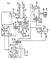
- an electro-pneumatic control system for a vehicle fluid pressure braking system is generally indicated by the numeral 10 for the tractor portion of a tractor- trailer combination vehicle.
- the system 10 includes a conventional tractor protection valve generally indicated by the numeral 12.
- the tractor protection valve 12 includes an outlet port 14 which is communicated with a trailer control line 16.
- the trailer control line 16 terminates in a gladhand connector 18 of conventional design, which is adapted to be connected to a corresponding line on the trailer so that a service brake actuation signal may be communicated through the control line 16 to actuate the service brakes on the trailer.
- the tractor protection valve 12 further includes a pair of inlet ports 20, 22 which are connected, via fluid lines 24, 26 respectively, to the corresponding outlet ports (not shown) of a conventional, treadle-operated dual brake valve which, is mounted in the vehicle cab for operation by the vehicle operator when a service brake application is to be effected.
- the tractor protection valve 12 includes mechanism (not shown) for selecting the higher of the fluid pressure levels at the ports 20, 22 for communication through the outlet port 14 to the trailer control line 16.
- Tractor protection valve 12 further includes another outlet port 28 which is communicated with a trailer supply line 30.
- Trailer supply line 30 terminates in another gladhand connector 32 which is adopted for connection to a corresponding connector on the trailer so that fluid pressure communicated through the supply line 30 is able to charge reservoirs carried on the trailer.
- Tractor protection valve 12 further includes an inlet port 34 which is connected to a double check valve 36 of conventional design, which communicates the inlet port 34 of the tractor protection valve 12 with the higher of the fluid pressure levels communicated through lines 38, 40.
- the pressure lines 38, 40 are each connected to separated, isolated fluid pressure sources, such as fluid reservoirs, which are charged by, for example, the vehicle automotive air compressor.
- the tractor protection valve communicates the inlet port 34 to the outlet port 28 thereof to effect charging of the aforementioned reservoir carried by the trailer when the trailer supply line 30 is connected to the corresponding supply line on the trailer.
- Electro-pneumatic control system 10 further includes a double pole, single throw, push-through switch generally indicated by the numeral 42.
- the terminal 44 of the switch 42 is connected to a source of electrical energy, such as the vehicle storage battery 46.
- a switch lever or knob 48 may be thrown to connect the terminal 44 with terminal 50.
- the lever or knob 48 can also be “pushed through” to make momentary contact between the terminal 52 and terminal 54, which is common with the terminal 50.
- the terminal 50 is connected to a terminal 56 of a single pole, single throw, push-to-close momentary contact electrical switch 58. As long as the switch operator 60 is depressed by the vehicle operator, the switch 58 completes an electrical circuit between the terminal 56 and the terminal 62 thereof.
- Terminal 50 of switch 42 and terminal 56 of switch 58 are both connected to a terminal 64 of an electrical relay generally indicated by the numeral 66.
- the relay 66 upon energization of the coil 68 thereof, completes an electrical circuit between the terminal 64 and the terminal 70 thereof.
- the coil 68 of the relay 66 is connected through a terminal 72 of the relay 66 to the terminal 62 of the switch 58.
- the terminal 64 of the relay 66 is connected to the terminal 50 of the switch 42 and the terminal 56 of the switch 58.
- Terminal 62 of switch 58 is also connected to a solenoid-controlled valve generally indicated by the numeral 74 which controls communication from the double check valve 36 to the inlet port 34 of the tractor protection valve 12.
- the solenoid valve 74 is normally closed to prevent communication to the inlet port 34 of the tractor protection valve and to vent the inlet port 34 to atmosphere. However, when the solenoid valve 74 is actuated, the vent is closed, and the inlet port 34 is communicated to the outlet of the double check valve 36.
- a pressure-responsive switch generally indicated by the numeral 76 is responsive to the pressure level in the supply line 30 to close an electrical circuit connecting the terminal 70 of the relay 66 with the coil 68 thereof when the pressure level in the supply line 30 exceeds a predetermined level.
- Electro-pneumatic control system 10 further includes a spring-applied, fluid pressure-released parking brake generally indicated by the-numeral 78, which is of conventional design.
- the parking brake 78 is released by hold-off pressure communicated to the inlet port 80 thereof through supply line 86.
- a solenoid valve generally indicated by the numeral 84 is installed in the supply line 86, and normally vents the port 80 to atmosphere, but is responsive to an electrical signal to close the vent and communicate the port 80 with a fluid pressure source (not shown) which is communicated with the upstream portion of the supply line 86.
- a pressure-responsive switch 88 similar to the pressure-responsive switch 76 is also installed in communication with the port 80.
- the pressure-responsive switch 88 is responsive to a predetermined pressure level in the supply line 86 downstream of the solenoid valve 84 to close an electrical circuit between the terminal 90 of an electrical relay generally indicated by the numeral 92 and the coil 94 thereof through a terminal 96.
- the other terminal 98 of the relay 92 is connected to the terminal 50 of the switch 42.
- Terminal 96 of the switch 92 is also connected with the terminal 52 of the switch 42.
- the port 80 of the parking brake 78 is vented through the solenoid valve 84 so that the parking brake 78 is applied.
- the supply line 30 is vented through the solenoid valve 74, and, since the parking brakes on the trailer are controlled by the pressure in supply line 30, the parking brakes on the trailer will also be applied.
- the vehicle operator closes the switch operator 48 to complete the electrical circuit between the terminals 44, 50 of the switch 42, thereby connecting the terminals 64 and 98 of the relays 66 and 92 respectively with the source of electrical energy 46.
- the operator then closes the switch 58 by holding down the switch operator 60 to connect the terminals 56 with the terminals 62 thereof. Accordingly, the coil 68 of the relay 66 is actuated, and the solenoid valve 74 is actuated to communicate double check valve 36 with supply line 30.
- the switch 76 closes and, since actuation of the solenoid 68 has already closed the circuit between terminal 64 and 70 of the electrical relay 66, closure of the pressure-actuated switch 76 completes an electrical circuit between the electrical energy source 46 and the solenoid valve 74 so that the vehicle operator may then release the operator 60 of the switch 58 while the pressure-responsive switch 76 maintains actuation of the solenoid valve 74. Accordingly, pressure in the supply line 30 then automatically increases to full system pressure. Simultaneously, the vehicle operator "pushes through" the operator 48 of the switch 42 to connect the terminal 52 of the switch 42 with the source of electrical energy 46.
- coil 94 of the relay 92 is actuated to complete the electrical circuit between the terminals 98 and 90 thereof. Since the terminal 98 has already been connected to the source of electrical energy 46 due to closure of the circuit between the terminals 44 and 50 of the switch 42, actuation of the coil 94 of relay 92 actuates the solenoid valve 84 to permit communication of the inlet port 80 of the parking brake 78 with the portion 86 of the supply line 82 which is communicated to the fluid pressure source. Accordingly, the pressure level in the parking brake 78 begins to build to release the brake. When the pressure level at the port 80 attains a predetermined level, the pressure-responsive switch 88 closes, thereby completing an electrical circuit between the coil 94 and the terminal 90 of the relay 92.
- the pressure-responsive switch 88 maintains actuation of the solenoid valve 84, permitting release of the switch operator 48, even though the switch operator 48 remains in the position connecting the terminal 44 with the terminal 50. Accordingly, the pressure at the parking brake 78 is permitted to build to full system pressure to maintain release of the parking brake 78.
- switch operator 48 When the vehicle is to be parked, and it is necessary to vent the supply line 30 to apply the trailer parking brakes and to vent the supply line 82 to apply the parking brake 78, switch operator 48 is moved to the position illustrated in the drawing, thereby breaking the connection between the terminals 44 and 50 of the switch 42. This breaks the electrical connection to the source of electrical energy 46 and the terminal 64 on relay 66 and the terminal 98 on relay 92. Power is also removed to the solenoid valves 74 and 84, thereby venting the supply line 30 and the supply line 86. If the fluid pressure braking system on either the tractor or trailer should malfunction, causing a loss of pressure in either the supply line 30 or the supply line 86, the corresponding pressure-responsive switch 76 or 88 opens.
- switch 76 opens, the connection between the solenoid valve 74 and the electrical energy source 46 is broken, thereby causing valve 74 to terminate communication between the double check valve 36 and the inlet port 34 of tractor protection valve 12 and to vent the inlet port 34 of tractor protection valve 12 to atmosphere.
- the switch 58 In order to again charge the supply line 30, the switch 58 must be actuated by the vehicle operator to close the valve 74 until pressure builds in the system sufficient to reopen the switch 76.
- switch 88 opens to break the connection between the solenoid valve 84 and the electrical energy source 46 and also to remove power to the coil 94 so that the relay 92 opens.
- the parking brake 78 will not immediately be recharged in case system pressure returns to normal, but the parking brake 78 will continue to be vented through the solenoid valve 84 until the vehicle operator again closes the push-through contact 52 to build pressure in the system as described hereinabove.
Landscapes
- Engineering & Computer Science (AREA)
- Transportation (AREA)
- Mechanical Engineering (AREA)
- Braking Systems And Boosters (AREA)
- Valves And Accessory Devices For Braking Systems (AREA)
Claims (7)
Applications Claiming Priority (2)
| Application Number | Priority Date | Filing Date | Title |
|---|---|---|---|
| US06/562,321 US4550953A (en) | 1983-12-16 | 1983-12-16 | Electro-pneumatic control for a vehicle fluid pressure braking system |
| US562321 | 1983-12-16 |
Publications (3)
| Publication Number | Publication Date |
|---|---|
| EP0145921A2 EP0145921A2 (de) | 1985-06-26 |
| EP0145921A3 EP0145921A3 (en) | 1985-07-24 |
| EP0145921B1 true EP0145921B1 (de) | 1989-01-18 |
Family
ID=24245811
Family Applications (1)
| Application Number | Title | Priority Date | Filing Date |
|---|---|---|---|
| EP84113270A Expired EP0145921B1 (de) | 1983-12-16 | 1984-11-05 | Elektro-pneumatische Steuerung für eine Druckmittelbremsanlage |
Country Status (8)
| Country | Link |
|---|---|
| US (1) | US4550953A (de) |
| EP (1) | EP0145921B1 (de) |
| JP (1) | JPH0651467B2 (de) |
| AU (1) | AU560915B2 (de) |
| BR (1) | BR8406555A (de) |
| CA (1) | CA1229111A (de) |
| DE (1) | DE3476186D1 (de) |
| ES (1) | ES8507054A1 (de) |
Families Citing this family (16)
| Publication number | Priority date | Publication date | Assignee | Title |
|---|---|---|---|---|
| US4785532A (en) * | 1985-10-22 | 1988-11-22 | Amp Incorporated | Method of making electrical connector assembly for antiskid braking system |
| US4763959A (en) * | 1987-10-23 | 1988-08-16 | Allied-Signal Inc. | Electronic control for fluid pressure braking system |
| US5061015A (en) * | 1990-04-12 | 1991-10-29 | Allied-Signal Inc. | Tractor protection control system |
| US5404301A (en) * | 1993-06-07 | 1995-04-04 | Eaton Corporation | Method and apparatus of vehicle transmission control by assured minimum pulse width |
| US5816371A (en) * | 1996-05-14 | 1998-10-06 | Hayes Industrial Brake, Inc. | Pressure release parking brake actuator |
| US6290309B1 (en) | 1998-12-18 | 2001-09-18 | Meritor Wabco Vehicle Control Systems | Spring brake actuation for electronically controlled brake system |
| US6322159B1 (en) * | 2000-09-22 | 2001-11-27 | Honeywell Commercial Vehicle Systems Co. | Latching electric-control vehicle air brake system |
| US6752472B2 (en) * | 2001-08-23 | 2004-06-22 | Imi Norgren, Inc. | Electric parking brake control |
| US7784879B2 (en) * | 2002-07-16 | 2010-08-31 | Haldex Brake Corporation | Electronic control air management with parking brake and trailer supply control |
| WO2004076254A1 (en) * | 2003-02-24 | 2004-09-10 | Bendix Commercial Vehicle Systems Llc | Electro-pneumatic latching valve system |
| US7337041B2 (en) * | 2004-06-14 | 2008-02-26 | Fisher Controls International | Feedback control methods and apparatus for electro-pneumatic control systems |
| DE102007014427B4 (de) * | 2007-03-22 | 2010-09-09 | Knorr-Bremse Systeme für Nutzfahrzeuge GmbH | Elektrische Feststellbremsanlage für ein Nutzfahrzeug und Betriebsverfahren |
| CN102556061B (zh) * | 2012-01-12 | 2014-09-24 | 安徽铜冠机械股份有限公司 | 一种柴油机熄火与驻车制动联锁控制装置 |
| US9308861B2 (en) | 2014-03-13 | 2016-04-12 | Bendix Commercial Vehicle Systems Llc | Vehicle dash switch module with haptic and visual indication |
| DE102016010460A1 (de) * | 2016-08-31 | 2018-03-01 | Wabco Gmbh | Elektronisch steuerbares pneumatisches Bremssystem in einem Nutzfahrzeug sowie Verfahren zum elektronischen Steuern eines pneumatischen Bremssystems in einem Nutzfahrzeug |
| DE102017006006A1 (de) * | 2017-06-26 | 2018-12-27 | Wabco Gmbh | Verfahren zum Betrieb einer elektropneumatischen Feststellbremsanlage eines Fahrzeugzuges |
Family Cites Families (11)
| Publication number | Priority date | Publication date | Assignee | Title |
|---|---|---|---|---|
| US2678852A (en) * | 1950-01-28 | 1954-05-18 | Westinghouse Air Brake Co | Fluid pressure brake equipment |
| US2937907A (en) * | 1958-11-28 | 1960-05-24 | New York Air Brake Co | Auxiliary quick service venting mechanism |
| US3497268A (en) * | 1968-10-07 | 1970-02-24 | Berg Mfg & Sales Co | Trailer brake fill system |
| US3482885A (en) * | 1968-11-05 | 1969-12-09 | Berg Mfg & Sales Co | Electric-pneumatic brake system |
| US3507543A (en) * | 1968-11-05 | 1970-04-21 | Berg Mfg & Sales Co | Trailer brake release system |
| US3482886A (en) * | 1968-11-05 | 1969-12-09 | Berg Mfg & Sales Co | Trailer brake and release system |
| JPS522523B2 (de) * | 1972-08-02 | 1977-01-22 | ||
| US3819238A (en) * | 1972-12-06 | 1974-06-25 | E Cermak | Brake and emergency brake installation for vehicle trailers |
| DE2420665B2 (de) * | 1974-04-29 | 1976-10-28 | Cermak, Eduard, Dipl.-Ing., 7100 Heilbronn | Elektropneumatische bremssteuereinrichtung fuer fahrzeugzuege |
| US3985210A (en) * | 1975-02-18 | 1976-10-12 | Caterpillar Tractor Co. | Automatically engaged emergency parking brake |
| US4339154A (en) * | 1980-07-03 | 1982-07-13 | Clark Equipment Company | Vehicle brake system |
-
1983
- 1983-12-16 US US06/562,321 patent/US4550953A/en not_active Expired - Lifetime
-
1984
- 1984-11-05 EP EP84113270A patent/EP0145921B1/de not_active Expired
- 1984-11-05 DE DE8484113270T patent/DE3476186D1/de not_active Expired
- 1984-11-07 CA CA000467227A patent/CA1229111A/en not_active Expired
- 1984-11-21 JP JP59246972A patent/JPH0651467B2/ja not_active Expired - Lifetime
- 1984-12-11 AU AU36491/84A patent/AU560915B2/en not_active Ceased
- 1984-12-14 BR BR8406555A patent/BR8406555A/pt not_active IP Right Cessation
- 1984-12-14 ES ES538628A patent/ES8507054A1/es not_active Expired
Also Published As
| Publication number | Publication date |
|---|---|
| US4550953A (en) | 1985-11-05 |
| ES538628A0 (es) | 1985-08-16 |
| ES8507054A1 (es) | 1985-08-16 |
| CA1229111A (en) | 1987-11-10 |
| JPS60135360A (ja) | 1985-07-18 |
| DE3476186D1 (en) | 1989-02-23 |
| EP0145921A2 (de) | 1985-06-26 |
| EP0145921A3 (en) | 1985-07-24 |
| BR8406555A (pt) | 1985-10-15 |
| AU3649184A (en) | 1985-06-20 |
| JPH0651467B2 (ja) | 1994-07-06 |
| AU560915B2 (en) | 1987-04-16 |
Similar Documents
| Publication | Publication Date | Title |
|---|---|---|
| US4550953A (en) | Electro-pneumatic control for a vehicle fluid pressure braking system | |
| US5061015A (en) | Tractor protection control system | |
| CA1291548C (en) | Electronic control for fluid pressure braking system | |
| EP0235377B1 (de) | Druckluftbremsanlage für Zugfahrzeug | |
| US5036961A (en) | Auxiliary parking brake system | |
| AU2004215405B2 (en) | Electro-pneumatic latching valve system | |
| JP2000506804A (ja) | 自動車のエアブレーキ装置のためのトレーラ制御弁を備えたトレーラ制御モジュール | |
| EP0569357B1 (de) | Elektropneumatische federspeicher- und betriebsbremsbetätigungsvorrichtung | |
| EP0469087B1 (de) | Rückfahrsicherungsvorrichtung und verfahren dafür | |
| JPH0659823B2 (ja) | 電気制御される圧力媒体制動装置 | |
| EP0394065A2 (de) | Reservebremsanlage | |
| US4109968A (en) | Tractor-trailer brake system with improved means for assuring application of trailer brakes concomitantly with tractor brakes | |
| US4472001A (en) | Fluid pressure braking system | |
| US5251967A (en) | Fluid pressure braking system with low pressure warning mechanism | |
| US5226692A (en) | Fluid pressure braking system | |
| EP0203313B1 (de) | Druckmittelbremsanlage | |
| AU2001292742A1 (en) | Latching electric-control vehicle air brake system | |
| JPS58185357A (ja) | 弁装置 | |
| GB2173560A (en) | Emergency brake actuating system | |
| EP1550593B1 (de) | Elektronisches Regelungssystem für die Bremsegelung eines Gleisfahrzeugs | |
| JPS6211697B2 (de) | ||
| JPS6224303B2 (de) | ||
| JPS6226939B2 (de) | ||
| GB2098755A (en) | Air compressor systems | |
| MXPA95002162A (en) | Electro-pneumatic control system for puer |
Legal Events
| Date | Code | Title | Description |
|---|---|---|---|
| PUAI | Public reference made under article 153(3) epc to a published international application that has entered the european phase |
Free format text: ORIGINAL CODE: 0009012 |
|
| PUAL | Search report despatched |
Free format text: ORIGINAL CODE: 0009013 |
|
| AK | Designated contracting states |
Designated state(s): DE FR GB IT |
|
| AK | Designated contracting states |
Designated state(s): DE FR GB IT |
|
| 17P | Request for examination filed |
Effective date: 19851218 |
|
| 17Q | First examination report despatched |
Effective date: 19860730 |
|
| D17Q | First examination report despatched (deleted) | ||
| RAP1 | Party data changed (applicant data changed or rights of an application transferred) |
Owner name: ALLIED-SIGNAL INC. |
|
| GRAA | (expected) grant |
Free format text: ORIGINAL CODE: 0009210 |
|
| AK | Designated contracting states |
Kind code of ref document: B1 Designated state(s): DE FR GB IT |
|
| ITF | It: translation for a ep patent filed | ||
| REF | Corresponds to: |
Ref document number: 3476186 Country of ref document: DE Date of ref document: 19890223 |
|
| ET | Fr: translation filed | ||
| PLBE | No opposition filed within time limit |
Free format text: ORIGINAL CODE: 0009261 |
|
| STAA | Information on the status of an ep patent application or granted ep patent |
Free format text: STATUS: NO OPPOSITION FILED WITHIN TIME LIMIT |
|
| 26N | No opposition filed | ||
| ITTA | It: last paid annual fee | ||
| PGFP | Annual fee paid to national office [announced via postgrant information from national office to epo] |
Ref country code: GB Payment date: 20011004 Year of fee payment: 18 |
|
| PGFP | Annual fee paid to national office [announced via postgrant information from national office to epo] |
Ref country code: FR Payment date: 20011105 Year of fee payment: 18 |
|
| PGFP | Annual fee paid to national office [announced via postgrant information from national office to epo] |
Ref country code: DE Payment date: 20011130 Year of fee payment: 18 |
|
| REG | Reference to a national code |
Ref country code: GB Ref legal event code: IF02 |
|
| PG25 | Lapsed in a contracting state [announced via postgrant information from national office to epo] |
Ref country code: GB Free format text: LAPSE BECAUSE OF NON-PAYMENT OF DUE FEES Effective date: 20021105 |
|
| REG | Reference to a national code |
Ref country code: GB Ref legal event code: 732E |
|
| PG25 | Lapsed in a contracting state [announced via postgrant information from national office to epo] |
Ref country code: DE Free format text: LAPSE BECAUSE OF NON-PAYMENT OF DUE FEES Effective date: 20030603 |
|
| GBPC | Gb: european patent ceased through non-payment of renewal fee | ||
| PG25 | Lapsed in a contracting state [announced via postgrant information from national office to epo] |
Ref country code: FR Free format text: LAPSE BECAUSE OF NON-PAYMENT OF DUE FEES Effective date: 20030731 |
|
| REG | Reference to a national code |
Ref country code: FR Ref legal event code: TP Ref country code: FR Ref legal event code: ST |