EP0145952A2 - Scharnierarm mit Befestigungsplatte - Google Patents
Scharnierarm mit Befestigungsplatte Download PDFInfo
- Publication number
- EP0145952A2 EP0145952A2 EP84113657A EP84113657A EP0145952A2 EP 0145952 A2 EP0145952 A2 EP 0145952A2 EP 84113657 A EP84113657 A EP 84113657A EP 84113657 A EP84113657 A EP 84113657A EP 0145952 A2 EP0145952 A2 EP 0145952A2
- Authority
- EP
- European Patent Office
- Prior art keywords
- hinge arm
- lever
- legs
- arm according
- cover plate
- Prior art date
- Legal status (The legal status is an assumption and is not a legal conclusion. Google has not performed a legal analysis and makes no representation as to the accuracy of the status listed.)
- Granted
Links
Images

Classifications
-
- E—FIXED CONSTRUCTIONS
- E05—LOCKS; KEYS; WINDOW OR DOOR FITTINGS; SAFES
- E05D—HINGES OR SUSPENSION DEVICES FOR DOORS, WINDOWS OR WINGS
- E05D7/00—Hinges or pivots of special construction
- E05D7/12—Hinges or pivots of special construction to allow easy detachment of the hinge from the wing or the frame
- E05D7/123—Hinges or pivots of special construction to allow easy detachment of the hinge from the wing or the frame specially adapted for cabinets or furniture
- E05D7/125—Hinges or pivots of special construction to allow easy detachment of the hinge from the wing or the frame specially adapted for cabinets or furniture the hinge having two or more pins
-
- E—FIXED CONSTRUCTIONS
- E05—LOCKS; KEYS; WINDOW OR DOOR FITTINGS; SAFES
- E05D—HINGES OR SUSPENSION DEVICES FOR DOORS, WINDOWS OR WINGS
- E05D5/00—Construction of single parts, e.g. the parts for attachment
- E05D5/02—Parts for attachment, e.g. flaps
- E05D5/0276—Parts for attachment, e.g. flaps for attachment to cabinets or furniture, the hinge having two or more pins
-
- E—FIXED CONSTRUCTIONS
- E05—LOCKS; KEYS; WINDOW OR DOOR FITTINGS; SAFES
- E05Y—INDEXING SCHEME ASSOCIATED WITH SUBCLASSES E05D AND E05F, RELATING TO CONSTRUCTION ELEMENTS, ELECTRIC CONTROL, POWER SUPPLY, POWER SIGNAL OR TRANSMISSION, USER INTERFACES, MOUNTING OR COUPLING, DETAILS, ACCESSORIES, AUXILIARY OPERATIONS NOT OTHERWISE PROVIDED FOR, APPLICATION THEREOF
- E05Y2600/00—Mounting or coupling arrangements for elements provided for in this subclass
- E05Y2600/50—Mounting methods; Positioning
- E05Y2600/52—Toolless
- E05Y2600/53—Snapping
-
- E—FIXED CONSTRUCTIONS
- E05—LOCKS; KEYS; WINDOW OR DOOR FITTINGS; SAFES
- E05Y—INDEXING SCHEME ASSOCIATED WITH SUBCLASSES E05D AND E05F, RELATING TO CONSTRUCTION ELEMENTS, ELECTRIC CONTROL, POWER SUPPLY, POWER SIGNAL OR TRANSMISSION, USER INTERFACES, MOUNTING OR COUPLING, DETAILS, ACCESSORIES, AUXILIARY OPERATIONS NOT OTHERWISE PROVIDED FOR, APPLICATION THEREOF
- E05Y2900/00—Application of doors, windows, wings or fittings thereof
- E05Y2900/20—Application of doors, windows, wings or fittings thereof for furniture, e.g. cabinets
-
- Y—GENERAL TAGGING OF NEW TECHNOLOGICAL DEVELOPMENTS; GENERAL TAGGING OF CROSS-SECTIONAL TECHNOLOGIES SPANNING OVER SEVERAL SECTIONS OF THE IPC; TECHNICAL SUBJECTS COVERED BY FORMER USPC CROSS-REFERENCE ART COLLECTIONS [XRACs] AND DIGESTS
- Y10—TECHNICAL SUBJECTS COVERED BY FORMER USPC
- Y10S—TECHNICAL SUBJECTS COVERED BY FORMER USPC CROSS-REFERENCE ART COLLECTIONS [XRACs] AND DIGESTS
- Y10S16/00—Miscellaneous hardware, e.g. bushing, carpet fastener, caster, door closer, panel hanger, attachable or adjunct handle, hinge, window sash balance
- Y10S16/43—Hinge mounting bracket
Definitions
- the invention relates to a hinge arm with a mounting plate, some of which are provided with a spring-loaded pivotable lever and the other with an abutment gripped by the lever, which after inserting the hinge arm into a guide of the mounting plate and moving in the longitudinal direction in its releasable, together snap locked position, and with a stop that limits the displacement when or after snapping the interlocking parts.
- the latching is effected by a lever provided with a latching projection which engages in a latching opening of the opposite in such a way that a wedge-shaped flank of the latching projection engages with it in a self-tensioning manner, so that the hinge arm is held free of play at the stop of the mounting plate.
- the known snap connection enables quick and easy assembly of hinge joints in that the hinge arm only needs to be pushed onto the preassembled mounting plate. Since the flank of the spring-loaded locking projection constantly exerts a push on the edge region of the locking opening, the fastening plate and the hinge arm are clamped together without play.
- this known snap connection for fastening the hinge arm to the fastening plate is relatively complex and a good self-tightening effect is only achieved if the locking lever is acted upon by a relatively strong spring.
- the object of the invention is therefore to constructively simplify the known hinge arm with improved self-tensioning effect.
- this object is achieved in that the lever and the abutment on the one hand have a beveled or rounded latching flank and on the other hand have a support edge which are supported on one another at a smaller angle than the angle of friction.
- its locking with the fastening plate is achieved in a simple manner in that the latching lever and the abutment are supported on one another at an angle or at right angles to the latching flank and the latching lever is subjected to pressure in such a way that the latching lever is pulled when the hinge arm is pulled attacks the abutment with greater locking force.
- the blocking Effect is essentially caused only by the frictional force exerted by the lever or the abutment on the locking surface, so that the spring loading the lever can be made very weak, since it only needs to pivot the locking lever against the abutment when loosening or between both should have a game.
- the latching flank can be formed on the lever or else on the abutment, while the other part has the support edge or support surface.
- the support of the support edge or support surface on the latching flank is expediently located between the hinge pin of the lever and the front end of the hinge arm provided with the bearing bores.
- the required support force can also be achieved by the gravity of the lever, which is supported by the spring force.
- the hinge arm expediently consists of a U-shaped sheet metal stamped part, the lever being mounted in its end region on a bearing pin fastened between its legs.
- the hinge arm is locked in its end region with the fastening plate, so that a stable fastening is ensured due to the large effective lever arm of the hinge arm.
- the latching flank can be provided both on the hinge arm and on the fastening plate. A simpler construction results, however, if the locking flank is provided at the rear end of the mounting plate.
- the guide for webs bent from the legs of the hinge arm can be provided between a base plate with an attached holding block and the edges of the legs directed against the base plate of a U-shaped cover plate screwed onto the base plate, both of which form the fastening plate.
- the latching flanks are expediently provided on the rear end regions of the legs of the cover plate.
- the lever consists of a U-shaped sheet metal part, the legs of which form locking levers that interact in pairs with the locking flanks.
- the two-armed lever can be mounted in bores in its legs on the bearing bolt fastened between the legs of the hinge arm, the web part of which forms an opening button located between the cut-out legs.
- This opening button can be operated easily by hand, since it only needs to be acted upon by a small spring force and, with the depression of the opening button, the hinge arm can also be pushed off the fastening plate.
- a leaf spring can be clamped, which is biased such that it seeks to increase the lever arm provided with the web portion, so that the locking lever against the abutment forming - is pressed flank.
- the locking lever can be provided at its front end with a cutting-like tip, with which it is supported on the locking flank. This coefficient of friction ver increases, so that the friction angle also increases.
- the flank forming the abutment can be inclined relatively flat, so that a locking of the hinge arm with the mounting plate is ensured over a relatively long way.
- the latching flank is formed by the end face or end faces of the leg or legs of the lever.
- the abutment can be formed by the rear edge of the web part of the cover plate.
- the base plate and the cover plate are expediently formed symmetrically to their longitudinal and transverse center lines, so that simple left and right installation is possible.
- the end regions of the side walls formed by the legs of the cover plate are expediently beveled in order to create wedge-shaped inlet regions for the guides.
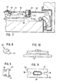
- the base plate 3 is screwed onto the supporting wall 2, which can consist of a cabinet wall or another carcass part, and is provided with fastening holes 4, 5 for its fastening.
- the Rectangular base plate 3 is provided in its central region with a holding block 6 which is extended in an H-shape on both sides by webs 7.
- the holding block 6 with the webs 7 that extend this forms a cross-sectionally rectangular holding and guiding part for a cover plate 8 screwed onto it.
- the cover plate 8 consists of a U-shaped sheet metal, the web part of which has an elongated hole 9 and at its front end an outwardly open slot 10 is provided.
- the cover plate 8 is screwed to the base plate 3 by a retaining screw 11 which is screwed into a threaded bore 12 of the holding block 6 in such a way that the legs 13, 14 of the cover plate 8 overlap the guide part formed by the holding block 6 and the webs 7 .
- the elongated hole 9 enables a longitudinal displacement of the cover plate and thus also of the hinge arm relative to the base plate 3.
- the lower edges of the legs 13, 14 of the cover plate 8 screwed onto the base plate 3 end at such a distance above the lateral regions of the base plate 3 that 7 guide grooves 15 are formed on both sides of the webs 15 for webs 16 of the hinge arm, which are formed by the legs 17 of the Hinge arms 1 are angled inwards.
- the legs 13, 14 of the cover plate 8 are provided in their rear end regions with extensions 18, 19 which abut the base plate 3 and thus, in the manner shown in FIG. 1, form stops 16 for the webs 16 inserted into the guide grooves 15.
- the legs 17 of the hinge arm are provided with bores 20, 21 for bearing bolts of the hinge joint.
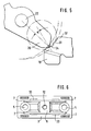
- a bearing pin 22, on which the locking lever 23 is mounted, is fastened in the rear region of the hinge arm 1 between the legs 17.
- the locking lever 23 is in the from FIG. 1, 2 and 4 evidently U-shaped.
- the legs 25, 26, which form the locking levers and are provided with cutting edges 27 at their lower free ends, are angled away from the web part 24, which forms an opening button.
- the locking lever 23 is mounted in holes in its legs on the bearing pin 22, so that it is formed with two arms.
- a leaf spring 27 is supported on the bearing axis 22, the ends of which rest against the web parts of the locking lever 23 and the hinge arm 1 with prestress.
- the web part of the hinge arm 1 is further provided with a window 28 in order to be able to reach the fastening screw 11 and with a flared threaded hole for the adjusting screw 29.
- the adjusting screw 29 is provided in its lower region with an annular groove 30 which engages in the elongated hole 10.
- the legs 13, 14 of the cover plate 8 are provided in their rear area on the side opposite the extensions 18, 19 with latching flanks 31. These locking flanks are shown in an enlarged form in FIG. 5. As long as the angle of friction, which results from the angle between the connecting line of the cutting edge 27 with the center line of the bearing pin 22 and the normal to the locking flank 31, is smaller than the angle of friction, a secure attack of the locking lever on the locking flank and thus a locking of the Hinge arm guaranteed with the mounting plate.
- the legs 13, 14 cut free from the web portion of the cover plate 8 are approximately raised in their rear area, so that when the hinge arm 1 is pushed on, the legs 25, 26 of the locking lever 23 run over the hump 32 formed thereby and fall into their latching position with an improved snap effect can.
- the base plate 3 is provided in the area to the side next to the webs 7 with ramps 33 which rise outwards in a wedge shape and which, when the hinge arm 1 is pushed on, additionally press the webs 16 which are angled inward from its legs 17 against the lower edges of the legs 13, 14 of the cover plate 8 .
- the wedge-shaped ramps 33 are arranged in mirror image to the transverse axis of the base plate 3 in order to be able to mount the hinge arm pointing to the left as well as to the right. So that when the hinge arm is pushed on, the front ramps 33 in the pushing-on direction do not impede the pushing on, the legs 13, 14 of the cover plate are lower in the front area in the manner shown in FIG. 1.
- the legs 13, 14 of the base plate 8 are extended towards the front, rounded and bent inwards.
- the legs 41 of the latching lever 43 pivotally mounted at the rear end of the hinge arm 40 about the pivot pin 42 are provided on their outer end faces with curved curved flanks 44 which are eccentric to the latching pin 42.
- the latching flanks 44 are designed eccentrically in such a way that, in a side view, they move upwards approximately spirally from the central axis of the hinge pin 42.
- the locking lever 43 is acted upon by the S-shaped leaf spring 45, which it tries to pivot clockwise in FIG. 7.
- the leaf spring 44 is supported in its central region on the hinge pin 42 and with its end regions on the web parts of the hinge arm 40 and the locking lever 43.
- the web part 46 of the locking lever 43 simultaneously forms the opening button.
- the intermediate or cover plate 47 is U-shaped in cross section formed and has a central elongated hole 48 for the fastening screw 49 and at its ends open to the outside elongated holes 49, 50, in which the annular groove 52 of the adjusting screw 51 engages in the manner shown in FIG. 7.
Landscapes
- Engineering & Computer Science (AREA)
- Mechanical Engineering (AREA)
- Hinges (AREA)
Abstract
Description
- Die Erfindung betrifft einen Scharnierarm mit Befestigungsplatte, von denen ein Teil mit einem federbelasteten schwenkbaren Hebel und der andere mit einem von dem Hebel hintergriffenen Widerlager versehen sind, die nach Einsetzen des Scharnierarms in eine Führung der Befestigungsplatte und Verschieben in Längsrichtung in ihre wieder lösbare, miteinander verrastete Stellung schnappen, und mit einem Anschlag, der bei oder nach dem Einschnappen der miteinander verrastenden Teile den Verschiebeweg begrenzt.
- Bei einem aus der europäischen Patentveröffentlichung 43 903 bekannten Scharnierarm mit Befestigungsplatte dieser Art wird die Verrastung durch einen mit einem Rastvorsprung versehenen Hebel bewirkt, der in einer Rastöffnung des Gegenteils in der Weise eingreift, daß eine keilförmige Flanke des Rastvorsprungs selbstspannend an dieser angreift, so daß der Scharnierarm spielfrei am Anschlag der Befestigungsplatte gehalten ist. Die bekannte Schnappverbindung ermöglicht eine schnelle und einfache Montage von Scharniergelenken dadurch, daß der Scharnierarm nur auf die vormontierte Befestigungsplatte aufgeschoben zu werden braucht. Da die Flanke des federbelasteten Rastvorsprungs ständig einen Schub auf den Randbereich der Rastöffnung ausübt, sind die Befestigungsplatte und der Scharnierarm spielfrei miteinander verspannt. Diese bekannte Schnappverbindung zur Befestigung des Scharnierarms an der Befestigungsplatte ist jedoch relativ aufwendig und eine gute selbstspannende Wirkung wird nur erreicht, wenn der Rasthebel von einer relativ starken Feder beaufschlagt ist.
- Aufgabe der Erfindung ist es daher, den bekannten Scharnierarm bei verbesserter selbstspannender Wirkung konstruktiv zu vereinfachen.
- Erfindungsgemäß wird diese Aufgabe dadurch gelöst, daß der Hebel und das Widerlager einerseits eine abgeschrägte oder abgerundete Rastflanke und andererseits eine Abstützkante aufweisen, die sich aufeinander mit einem kleineren Winkel als dem Reibungswinkel abstützen. Bei dem erfindungsgemäßen Scharnierarm wird auf einfache Weise dessen Verriegelung mit der Befestigungsplatte dadurch erreicht, daß sich der Rasthebel und das Widerlager schräg oder rechtwinkelig zu der Rastflanke aufeinander abstützen und der Rasthebel in der Weise auf Druck beansprucht wird, daß bei einem Zug auf den Scharnierarm derRasthebel mit größerer Sperrkraft an dem Widerlager angreift. Die sperrende Wirkung wird im wesentlichen nur durch die von dem Hebel oder dem Widerlager auf die Rastfläche ausgeübte Reibkraft bewirkt, so daß die den Hebel belastende Feder sehr schwach ausgebildet sein kann, da diese den Rasthebel nur gegen das Widerlager zu verschwenken braucht, wenn eine Lockerung oder zwischen beiden ein Spiel auftreten sollte.
- Bei dem erfindungsgemäßen Scharnierarm kann die Rastflanke an dem Hebel oder aber auch an dem Widerlager ausgebildet sein, während das andere Teil die Abstützkante oder Abstützfläche aufweist.
- Die Abstützung der Abstützkante oder Abstützfläche auf der Rastflanke findet sich zweckmäßigerweise zwischen dem Gelenkbolzen des Hebels und dem vorderen, mit den Lagerbohrungen versehenen Ende des Scharnierarms.
- Aufgrund des gewählten Reibungswinkels trachtet die auf den Hebel durch die Abstützung auf dem Widerlager wirkende Reibungskraft diesen Verriegelungsrichtung zu verschwenken. Die erforderliche Abstützkraft kann dabei auch durch die Schwerkraft des Hebels erreicht werden, die durch die Federkraft unterstützt wird.
- Zweckmäßigerweise besteht der Scharnierarm aus einem U-förmig gebogenen Blechstanzteil, wobei der Hebel in dessen Endbereich auf einem zwischen dessen Schenkeln befestigten Lagerbolzen gelagert ist. Bei dieser Ausgestaltung ist der Scharnierarm in seinem Endbereich mit der Befestigungsplatte verriegelt, so daß aufgrund des großen wirksamen Hebelarms des Scharnierarms eine stabile Befestigung gewährleistet ist.
- Die Rastflanke kann sowohl an dem Scharnierarm als auch an der Befestigungsplatte vorgesehen sein. Eine einfachere Konstruktion ergibt sich jedoch, wenn die Rastflanke am hinteren Ende der Befestigungsplatte vorgesehen ist.
- Die Führung für von den Schenkeln des Scharnierarms abgebogene Stege kann zwischen einer Grundplatte mit einem aufgesetzten Halteblock und den gegen die Grundplatte gerichteten Rändern der Schenkel einer auf diese aufgeschraubten U-förmigen Deckplatte, die beide die Befestigungsplatte bilden, vorgesehen sein.
- Zweckmäßigerweise sind die Rastflanken an den hinteren Endbereichen der Schenkel der Deckplatte vorgesehen.
- In weiterer Ausgestaltung der Erfindung ist vorgesehen, daß der Hebel aus einem U-förmig gebogenen Blechteil besteht, dessen Schenkel paarweise mit den Rastflanken zusammenwirkende Rasthebel bilden. Der zweiarmig ausgebildete Hebel kann in Bohrungen seiner Schenkel auf dem zwischen den Schenkeln des Scharnierarms befestigten Lagerbolzen gelagert sein, wobei dessen Stegteil eine zwischen den freigeschnittenen Schenkeln liegende Öffnungstaste bildet. Diese Öffnungstaste läßt sich von Hand leicht betätigen, da sie nur von geringer Federkraft beaufschlagt zu sein braucht und mit dem Niederdrücken der Öffnungstaste zugleich auch der Scharnierarm von der Befestigungsplatte abgeschoben werden kann.
- Zwischen dem Stegteil des Scharnierarms und des Hebels sowie dem zwischen diesen liegenden Lagerbolzen kann eine Blattfeder eingespannt sein, die so vorgespannt ist, daß sie den mit dem Stegteil versehenen Hebelarm anzuheben trachtet, so daß der Sperrhebel gegen die das Widerlager bildende-Flanke gedrückt wird.
- Der Rasthebel kann an seinem vorderen Ende mit einer schneidenartigen Spitze versehen sein, mit der er sich auf der Rastflanke abstützt. Durch diese Spitze wird der Reibungskoeffizient vergrößert, so daß sich auch der Reibungswinkel vergrößert.
- Die das Widerlager bildende Flanke kann verhältnismäßig flach geneigt sein, so daß eine Verrastung des Scharnierarms mit der Befestigungsplatte über einen relativ langen Weg gewährleistet ist.
- Nach einer zweckmäßigen Ausgestaltung ist vorgesehen, daß die Rastflanke durch die Stirnfläche bzw. Stirnflächen des bzw. der Schenkel des Hebels gebildet sind. Bei dieser Ausgestaltung kann das Widerlager durch die hintere Kante des Stegteils der Deckplatte gebildet sein.
- Zweckmäßigerweise sind die Grundplatte und die Deckplatte symmetrisch zu ihren Längs- und Quermittellinien ausgebildet, so daß eine einfache Links- und Rechtsmontage möglich ist. Die Endbereiche der durch die Schenkel der Deckplatte gebildeten Seitenwände sind zweckmäßigerweise zur Schaffung keilförmig erweiterter Einlaufbereiche für die Führungen abgeschrägt.
- Weitere vorteilhafte Ausgestaltungen der Erfindung sind in den Unteransprüchen beschrieben worden.
- Ein Ausführungsbeispiel der Erfindung wird nachstehend anhand der Zeichnung näher erläutert. In dieser zeigt
- Fig. 1 einen Längsschnitt durch den mit der Befestigungsplatte verrasteten Scharnierarm,
- Fig. 2 einen Längsschnitt durch den von der Befestigungsplatte gelösten Scharnierarm,
- Fig. 3 eine Unteransicht der mit der Grundplatte verschraubten Deckplatte,
- Fig. 4 eine Rückansicht der Deckplatte nach Fig. 3,
- Fig. 5 eine vergrößerte Darstellung des auf der gekrümmten Rastflanke abgestützten Rasthebels in Seitenansicht,
- Fig. 6 eine Draufsicht auf die Grundplatte bei abgehobener Deckplatte,
- Fig. 7 einen Längsschnitt durch eine zweite Ausfühführungsform eines mit der Befestigungsplatte verrasteten Scharnierarms,
- Fig. 8 eine Seitenansicht des Rasthebels des Scharnierarms nach Fig. 7,
- Fig. 9 eine Draufsicht auf den Rasthebel nach Fig. 8,
- Fig.10 eine Seitenansicht der aus Grund- und Deckplatte bestehenden Befestigungsplatte nach Fig. 7 und
- Fig.11 eine Draufsicht auf die Deckplatte nach den Fig. 7 und 10.
- Zur Montage des Scharnierarms 1 wird auf die Tragwand 2, die aus einer Schrankwand oder einem anderen Korpusteil bestehen kann, in üblicher Weise die Grundplatte 3 aufgeschraubt, die zu ihrer Befestigung mit Befestigungsbohrungen 4, 5 versehen ist. Die rechteckige Grundplatte 3 ist in ihrem mittleren Bereich mit einem Halteblock 6 versehen, der H-förmig nach beiden Seiten durch Stege 7 verlängert ist. Der Halteblock 6 mit den diesen verlängernden Stegen 7 bildet ein im Querschnitt rechteckiges Halte- und Führungsteil für eine auf diese aufgeschraubte Deckplatte 8. Die Deckplatte 8 besteht aus einem U-förmig gebogenen Blech, dessen Stegteil mit einem Langloch 9 und an seinem vorderen Ende mit einem nach außen offenen Langloch 10 versehen ist. Die Deckplatte 8 ist durch eine Halteschraube 11, die in eine Gewindebohrung 12 des Halteblocks 6 eingeschraubt ist, in der Weise mit der Grundplatte 3 verschraubt, daß die Schenkel 13, 14 der Deckplatte 8 das durch den Halteblock 6 und die Stege 7 gebildete Führungsteil übergreifen. Dabei ermöglicht das Langloch 9 eine Längsverschiebung der Deckplatte und damit auch des Scharnierarms relativ zur Grundplatte 3.
- Die unteren Ränder der Schenkel 13, 14 der auf die Grundplatte 3 aufgeschraubten Deckplatte 8 enden in einem solchen Abstand oberhalb der seitlichen Bereiche der Grundplatte 3, daß beidseits der Stege 7 Führungsnuten 15 für Stege 16 des Scharnierarms gebildet sind, die von den Schenkeln 17 der Scharnierarme 1 nach innen hin abgewinkelt sind.
- Die Schenkel 13, 14 der Deckplatte 8 sind in ihren hinteren Endbereichen mit Fortsätzen 18, 19 versehen, die bis auf die Grundplatte 3 stoßen und somit in der aus Fig. 1 ersichtlichen Weise Anschläge für die in die Führungsnuten 15 eingeschobenen Stege 16-bilden.
- In ihrem vorderen Bereich sind die Schenkel 17 des Scharnierarms mit Bohrungen 20, 21 für Lagerbolzen des Scharniergelenks versehen. Zwischen den Schenkeln 17 ist im hinteren Bereich des Scharnierarms 1 ein Lagerbolzen 22 befestigt, auf dem der Sperrhebel 23 gelagert ist. Der Sperrhebel 23 ist in der aus den Fig. 1, 2 und 4 ersichtlichen Weise U-förmig ausgebildet. Dabei sind von dem Stegteil 24, der eine Öffnungstaste bildet, die Schenkel 25, 26 abgewinkelt, die die Rasthebel bilden und an ihren unteren freien Enden mit Schneiden 27 versehen sind. Der Sperrhebel 23 ist in Bohrungen seiner Schenkel auf dem Lagerbolzen 22 gelagert, so daß er zweiarmig ausgebildet ist. Auf der Lagerachse 22 ist eine Blattfeder 27 abgestützt, deren Enden jeweils mit Vorspannung an den Stegteilen des Rasthebels 23 und des Scharnierarms 1 anliegen.
- Das Stegteil des Scharnierarms 1 ist weiterhin mit einem Fenster 28, um die Befestigungsschraube 11 erreichen zu können, und mit einer aufgebördelten Gewindebohrung für die Stellschraube 29 versehen. Die Stellschraube 29 ist in ihrem unteren Bereich mit einer Ringnut 30 versehen, die in das Langloch 10 eingreift.
- Die Schenkel 13, 14 der Deckplatte 8 sind in ihrem hinteren Bereich auf der den Fortsätzen 18, 19 gegenüberliegenden Seite mit Rastflanken 31 versehen. Diese Rastflanken sind in Fig. 5 in vergrößerter Form dargestellt. Solange der Reibungswinkel , der sich aus dem Winkel zwischen der Verbindungslinie der Schneide 27 mit der Mittellinie des Lagerbolzens 22 und der Normalen auf die Rastflanke 31 ergibt, kleiner ist als der Reibungswinkel, ist ein sicherer Angriff des Rasthebels auf der Rastflanke und damit eine Verriegelung des Scharnierarms mit der Befestigungsplatte gewährleistet.
- Die von dem Stegteil der Deckplatte 8 freigeschnittenen Schenkel 13, 14 sind in ihrem hinteren Bereich etwa überhöht, so daß beim Aufschieben des Scharnierarms 1 die Schenkel 25, 26 des Rasthebels 23 den dadurch gebildeten Buckel 32 überfahren und mit verbessertem Schnappeffekt in ihre verrastende Stellung einfallen können.
- Die Grundplatte 3 ist im Bereich seitlich neben den Stegen 7 mit nach außen keilförmig ansteigenden Rampen 33 versehen, die beim Aufschieben des Scharnierarms 1 die von dessen Schenkeln 17 nach innen abgewinkelten Stege 16 zusätzlich gegen die unteren Ränder der Schenkel 13, 14 der Deckplatte 8 andrücken. Die keilförmigen Rampen 33 sind spiegelbildlich zur Querachse der Grundplatte 3 angeordnet, um den Scharnierarm sowohl nach links als auch nach rechts weisend auf dieser montieren zu können. Damit beim Aufschieben des Scharnierarms die in Aufschubrichtung vorderen Rampen 33 das Aufschieben nicht behindern, sind die Schenkel 13, 14 der Deckplatte in der aus Fig. 1 ersichtlichen Weise im vorderen Bereich niedriger.
- Die Schenkel 13, 14 der Grundplatte 8 sind nach vorne hin verlängert, abgerundet und nach innen hin eingebogen.
- Bei der Ausführungsform nach den Fig. 7 bis 11 sind die Schenkel 41 des am hinteren Ende des Scharnierarms 40 um den Gelenkbolzen 42 schwenkbar gelagerten Rasthebels 43 an ihren äußeren Stirnflächen mit kurvenförmig gekrümmten, zu dem Rastbolzen 42 exzentrischen Rastflanken 44 versehen. Die Rastflanken 44 sind derart exzentrisch ausgebildet, daß sie in Seitenansicht sich nach oben hin etwa spiralig von der Mittelachse des Gelenkbolzens 42 entfernen.
- Der Rasthebel 43 wird von der S-förmig gekrümmten Blattfeder 45 beaufschlagt, die sie in Fig. 7 im Uhrzeigersinn zu verschwenken trachtet. Die Blattfeder 44 stützt sich in ihrem mittleren Bereich auf dem Gelenkbolzen 42 und mit ihren Endbereichen auf den Stegteilen des Scharnierarms 40 und des Rasthebels 43 ab. Der Stegteil 46 des Rasthebels 43 bildet gleichzeitig die Öffnungstaste.
- Die Zwischen- oder Deckplatte 47 ist im Querschnitt U-förmig ausgebildet und weist ein mittleres Langloch 48 für die Befestigungsschraube 49 und an ihren Enden nach außen hin offene Langlöcher 49, 50 auf, in die in der aus Fig. 7 ersichtlichen Weise die Ringnut 52 der Stellschraube 51 greift.
- Die oberen hinteren Stirnkanten 53 des Stegteils der Deckplatte 57 bilden die Widerlager für die Rastflanken 44 des Rasthebels 43. Im montierten Zustand stützt sich das Schaftteil der Stellschraube 51 im Grund der Ringnut 52 auf das Endteil des Langlochs 49, 50 ab und wird gegen dieses unter den spannenden Wirkung, die die Rastflanke 44 auf die Abstützkanten 53 ausübt, angedrückt.
Claims (21)
Priority Applications (1)
| Application Number | Priority Date | Filing Date | Title |
|---|---|---|---|
| AT84113657T ATE40437T1 (de) | 1983-12-13 | 1984-11-12 | Scharnierarm mit befestigungsplatte. |
Applications Claiming Priority (4)
| Application Number | Priority Date | Filing Date | Title |
|---|---|---|---|
| DE3345063 | 1983-12-13 | ||
| DE19833345063 DE3345063C2 (de) | 1983-12-13 | 1983-12-13 | Scharnierarm mit Befestigungsplatte |
| DE3427607 | 1984-07-26 | ||
| DE3427607 | 1984-07-26 |
Publications (3)
| Publication Number | Publication Date |
|---|---|
| EP0145952A2 true EP0145952A2 (de) | 1985-06-26 |
| EP0145952A3 EP0145952A3 (en) | 1986-05-21 |
| EP0145952B1 EP0145952B1 (de) | 1989-01-25 |
Family
ID=25816401
Family Applications (1)
| Application Number | Title | Priority Date | Filing Date |
|---|---|---|---|
| EP84113657A Expired EP0145952B1 (de) | 1983-12-13 | 1984-11-12 | Scharnierarm mit Befestigungsplatte |
Country Status (5)
| Country | Link |
|---|---|
| US (1) | US4674148A (de) |
| EP (1) | EP0145952B1 (de) |
| BR (1) | BR8406381A (de) |
| DE (1) | DE3476434D1 (de) |
| ES (1) | ES293461Y (de) |
Cited By (4)
| Publication number | Priority date | Publication date | Assignee | Title |
|---|---|---|---|---|
| DE3521051A1 (de) * | 1985-06-12 | 1986-12-18 | Arturo Salice S.P.A., Novedrate, Como | Scharnierarm fuer ein moebelscharnier mit befestigungsplatte |
| DE3640012A1 (de) * | 1986-11-24 | 1988-06-01 | Salice Arturo Spa | Zweiteiliger verbindungsbeschlag |
| US4850080A (en) * | 1986-04-10 | 1989-07-25 | Julius Blum Gesellschaft M.B.H. | Hinge |
| US5224242A (en) * | 1991-07-16 | 1993-07-06 | Mednarodno Podjetje Lama, D.D. | Quick-assembling furniture hinge |
Families Citing this family (4)
| Publication number | Priority date | Publication date | Assignee | Title |
|---|---|---|---|---|
| DE3744906C2 (de) * | 1987-10-06 | 1994-11-03 | Grass Ag | Möbelscharnier mit Rastmechanik |
| AT1214U1 (de) * | 1995-12-18 | 1996-12-27 | Blum Gmbh Julius | Scharnier |
| WO2015068714A1 (ja) * | 2013-11-11 | 2015-05-14 | スガツネ工業株式会社 | ヒンジ装置及びヒンジ装置基部 |
| USD974877S1 (en) * | 2020-04-30 | 2023-01-10 | Draper, Inc. | Electronic display mount |
Family Cites Families (10)
| Publication number | Priority date | Publication date | Assignee | Title |
|---|---|---|---|---|
| DE352577C (de) * | 1920-06-21 | 1922-04-29 | Escher Wyss Maschf Ag | Vorrichtung zur Beeinflussung des Betriebes einer mit einem durch fliessendes Wasser gekuehlten Kondensator ausgestatteten und durch einen Motor angetriebenen Kaeltemaschine |
| AT340274B (de) * | 1973-07-12 | 1977-12-12 | Blum Gmbh Julius | Scharnier mit einer klemmvorrichtung |
| AT352577B (de) * | 1973-12-21 | 1979-09-25 | Blum Gmbh | Einstellbares scharnier mit einem zwischen- stueck und einer grundplatte |
| AT333616B (de) * | 1974-04-01 | 1976-12-10 | Blum Gmbh | Langen- und tiefeneinstellbares scharnier mit einem elastischen zwischenstuck |
| IT7521594U1 (it) * | 1975-06-03 | 1976-12-03 | Salice Arturo Spa | Ferramento per mobili ad innesto rapido con registrazione tridimensionale. |
| AT371205B (de) * | 1977-02-28 | 1983-06-10 | Blum Gmbh Julius | Halte- bzw. verriegelungseinrichtung fuer ein zwischenstueck eines scharnieres |
| DE3161939D1 (en) * | 1980-07-15 | 1984-02-23 | Salice Arturo Spa | Hinge arm with mounting plate |
| DE3043334C2 (de) * | 1980-11-17 | 1985-04-04 | Arturo Salice S.P.A., Novedrate, Como | Scharnierarm mit Befestigungsplatte |
| DE3043789C2 (de) * | 1980-11-20 | 1983-01-13 | Arturo Salice S.p.A., 22060 Novedrate, Como | Scharnierarm mit Befestigungsplatte |
| EP0097766B1 (de) * | 1982-06-26 | 1985-11-21 | Karl Lautenschläger KG Möbelbeschlagfabrik | Möbelscharnier |
-
1984
- 1984-11-12 EP EP84113657A patent/EP0145952B1/de not_active Expired
- 1984-11-12 DE DE8484113657T patent/DE3476434D1/de not_active Expired
- 1984-11-29 US US06/676,421 patent/US4674148A/en not_active Expired - Fee Related
- 1984-12-12 ES ES1984293461U patent/ES293461Y/es not_active Expired
- 1984-12-12 BR BR8406381A patent/BR8406381A/pt unknown
Cited By (7)
| Publication number | Priority date | Publication date | Assignee | Title |
|---|---|---|---|---|
| DE3521051A1 (de) * | 1985-06-12 | 1986-12-18 | Arturo Salice S.P.A., Novedrate, Como | Scharnierarm fuer ein moebelscharnier mit befestigungsplatte |
| EP0205026A3 (en) * | 1985-06-12 | 1987-05-13 | Salice S.P.A. Arturo | Hinge arm for a furniture hinge with a mounting plate |
| US4850080A (en) * | 1986-04-10 | 1989-07-25 | Julius Blum Gesellschaft M.B.H. | Hinge |
| DE3640012A1 (de) * | 1986-11-24 | 1988-06-01 | Salice Arturo Spa | Zweiteiliger verbindungsbeschlag |
| EP0275405A3 (en) * | 1986-11-24 | 1988-10-05 | Salice S.P.A. Arturo | Connection fitting made of two parts |
| US4823436A (en) * | 1986-11-24 | 1989-04-25 | Arturo Salice S.P.A. | Two-part connecting fixture for furniture which includes a sprung-detent locking lever |
| US5224242A (en) * | 1991-07-16 | 1993-07-06 | Mednarodno Podjetje Lama, D.D. | Quick-assembling furniture hinge |
Also Published As
| Publication number | Publication date |
|---|---|
| BR8406381A (pt) | 1985-10-08 |
| EP0145952A3 (en) | 1986-05-21 |
| DE3476434D1 (en) | 1989-03-02 |
| ES293461Y (es) | 1987-04-16 |
| EP0145952B1 (de) | 1989-01-25 |
| US4674148A (en) | 1987-06-23 |
| ES293461U (es) | 1986-08-01 |
Similar Documents
| Publication | Publication Date | Title |
|---|---|---|
| EP0043903B2 (de) | Scharnierarm mit Befestigungsplatte | |
| DE2633972C3 (de) | Anordnung zum Verbinden zweier Bauteile | |
| DE2412500C3 (de) | Spannverschluß | |
| DE3026796C2 (de) | Scharnier mit einem Scharnierarm und einer Befestigungsplatte | |
| CH667139A5 (de) | Verbindungsbeschlag. | |
| DE9319125U1 (de) | Verbindungselement zum Verbinden eines Holzbauteils mit einem zweiten Bauteil | |
| DE19941499A1 (de) | Verbindungsstück zum Verbinden eines Wischblatts mit einem Wischerarm | |
| DE3311219A1 (de) | Vorrichtung zum verbinden eines wischerarmes mit einem wischerblatt | |
| DE3828277C2 (de) | An einer Tragschiene anbringbare Schalteinheit mit zwei elektromagnetischen Kontakteinrichtungen | |
| DE3119176C2 (de) | Vorrichtung zum Verbinden eines Windschutzscheibenwischerarms mit einem Windschutzscheiben-Wischerblatt | |
| EP0052283A2 (de) | Scharnierarm mit Befestigungsplatte | |
| EP0466289B1 (de) | Scharnieranordnung für die Tür eines Schaltschrankes | |
| EP0145952B1 (de) | Scharnierarm mit Befestigungsplatte | |
| DE3042057A1 (de) | Schraubenlose klemme | |
| DE2901213A1 (de) | Loesbare stiftverbindung fuer bauelemente | |
| EP0275405A2 (de) | Zweiteiliger Verbindungsbeschlag | |
| DE3345063C2 (de) | Scharnierarm mit Befestigungsplatte | |
| DE3307777C2 (de) | Verdecktes Scharniergelenk mit Zuhalteeinrichtung | |
| DE3214526A1 (de) | Vorrichtung zur laengsverstellung von skibindungsteilen | |
| DE3808776A1 (de) | Gelenkverbindung | |
| DE69011489T2 (de) | Verbindungselemente für Rückenlehnen mit dazugehörigen Sitzen. | |
| DE69510627T2 (de) | Geräteträgereinrichtung Einzubringen auf einen Kabelkanalkörper | |
| DE8435622U1 (de) | Scharnierarm mit befestigungsplatte | |
| DE2909114C2 (de) | Anordnung zum Befestigen von Bauteilen auf Tragplatten, insbesondere einer Leiterplatte in einem Gerät der Nachrichtentechnik | |
| EP1230490B1 (de) | Befestigungselement zum lösbaren verbinden von rechtwinklig zueinander angeordneten blechplatten |
Legal Events
| Date | Code | Title | Description |
|---|---|---|---|
| PUAI | Public reference made under article 153(3) epc to a published international application that has entered the european phase |
Free format text: ORIGINAL CODE: 0009012 |
|
| AK | Designated contracting states |
Designated state(s): AT DE FR GB IT |
|
| RTI1 | Title (correction) | ||
| PUAL | Search report despatched |
Free format text: ORIGINAL CODE: 0009013 |
|
| AK | Designated contracting states |
Kind code of ref document: A3 Designated state(s): AT DE FR GB IT |
|
| 17P | Request for examination filed |
Effective date: 19860802 |
|
| 17Q | First examination report despatched |
Effective date: 19871007 |
|
| GRAA | (expected) grant |
Free format text: ORIGINAL CODE: 0009210 |
|
| AK | Designated contracting states |
Kind code of ref document: B1 Designated state(s): AT DE FR GB IT |
|
| REF | Corresponds to: |
Ref document number: 40437 Country of ref document: AT Date of ref document: 19890215 Kind code of ref document: T |
|
| ITF | It: translation for a ep patent filed | ||
| REF | Corresponds to: |
Ref document number: 3476434 Country of ref document: DE Date of ref document: 19890302 |
|
| ET | Fr: translation filed | ||
| GBT | Gb: translation of ep patent filed (gb section 77(6)(a)/1977) | ||
| PLBE | No opposition filed within time limit |
Free format text: ORIGINAL CODE: 0009261 |
|
| STAA | Information on the status of an ep patent application or granted ep patent |
Free format text: STATUS: NO OPPOSITION FILED WITHIN TIME LIMIT |
|
| 26N | No opposition filed | ||
| PGFP | Annual fee paid to national office [announced via postgrant information from national office to epo] |
Ref country code: GB Payment date: 19901024 Year of fee payment: 7 |
|
| PGFP | Annual fee paid to national office [announced via postgrant information from national office to epo] |
Ref country code: FR Payment date: 19901109 Year of fee payment: 7 |
|
| PG25 | Lapsed in a contracting state [announced via postgrant information from national office to epo] |
Ref country code: GB Effective date: 19911112 |
|
| ITTA | It: last paid annual fee | ||
| PGFP | Annual fee paid to national office [announced via postgrant information from national office to epo] |
Ref country code: DE Payment date: 19911130 Year of fee payment: 8 |
|
| GBPC | Gb: european patent ceased through non-payment of renewal fee | ||
| PG25 | Lapsed in a contracting state [announced via postgrant information from national office to epo] |
Ref country code: FR Effective date: 19920731 |
|
| REG | Reference to a national code |
Ref country code: FR Ref legal event code: ST |
|
| PG25 | Lapsed in a contracting state [announced via postgrant information from national office to epo] |
Ref country code: DE Effective date: 19930803 |
|
| PGFP | Annual fee paid to national office [announced via postgrant information from national office to epo] |
Ref country code: AT Payment date: 20001122 Year of fee payment: 17 |
|
| PG25 | Lapsed in a contracting state [announced via postgrant information from national office to epo] |
Ref country code: AT Free format text: LAPSE BECAUSE OF NON-PAYMENT OF DUE FEES Effective date: 20011112 |