EP0146029A2 - Véhicule franchissant des escaliers - Google Patents
Véhicule franchissant des escaliers Download PDFInfo
- Publication number
- EP0146029A2 EP0146029A2 EP84114350A EP84114350A EP0146029A2 EP 0146029 A2 EP0146029 A2 EP 0146029A2 EP 84114350 A EP84114350 A EP 84114350A EP 84114350 A EP84114350 A EP 84114350A EP 0146029 A2 EP0146029 A2 EP 0146029A2
- Authority
- EP
- European Patent Office
- Prior art keywords
- vehicle
- vehicle according
- roller
- rollers
- chassis
- Prior art date
- Legal status (The legal status is an assumption and is not a legal conclusion. Google has not performed a legal analysis and makes no representation as to the accuracy of the status listed.)
- Granted
Links
Images
Classifications
-
- A—HUMAN NECESSITIES
- A61—MEDICAL OR VETERINARY SCIENCE; HYGIENE
- A61G—TRANSPORT, PERSONAL CONVEYANCES, OR ACCOMMODATION SPECIALLY ADAPTED FOR PATIENTS OR DISABLED PERSONS; OPERATING TABLES OR CHAIRS; CHAIRS FOR DENTISTRY; FUNERAL DEVICES
- A61G5/00—Chairs or personal conveyances specially adapted for patients or disabled persons, e.g. wheelchairs
- A61G5/06—Chairs or personal conveyances specially adapted for patients or disabled persons, e.g. wheelchairs with obstacle mounting facilities, e.g. for climbing stairs, kerbs or steps
- A61G5/061—Chairs or personal conveyances specially adapted for patients or disabled persons, e.g. wheelchairs with obstacle mounting facilities, e.g. for climbing stairs, kerbs or steps for climbing stairs
-
- A—HUMAN NECESSITIES
- A61—MEDICAL OR VETERINARY SCIENCE; HYGIENE
- A61G—TRANSPORT, PERSONAL CONVEYANCES, OR ACCOMMODATION SPECIALLY ADAPTED FOR PATIENTS OR DISABLED PERSONS; OPERATING TABLES OR CHAIRS; CHAIRS FOR DENTISTRY; FUNERAL DEVICES
- A61G5/00—Chairs or personal conveyances specially adapted for patients or disabled persons, e.g. wheelchairs
- A61G5/06—Chairs or personal conveyances specially adapted for patients or disabled persons, e.g. wheelchairs with obstacle mounting facilities, e.g. for climbing stairs, kerbs or steps
- A61G5/066—Chairs or personal conveyances specially adapted for patients or disabled persons, e.g. wheelchairs with obstacle mounting facilities, e.g. for climbing stairs, kerbs or steps with endless belts
-
- B—PERFORMING OPERATIONS; TRANSPORTING
- B62—LAND VEHICLES FOR TRAVELLING OTHERWISE THAN ON RAILS
- B62B—HAND-PROPELLED VEHICLES, e.g. HAND CARTS OR PERAMBULATORS; SLEDGES
- B62B9/00—Accessories or details specially adapted for children's carriages or perambulators
- B62B9/02—Accessories or details specially adapted for children's carriages or perambulators providing for travelling up or down a flight of stairs
-
- B—PERFORMING OPERATIONS; TRANSPORTING
- B62—LAND VEHICLES FOR TRAVELLING OTHERWISE THAN ON RAILS
- B62D—MOTOR VEHICLES; TRAILERS
- B62D55/00—Endless track vehicles
- B62D55/06—Endless track vehicles with tracks without ground wheels
- B62D55/075—Tracked vehicles for ascending or descending stairs, steep slopes or vertical surfaces
Definitions
- the invention relates to a stair-climbing vehicle according to the preamble of claim 1.
- Such a vehicle is said to be particularly suitable for the transport of disabled people in their wheelchairs and for goods on steep stairs and on level lanes.
- a caterpillar vehicle US-A 4 401 178
- an attachment wheelchair adapter
- These stair-steered caterpillars have a low chassis with two motor-driven caterpillars, which have a sliding guide that is rigid on the floor tread and angled at one end. The deflection via a roller star is also known.
- these vehicles For drive-free horizontal transport, these vehicles have transport rollers in the area of the angled caterpillar guide, which have to be inserted laterally for use or lowered to the ground using a footrest.
- the castors - which can be plugged on for horizontal transport - are tedious to use because they have to be dismantled for climbing stairs.
- the castors, which can be lowered using the footrest, require a fairly complex construction and must be operated again on each intermediate platform. The correct position is usually monitored electrically.
- the invention has for its object to improve driving safety by increasing the stability of the vehicle when steep stairs have to be mastered.
- the stair ride should be more convenient.
- the vehicle according to the invention has, on its low chassis with a caterpillar drive, an at least one-piece boom device near the ground, which projects beyond the base of the chassis on one or more sides and thus increases the support surface of the vehicle on the floor and stairs.
- the stability of the vehicle can be significantly increased both in the transverse and in the longitudinal axis. It can also be used to climb very steep stairs.
- the boom device has one or more support rollers at its end located downstream of the staircase, which enables continuous and frictionless passage over the lower start of the staircase.
- the boom device is adjustable in length and / or width, so that the support surface can be adapted to the stairs and to the transported load. This allows the external dimensions of the vehicle to be kept as small as necessary.
- the boom device is designed to be pluggable or otherwise removable. In this way, the boom device can be completely dispensed with in the case of appropriate conditions will. This also has advantages for loading the vehicle.
- the vehicle has an automatically functioning rolling device in the region of the angled crawler track.
- the roller carriers, each with two castors, which are connected via a rigid axle, can be freely rotated and therefore do not interfere with climbing the caterpillars in any way.
- the arrangement with the axle between two castors each has the advantage that the vehicle is always automatically on the protruding castors in the horizontal plane and can thus be maneuvered without further power without further manipulation.
- This user-friendly construction has the further advantage that there is no need for electrical monitoring of the system, which brings price advantages with the simple construction.
- the roller carriers of the rolling device are mounted slightly rotated with respect to one another, the weight of the vehicle lying predominantly on the rollers which slightly protrude crosswise, while the other two rollers, which stand back crosswise, assume the necessary supporting function.
- the roller carriers of the rolling device each have only one driving roller, the roller carriers in turn being rigidly connected and pivotable with no load on the connecting axis, as a result of which unobstructed movement along the stairs is also achieved.
- the necessary determination of the driving position in the hearing horizontal plane takes place here by a positive or non-positive fixing of the connecting axis, which in turn is generated automatically when entering the horizontal plane.
- the present invention is the further development of the known stair crawler for wheelchairs, in which a simple and inexpensive measure increased driving safety, easier operation and increased application possibilities can be achieved.
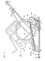
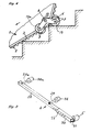
- the vehicle 20 is designed to work with a wheelchair 50, which usually has two large wheels 51, two rollers 52, a frame 54 including a seat 55 and a guide rod 56 which are arranged at a distance from one another.
- the vehicle 20 has a low, narrow chassis 1, which has space in the intermediate area between the wheels 51 and the frame 54, so that the wheelchair 50 can be underpinned for climbing stairs.
- the chassis 1 has casings 21, within which a battery, an electric motor and a worm gear are accommodated, as is known (for example from US Pat. No. 4,401,178, incorporated by reference).
- Wheels 22 and 23 are provided in pairs on the chassis 1, of which at least one pair of wheels (22) is driven.
- Caterpillars 2 in the form of nubbed rubber bands are stretched over each of the wheels 22, 23 and over a guide device 3, so that there is approximately a wedge-shaped outline.
- Each guide device 3 consists of a rail 24, which extends along the bottom of the chassis, and a further rail 25, which is arranged at an angle of approximately 130 to 150 ° to the rail 24 and extends tangentially to the wheel 23.
- the top of the vehicle 20 is taken up by a loading platform 26 and by fastening rails 27, on which a wheelchair adapter 14 can be brought into engagement.
- the wheelchair adapter 14 contains two rods 16 arranged at a distance from one another, on one end of which guide handles 15 and on the other end of which brackets 17 are provided for gripping the wheels 51.
- Retaining devices 18 are also attached to the wheelchair adapter 14 and are used to further secure the wheelchair 50 in an inclined center of gravity - in preparation for climbing stairs.
- Each boom device 4 On the vehicle 20, two boom devices 4 near the ground are also attached, which are provided with support rollers 5 at their front end.
- Each boom device 4 consists of tubes or rods 28-31 or 32-35, which are arranged in two groups.
- Each boom device 4 contains links 28, 39, 29a or 32, 33, 33a fixedly attached to the chassis 1, also telescopic links 30 or 34 and connecting links 31 or 35, on which the rollers 5 are seated.
- the two boom devices 4 can be connected to one another by a coupling member 36; however, this can also be missing.
- the links 28, 30 and 32, 34 extend parallel to the rails 24, but are located further outside, as best seen in FIG. 3. This increases the base area of the chassis 1 and thus improves the stability in the longitudinal direction and / or in the transverse direction.
- Fig. 9 shows a preferred construction of the boom device 4.
- the links 28, 30 consist of rectangular tubes which are telescopically pushed into one another and can be locked together with a cross pin 37.
- the links 29, 29a each contain a rod and a sleeve 38, 38a, which telescopically interlock and can be locked. In this way it is possible to change the distance of the rectangular tubes 28, 30 from the chassis 1 in order to increase the stability or reduce the driving width, depending on the requirements.
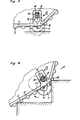
- the guide devices 3 for the caterpillars 2 have an angled point at which the two rails 24, 25 meet.
- a rolling device 13 is provided, which consists of an axle 8 rotatably mounted in the chassis 1, double-armed levers 6 attached to it and rollers 7 at the ends of the levers 6.
- the levers 6 are arranged outside the casing of the chassis and also somewhat outside the orbit of the caterpillars 2 and are shaped according to an inverted V.
- the rollers 7 protrude beyond the outline of the caterpillars 2, as can be seen in FIG. 1. In the case of a level roadway, the vehicle 20 is therefore essentially supported on the support rollers 5 and the rollers 7. This situation occurs when the vehicle enters a staircase.
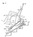
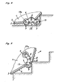
- Fig. 2 shows the vehicle 20 with a wheelchair 50 while driving on a staircase.
- the backrest of the wheelchair 50 is directed upstairs, regardless of the direction of travel of the vehicle 20.
- the boom devices 4 remain dismantled or retracted.
- the two boom devices 4 are mounted by inserting the ends 29, 29a into corresponding locations on the chassis, for example in sleeves 38, 38a, as shown in FIG. 9.
- the length of the boom devices is adapted to the circumstances by the telescopic members 28, 30 and 32, 34 shifted more or less far into each other and torn be valid.
- the increased stability is in fact bought by a certain reduction in maneuverability in the horizontal plane, which is why the boom device is only extended as far as necessary.
- the information on this is provided by a protractor with corresponding markings.
- the respective rollers 7 are rotatably attached to the ends of the double-armed levers 6 on an axis 19, 19a, 19b, 19c.
- the axes 19, 19b and 19a, 19c are arranged slightly offset from one another, ie the axes 19, 19c run somewhat lower than the axes 19a, 19b.
- the double-armed levers 6 are rigidly fixed on the axle 8 on both sides of the chassis, rotated relative to one another. It is thereby achieved that, when supported on a flat surface, only one roller on each chassis side is seated, for example the rollers 7 seated on the axes 19, 19c, so that the rollers 7 protrude "crosswise" or stand back crosswise.
- This arrangement offers advantages when maneuvering, which is particularly important on narrow steps.
- the accompanying person can namely shift the focus on the rear rollers 7 by pressing the guide handles 15 and then turn the vehicle without having to overcome such a high resistance as would otherwise occur with double rollers.
- rollers 7 Due to the arrangement of the rollers 7 at the ends of the double-armed lever 6, the rollers 7 have such a mobility that they avoid the "obstacle stair nosing", as best seen in FIGS. 2, 5 and 6.
- the vehicle 20 rests only on the caterpillars 2 and cannot be supported on a stair nosing with the rollers 7. On the other hand, this means that the rolling device 13 does not hinder the stairs.
- the double-armed levers 6 are angular, the two levers each pointing obliquely downwards.
- the rollers 7 have a tendency to assume a lower position due to gravity. So if that If the vehicle arrives on a pedestal after climbing a staircase, as is shown, for example, in FIG. 4 for the descent, the vehicle lands on the rollers 7 and can be pushed without any drive and, if necessary, turned, as already described. The front end of the support rollers 5 lifts a little off the ground and thus does not hinder the turning maneuver.
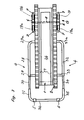
- a modification of the rolling device 13 is shown.
- keyhole-like recesses 11 are provided, and the axis 8 has flattened ends which sit in these recesses 11, so that a corresponding link guide is provided.
- the lower, bore-like area 12 of the recess 11 enables the axis 8 to be rotated, while the axis 8 is secured against rotation in the upper groove-shaped area.
- a roller carrier 9 is rigidly connected to the axis 8, and a roller or a pair of rollers 7 is seated on the roller carrier 9.
- the axis 8 slides with its flats 10 into the groove-shaped part of the recess 11 and finally finds resistance, as shown in FIG. 7.
- the vehicle 20 can now be maneuvered on the rollers 7, as already described.
- the axis 9 enters the bore-like part 12 of the recess 11, so that the rollers 7 can pivot away and do not constitute an obstacle to climbing stairs.
- the effect of gravity on the rollers 7 can also be supported by spring force, so that the position shown in Fig. 8 is safely assumed.
- the boom device 4 can also be formed in one piece, for example consist of a sheet metal.
Landscapes
- Engineering & Computer Science (AREA)
- Health & Medical Sciences (AREA)
- Public Health (AREA)
- Life Sciences & Earth Sciences (AREA)
- Animal Behavior & Ethology (AREA)
- General Health & Medical Sciences (AREA)
- Veterinary Medicine (AREA)
- Chemical & Material Sciences (AREA)
- Combustion & Propulsion (AREA)
- Transportation (AREA)
- Mechanical Engineering (AREA)
- Handcart (AREA)
Applications Claiming Priority (2)
| Application Number | Priority Date | Filing Date | Title |
|---|---|---|---|
| CH66181/83 | 1983-12-12 | ||
| CH6618/83A CH663934A5 (de) | 1983-12-12 | 1983-12-12 | Fahrzeug zum transport von personen und guetern auf treppen. |
Publications (3)
| Publication Number | Publication Date |
|---|---|
| EP0146029A2 true EP0146029A2 (fr) | 1985-06-26 |
| EP0146029A3 EP0146029A3 (en) | 1985-12-27 |
| EP0146029B1 EP0146029B1 (fr) | 1988-03-30 |
Family
ID=4312404
Family Applications (1)
| Application Number | Title | Priority Date | Filing Date |
|---|---|---|---|
| EP84114350A Expired EP0146029B1 (fr) | 1983-12-12 | 1984-11-28 | Véhicule franchissant des escaliers |
Country Status (4)
| Country | Link |
|---|---|
| US (1) | US4627508A (fr) |
| EP (1) | EP0146029B1 (fr) |
| CH (1) | CH663934A5 (fr) |
| DE (1) | DE3470116D1 (fr) |
Cited By (8)
| Publication number | Priority date | Publication date | Assignee | Title |
|---|---|---|---|---|
| AU686959B2 (en) * | 1996-01-23 | 1998-02-12 | Sunwa Ltd. | Transporter for patient's emergency escape |
| RU2328259C1 (ru) * | 2007-04-02 | 2008-07-10 | Дядченко Николай Петрович | Кресло-коляска для инвалидов на колесно-гусеничном ходу |
| RU2368366C1 (ru) * | 2008-02-19 | 2009-09-27 | Александр Дмитриевич Элизов | Транспортное средство, преимущественно для перемещения человека по лестницам |
| DE202015006899U1 (de) | 2015-10-01 | 2016-02-12 | Andreas Wulff | Laufstuhl |
| CN105919739A (zh) * | 2016-06-12 | 2016-09-07 | 浙江工业大学 | 便携登阶轮椅 |
| DE102015012755A1 (de) | 2015-10-01 | 2017-04-06 | Andreas Wulff | Laufstuhl |
| DE102017006071A1 (de) | 2017-06-28 | 2019-01-03 | Ruprecht Rohde | Multifunktionsfahrzeug |
| US11097583B2 (en) | 2018-11-30 | 2021-08-24 | Ruprecht Alfred Rohde | Vehicle |
Families Citing this family (25)
| Publication number | Priority date | Publication date | Assignee | Title |
|---|---|---|---|---|
| US4915184A (en) * | 1988-06-10 | 1990-04-10 | Quest Technologies Corp. | Cushioning mechanism for stair-climbing wheelchair |
| US5248007A (en) * | 1989-11-21 | 1993-09-28 | Quest Technologies, Inc. | Electronic control system for stair climbing vehicle |
| JP2551862B2 (ja) * | 1990-10-18 | 1996-11-06 | 株式会社サンワ | 車椅子用階段昇降機 |
| JPH0872758A (ja) * | 1994-06-29 | 1996-03-19 | West Japan Railway Co | 階段昇降運搬車 |
| US5868403A (en) * | 1996-12-20 | 1999-02-09 | Culp; John A. | Medical transport device |
| DE69921567D1 (de) * | 1998-08-24 | 2004-12-09 | Daido Kogyo Kk | Selbstangetriebener Gerät zur Treppenüberschreitung |
| US6341784B1 (en) * | 1998-11-17 | 2002-01-29 | Otto Bock Orthopaedische Industrie Besitz-Und Verwaltungs-Kommanditgesellschaft | Motor-driven stair climbing device |
| US6123162A (en) * | 1999-01-29 | 2000-09-26 | Rodriguez; Otto M. | Hand truck with detachable power unit |
| JP2006025822A (ja) * | 2004-07-12 | 2006-02-02 | Sanwa:Kk | 車椅子用階段昇降機 |
| US7520347B2 (en) * | 2005-08-11 | 2009-04-21 | Ferno-Washington, Inc. | Stair chair with an adjustable glide track resistance and braking device |
| GB2429192A (en) * | 2005-08-17 | 2007-02-21 | Daniel Magennis | Load carrying apparatus |
| DE102006008121A1 (de) * | 2006-02-20 | 2007-08-23 | Losch Airport Equipment Gmbh | Kette für Kettenfahrzeuge |
| EP2331041B1 (fr) * | 2008-08-29 | 2016-02-24 | Stryker Corporation | Chariot motorisé pour chaises d'escalier |
| GB2457119B (en) * | 2008-09-24 | 2010-09-08 | David Sherman | Manually propelled vehicle with continuous track |
| US10758437B2 (en) | 2016-12-29 | 2020-09-01 | Stryker Corporation | Patient transfer apparatus with integrated tracks |
| IT201800000933A1 (it) * | 2018-01-15 | 2019-07-15 | Antano Group S R L | Montascale a cingoli. |
| US10918543B2 (en) * | 2018-09-04 | 2021-02-16 | Joseph Shea | Tracked chair |
| US12478524B2 (en) | 2019-12-30 | 2025-11-25 | Stryker Corporation | Patient transport apparatus for traversing stairs |
| US11963916B2 (en) | 2019-12-30 | 2024-04-23 | Stryker Corporation | Track assembly for patient transport apparatus |
| US11938068B2 (en) | 2019-12-30 | 2024-03-26 | Stryker Corporation | Patient transport apparatus drive systems |
| US11679045B2 (en) | 2019-12-30 | 2023-06-20 | Stryker Corporation | Patient transport apparatus user interface |
| CN112572583B (zh) * | 2020-12-12 | 2022-07-15 | 天津理工大学 | 一种自主辅助驱动的平稳爬楼装置 |
| CN113276973B (zh) * | 2021-05-25 | 2022-04-01 | 中山小神童创新科技有限公司 | 一种楼梯攀爬装置、爬楼机和爬楼轮椅 |
| CN113511240B (zh) * | 2021-08-10 | 2022-02-18 | 丰县鲁班工程机械有限公司 | 一种薄板搬运装置 |
| DE102023123267A1 (de) | 2023-08-30 | 2025-03-06 | Stairboard Robotics GmbH | Vorrichtung zur Aufnahme von Lasten sowie zum Besteigen und Hinabsteigen von Steigungen und Gefällen |
Family Cites Families (13)
| Publication number | Priority date | Publication date | Assignee | Title |
|---|---|---|---|---|
| US1591529A (en) * | 1922-05-12 | 1926-07-06 | Roger S S Guerber | Invalid chair |
| FR809055A (fr) * | 1936-08-15 | 1937-02-23 | Véhicule sans rails | |
| US3068950A (en) * | 1961-10-10 | 1962-12-18 | Isaac F Davidson | Adjustable motor-driven invalid chair with endless tracks |
| US3178193A (en) * | 1962-11-21 | 1965-04-13 | George D Grogan | Stairclimbing wheelchair |
| US3226128A (en) * | 1963-09-09 | 1965-12-28 | Jr Robert C Grier | Stair climbing chair |
| JPS5153569Y2 (fr) * | 1974-11-26 | 1976-12-21 | ||
| JPS5244933A (en) * | 1975-10-03 | 1977-04-08 | Kouji Shimizu | Wheeled chair |
| CH608436A5 (en) * | 1975-12-24 | 1979-01-15 | Peter Auer | Vehicle for transporting persons and goods on stairs and inclined surfaces |
| DE2726236A1 (de) * | 1977-06-10 | 1978-12-14 | Herbert Hesser | Treppenfahrzeug |
| CA1194775A (fr) * | 1980-09-19 | 1985-10-08 | Beat W. Studer | Fauteuil roulant chenille pour grimper les escaliers |
| JPS5795267A (en) * | 1980-11-29 | 1982-06-14 | Sanwa Sharyo Kk | Staircase lifter for wheel chair |
| FR2502090A1 (fr) * | 1981-03-17 | 1982-09-24 | Tobex Motivated Chair Cy Ltd | Vehicule pour monter ou descendre des escaliers |
| CA1223611A (fr) * | 1982-12-28 | 1987-06-30 | Rintaro Misawa | Vehicule terrestre pour le sauvetage de personnes en detresse |
-
1983
- 1983-12-12 CH CH6618/83A patent/CH663934A5/de not_active IP Right Cessation
-
1984
- 1984-11-28 DE DE8484114350T patent/DE3470116D1/de not_active Expired
- 1984-11-28 EP EP84114350A patent/EP0146029B1/fr not_active Expired
- 1984-12-11 US US06/680,476 patent/US4627508A/en not_active Expired - Fee Related
Cited By (8)
| Publication number | Priority date | Publication date | Assignee | Title |
|---|---|---|---|---|
| AU686959B2 (en) * | 1996-01-23 | 1998-02-12 | Sunwa Ltd. | Transporter for patient's emergency escape |
| RU2328259C1 (ru) * | 2007-04-02 | 2008-07-10 | Дядченко Николай Петрович | Кресло-коляска для инвалидов на колесно-гусеничном ходу |
| RU2368366C1 (ru) * | 2008-02-19 | 2009-09-27 | Александр Дмитриевич Элизов | Транспортное средство, преимущественно для перемещения человека по лестницам |
| DE202015006899U1 (de) | 2015-10-01 | 2016-02-12 | Andreas Wulff | Laufstuhl |
| DE102015012755A1 (de) | 2015-10-01 | 2017-04-06 | Andreas Wulff | Laufstuhl |
| CN105919739A (zh) * | 2016-06-12 | 2016-09-07 | 浙江工业大学 | 便携登阶轮椅 |
| DE102017006071A1 (de) | 2017-06-28 | 2019-01-03 | Ruprecht Rohde | Multifunktionsfahrzeug |
| US11097583B2 (en) | 2018-11-30 | 2021-08-24 | Ruprecht Alfred Rohde | Vehicle |
Also Published As
| Publication number | Publication date |
|---|---|
| US4627508A (en) | 1986-12-09 |
| EP0146029B1 (fr) | 1988-03-30 |
| DE3470116D1 (en) | 1988-05-05 |
| EP0146029A3 (en) | 1985-12-27 |
| CH663934A5 (de) | 1988-01-29 |
Similar Documents
| Publication | Publication Date | Title |
|---|---|---|
| EP0146029A2 (fr) | Véhicule franchissant des escaliers | |
| EP0312961B1 (fr) | Fauteuil roulant pouvant être couplé à un véhicule à chenilles | |
| DE69119237T2 (de) | Kraftfahrzeug | |
| DE3310790C2 (fr) | ||
| DE1655512C3 (de) | Fahrzeug mit einem schwenkbaren Fahrwerk | |
| DE102005048004B4 (de) | Treppengängige Rollstuhltragkonstruktion | |
| DE2457013A1 (de) | Fahrwerk fuer zum befahren von fahrbahnen mit hindernissen geeignete fahrzeuge | |
| DE2657605C2 (fr) | ||
| EP0393229A1 (fr) | Système escamotable d'alimentation en carburant | |
| DE3827607C2 (fr) | ||
| DE3226294A1 (de) | Sackkarre mit treppensteigvorrichtung | |
| DE3316014A1 (de) | Treppenfahrzeug | |
| DE3150193A1 (de) | Motorgetriebener rollstuhl fuer koerperbehinderte | |
| DE60107127T2 (de) | Vorrichtung zur Beförderung entlang eine Steigung oder eine Treppe | |
| DE69803777T2 (de) | Fahrzeug für die verlegung von notpisten | |
| DE102022113057B4 (de) | Treppensteigvorrichtung | |
| DE3200157A1 (de) | "rollstuhl-zuggeraet" | |
| DE202021003972U1 (de) | Kraftfahrzeug mit Plattformlift-System zum sicheren Ein- und Ausladen sowie zum Befördern von Transportpersonen | |
| DE202010008734U1 (de) | Raupenwagen | |
| CH684256A5 (de) | Vorrichtung zum Halten einer Leiter auf einem Dach eines Fahrzeuges. | |
| EP0213394B1 (fr) | Tracteur à chenilles pour escalier | |
| CH634984A5 (en) | Wheelchair | |
| DE19522939C2 (de) | Treppengängiges Fahrzeug | |
| DE19748877A1 (de) | Elektrischer Rollstuhlantrieb mit Vorrichtungen für Treppensteigen zum Anbau an Rollstühle normaler Bauart | |
| DE102014204787A1 (de) | Faltbarer Rollstuhl mit elektrischem Antrieb und Batterieträger |
Legal Events
| Date | Code | Title | Description |
|---|---|---|---|
| PUAI | Public reference made under article 153(3) epc to a published international application that has entered the european phase |
Free format text: ORIGINAL CODE: 0009012 |
|
| AK | Designated contracting states |
Designated state(s): CH DE GB LI NL SE |
|
| PUAL | Search report despatched |
Free format text: ORIGINAL CODE: 0009013 |
|
| AK | Designated contracting states |
Designated state(s): CH DE GB LI NL SE |
|
| 17P | Request for examination filed |
Effective date: 19860606 |
|
| 17Q | First examination report despatched |
Effective date: 19870216 |
|
| R17C | First examination report despatched (corrected) |
Effective date: 19870504 |
|
| GRAA | (expected) grant |
Free format text: ORIGINAL CODE: 0009210 |
|
| AK | Designated contracting states |
Kind code of ref document: B1 Designated state(s): CH DE GB LI NL SE |
|
| GBT | Gb: translation of ep patent filed (gb section 77(6)(a)/1977) | ||
| REF | Corresponds to: |
Ref document number: 3470116 Country of ref document: DE Date of ref document: 19880505 |
|
| PLBE | No opposition filed within time limit |
Free format text: ORIGINAL CODE: 0009261 |
|
| STAA | Information on the status of an ep patent application or granted ep patent |
Free format text: STATUS: NO OPPOSITION FILED WITHIN TIME LIMIT |
|
| 26N | No opposition filed | ||
| PGFP | Annual fee paid to national office [announced via postgrant information from national office to epo] |
Ref country code: GB Payment date: 19901115 Year of fee payment: 7 Ref country code: CH Payment date: 19901115 Year of fee payment: 7 |
|
| PGFP | Annual fee paid to national office [announced via postgrant information from national office to epo] |
Ref country code: SE Payment date: 19901119 Year of fee payment: 7 |
|
| PGFP | Annual fee paid to national office [announced via postgrant information from national office to epo] |
Ref country code: NL Payment date: 19901130 Year of fee payment: 7 |
|
| PG25 | Lapsed in a contracting state [announced via postgrant information from national office to epo] |
Ref country code: GB Effective date: 19911128 |
|
| PG25 | Lapsed in a contracting state [announced via postgrant information from national office to epo] |
Ref country code: SE Effective date: 19911129 |
|
| PG25 | Lapsed in a contracting state [announced via postgrant information from national office to epo] |
Ref country code: LI Effective date: 19911130 Ref country code: CH Effective date: 19911130 |
|
| PG25 | Lapsed in a contracting state [announced via postgrant information from national office to epo] |
Ref country code: NL Effective date: 19920601 |
|
| NLV4 | Nl: lapsed or anulled due to non-payment of the annual fee | ||
| GBPC | Gb: european patent ceased through non-payment of renewal fee | ||
| REG | Reference to a national code |
Ref country code: CH Ref legal event code: PL |
|
| EUG | Se: european patent has lapsed |
Ref document number: 84114350.6 Effective date: 19920604 |
|
| PGFP | Annual fee paid to national office [announced via postgrant information from national office to epo] |
Ref country code: DE Payment date: 19970129 Year of fee payment: 13 |
|
| PG25 | Lapsed in a contracting state [announced via postgrant information from national office to epo] |
Ref country code: DE Free format text: LAPSE BECAUSE OF NON-PAYMENT OF DUE FEES Effective date: 19980801 |