EP0146110A2 - Dispositif d' usinage des rainures transversales dans des plaques de fond rainurées longitudinales etc. - Google Patents
Dispositif d' usinage des rainures transversales dans des plaques de fond rainurées longitudinales etc. Download PDFInfo
- Publication number
- EP0146110A2 EP0146110A2 EP84115202A EP84115202A EP0146110A2 EP 0146110 A2 EP0146110 A2 EP 0146110A2 EP 84115202 A EP84115202 A EP 84115202A EP 84115202 A EP84115202 A EP 84115202A EP 0146110 A2 EP0146110 A2 EP 0146110A2
- Authority
- EP
- European Patent Office
- Prior art keywords
- drive shaft
- profiles
- profile
- milling cutter
- cutter blades
- Prior art date
- Legal status (The legal status is an assumption and is not a legal conclusion. Google has not performed a legal analysis and makes no representation as to the accuracy of the status listed.)
- Granted
Links
Images


Classifications
-
- B—PERFORMING OPERATIONS; TRANSPORTING
- B23—MACHINE TOOLS; METAL-WORKING NOT OTHERWISE PROVIDED FOR
- B23C—MILLING
- B23C1/00—Milling machines not designed for particular work or special operations
- B23C1/20—Portable devices or machines; Hand-driven devices or machines
-
- B—PERFORMING OPERATIONS; TRANSPORTING
- B23—MACHINE TOOLS; METAL-WORKING NOT OTHERWISE PROVIDED FOR
- B23Q—DETAILS, COMPONENTS, OR ACCESSORIES FOR MACHINE TOOLS, e.g. ARRANGEMENTS FOR COPYING OR CONTROLLING; MACHINE TOOLS IN GENERAL CHARACTERISED BY THE CONSTRUCTION OF PARTICULAR DETAILS OR COMPONENTS; COMBINATIONS OR ASSOCIATIONS OF METAL-WORKING MACHINES, NOT DIRECTED TO A PARTICULAR RESULT
- B23Q35/00—Control systems or devices for copying directly from a pattern or a master model; Devices for use in copying manually
- B23Q35/04—Control systems or devices for copying directly from a pattern or a master model; Devices for use in copying manually using a feeler or the like travelling along the outline of the pattern, model or drawing; Feelers, patterns, or models therefor
- B23Q35/08—Means for transforming movement of the feeler or the like into feed movement of tool or work
- B23Q35/10—Means for transforming movement of the feeler or the like into feed movement of tool or work mechanically only
- B23Q35/101—Means for transforming movement of the feeler or the like into feed movement of tool or work mechanically only with a pattern composed of one or more lines used simultaneously for one tool
- B23Q35/105—Means for transforming movement of the feeler or the like into feed movement of tool or work mechanically only with a pattern composed of one or more lines used simultaneously for one tool of two lines
- B23Q35/106—Means for transforming movement of the feeler or the like into feed movement of tool or work mechanically only with a pattern composed of one or more lines used simultaneously for one tool of two lines with a single tool and two feelers rotating about parallel axis
-
- B—PERFORMING OPERATIONS; TRANSPORTING
- B23—MACHINE TOOLS; METAL-WORKING NOT OTHERWISE PROVIDED FOR
- B23Q—DETAILS, COMPONENTS, OR ACCESSORIES FOR MACHINE TOOLS, e.g. ARRANGEMENTS FOR COPYING OR CONTROLLING; MACHINE TOOLS IN GENERAL CHARACTERISED BY THE CONSTRUCTION OF PARTICULAR DETAILS OR COMPONENTS; COMBINATIONS OR ASSOCIATIONS OF METAL-WORKING MACHINES, NOT DIRECTED TO A PARTICULAR RESULT
- B23Q9/00—Arrangements for supporting or guiding portable metal-working machines or apparatus
- B23Q9/0014—Portable machines provided with or cooperating with guide means supported directly by the workpiece during action
- B23Q9/0028—Portable machines provided with or cooperating with guide means supported directly by the workpiece during action the guide means being fixed only on the machine
Definitions
- the invention relates to a method for producing cross corrugation on longitudinally ribbed surfaces of non-slip floor slabs or the like. Profiles and a device for carrying out this method.
- checkered plates and grooved extruded profiles are used in addition to checkered plates and plates with sprayed or glued on anti-slip coverings. Since the corrugated profiles are only non-slip transversely to the pressing direction, the ribs are squashed by rolling in the case of open profiles, or the longitudinal ribs in the individual profiles are interrupted by milling or punching in machines for the purpose of slip resistance.
- the cross corrugations are of very different depths because the profiles usually have uneven surfaces due to the pressing tolerances. If these profiles are then assembled with the cross corrugations to form a platform, care must be taken to get about a line in the transverse direction so that the platform also corresponds optically, which is when it is assembled requires a larger cut of the profiles.
- the invention is based on the object of simplifying the acquisition of a uniform cross corrugation.
- profiles that have already been assembled into a platform and have longitudinal ribs on the surface can be cross-corrugated with a device.
- the longitudinal ribs are independent from the unevenness of the surface provided with the same deep Querriffelun g s.
- a mechanically operated shaft on which one or more rotating cutting tools are seated is used.
- This shaft is supported on both sides by means of a gear-like support wheel or sliding support blocks on the profile plateau.
- the local support has the task of following the unevenness of the surface of the profile or the assembled plateau during the cutting process in order to ensure an equal incision depth in the longitudinal ribs.
- an additional guide roller or a sliding block is attached to the housing.
- the feed movement of the device is preferably accomplished manually or also mechanically.
- the device runs in a guide frame, the contact pressure on the plateau or the profile must be by spring force or shock absorber so that the unevenness of the surface can be compensated.
- a profile 1 is shown in cross-section and in plan view, the cross-sectional representation showing the unevenness on the surface - greatly exaggerated.
- the longitudinal ribs 2 are cut out on one half to form a transverse groove 3.
- the longitudinal ribs 2 are still continuous on the second surface half.
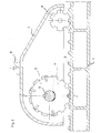
- Fig. 2 shows a kcm p lette cutting device as a variant with gear-like support wheels.
- a support wheel 4 shown partly in section, rolls on the base between the longitudinal ribs 2 of the profile 1 and thus holds a milling cutter blade 5 at a precise distance from the base surface of the profile 1, because the diameter of the support wheel is somewhat larger than that of the cutter blade 5.
- Any number of milling cutters are keyed onto a shaft 6, while the outer support wheels 4 are loosely rotatably mounted on the shaft 6.
- the housing 7 connects the
- Milling cutter shaft with a front support wheel 8 for the purpose of better guidance of the device. Either by hand or when using a rigid guide frame by means of spring force, the device is loaded at 9 for pressing onto the profile to be machined.
- These pedestals serve the same purpose as the supporting wheel 4 in Figure 2, but here the profile to slide the two lateral pedestals 10 above the upper edges of the longitudinal ribs 2 1.
- the diameter of the cutter blades 5 ' is in this case the depth of g to be cut Querriffelun greater than the height of the trestles.
- the front guidance is accomplished, for example, by a sliding shoe 11.
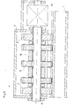
- FIG. 4 shows a cross section through the cutting device according to FIG. 3 with the sliding support blocks 10.
- any number of milling cutters 5 are wedged, which are kept at a distance by spacer bushings 12.
- pedestals 10 are provided which slide across the surface of longitudinal ribs. 2
- a drive 13 of the shaft 6 is electrical or otherwise and is on the housing. attached.
- FIG. 5 shows the cutting device according to FIG. 2 in cross section.
- the two outside support wheels 4 run loosely on the shaft 6 and keep the distance to the surface. Otherwise, the design is as described in FIG. 4.
Landscapes
- Engineering & Computer Science (AREA)
- Mechanical Engineering (AREA)
- Automation & Control Theory (AREA)
- Milling Processes (AREA)
Applications Claiming Priority (2)
| Application Number | Priority Date | Filing Date | Title |
|---|---|---|---|
| AT0436583A AT381265B (de) | 1983-12-15 | 1983-12-15 | Verfahren und vorrichtung zur herstellung einer querriffelung auf laengsgerippten oberflaechen |
| AT4365/83 | 1983-12-15 |
Publications (3)
| Publication Number | Publication Date |
|---|---|
| EP0146110A2 true EP0146110A2 (fr) | 1985-06-26 |
| EP0146110A3 EP0146110A3 (en) | 1987-08-05 |
| EP0146110B1 EP0146110B1 (fr) | 1989-10-11 |
Family
ID=3563044
Family Applications (1)
| Application Number | Title | Priority Date | Filing Date |
|---|---|---|---|
| EP19840115202 Expired EP0146110B1 (fr) | 1983-12-15 | 1984-12-12 | Dispositif d' usinage des rainures transversales dans des plaques de fond rainurées longitudinales etc. |
Country Status (3)
| Country | Link |
|---|---|
| EP (1) | EP0146110B1 (fr) |
| AT (1) | AT381265B (fr) |
| DE (1) | DE3480061D1 (fr) |
Cited By (2)
| Publication number | Priority date | Publication date | Assignee | Title |
|---|---|---|---|---|
| EP0709156A1 (fr) * | 1994-10-28 | 1996-05-01 | Black & Decker Inc. | Scie sauteuse |
| US6626617B2 (en) * | 2000-02-02 | 2003-09-30 | Reich Spezialmaschinen Gmbh | Process for the milling of a groove into a board-like workpiece as well as processing machine for carrying out the process |
Family Cites Families (8)
| Publication number | Priority date | Publication date | Assignee | Title |
|---|---|---|---|---|
| CH315529A (de) * | 1953-10-28 | 1956-08-31 | Denes Zoltan | Verfahren zum Ausschneiden von Gesteinsblöcken aus dem gewachsenen Fels in einer Steingrube und Anlage zur Durchführung dieses Verfahrens |
| US3011530A (en) * | 1959-07-13 | 1961-12-05 | Lamb Ellard | Guide for portable saw |
| FR1365245A (fr) * | 1963-08-07 | 1964-06-26 | Mohr & Federhaff Ag | Fraiseuse transportable à portique |
| FR2256807A1 (en) * | 1974-01-07 | 1975-08-01 | Merzeau Jean Alain | Woodworking tool forming slots - has multiple sets of toothed rotary cutters and spacers altered to vary spacing of slots |
| DE2552484A1 (de) * | 1975-11-22 | 1977-05-26 | Helmut Meyer | Maschine fuer die spanende bearbeitung von flaechen |
| US4188934A (en) * | 1978-10-20 | 1980-02-19 | Cushion Cut, Inc. | Step safety groover apparatus |
| GB2032304B (en) * | 1978-10-28 | 1982-10-06 | Atlas Architectural Fittings L | Manufacture of barrel bolt |
| DE3145913C1 (de) * | 1981-11-19 | 1983-10-06 | Fritz Fleissner | Fraeswerkzeug fuer ein von Hand gefuehrtes Fraesgeraet,zum Fraesen einer Innenschulter an einer Schmucksteinfassung |
-
1983
- 1983-12-15 AT AT0436583A patent/AT381265B/de not_active IP Right Cessation
-
1984
- 1984-12-12 EP EP19840115202 patent/EP0146110B1/fr not_active Expired
- 1984-12-12 DE DE8484115202T patent/DE3480061D1/de not_active Expired
Cited By (2)
| Publication number | Priority date | Publication date | Assignee | Title |
|---|---|---|---|---|
| EP0709156A1 (fr) * | 1994-10-28 | 1996-05-01 | Black & Decker Inc. | Scie sauteuse |
| US6626617B2 (en) * | 2000-02-02 | 2003-09-30 | Reich Spezialmaschinen Gmbh | Process for the milling of a groove into a board-like workpiece as well as processing machine for carrying out the process |
Also Published As
| Publication number | Publication date |
|---|---|
| EP0146110A3 (en) | 1987-08-05 |
| DE3480061D1 (en) | 1989-11-16 |
| EP0146110B1 (fr) | 1989-10-11 |
| AT381265B (de) | 1986-09-25 |
| ATA436583A (de) | 1986-02-15 |
Similar Documents
| Publication | Publication Date | Title |
|---|---|---|
| DE69314287T2 (de) | Hängebahnsystem mit Traktion | |
| DE102018110513A1 (de) | Sägevorrichtung | |
| DE3151835A1 (de) | Zahnstangen-lenkgetriebe | |
| DE3015227C2 (de) | Gleisverfahrbare Maschine zum Abtragen von Unregelmäßigkeiten an der Schienenkopfoberseite eines verlegten Gleises | |
| EP0185850A2 (fr) | Tour à roues, en fosse, pour le reprofilage des contours de bandage d'essieux ferroviaires | |
| DE2525227B2 (de) | Vorrichtung zum Schleifen von Eisenbahnschienen | |
| DE3047565A1 (en) | Wooden pole for power lines or the like,and machine for producing same | |
| EP1862232A1 (fr) | Profilé extrudé, en particulier profil de sol | |
| EP0146110A2 (fr) | Dispositif d' usinage des rainures transversales dans des plaques de fond rainurées longitudinales etc. | |
| DE2343471C2 (de) | Verfahren und Einrichtung zum Herstellen von langen Spannbetonelementen | |
| DE3004965C2 (fr) | ||
| DE2732620A1 (de) | Verfahren und vorrichtung zum schleifen, fraesen und polieren von werkstuecken, wie granit, marmor, baustoffe oder aehnlich sproede materialien | |
| DE102005063327A1 (de) | Vorrichtung zum Trennen eines plastischen Tonstranges, mit einer allseitig wirksamen Kerbvorrichtung | |
| DE2727287C2 (de) | Vorrichtung zum Biegen profilierter Platten | |
| DE2748709A1 (de) | Walzenstaender | |
| DE2918425C2 (de) | Verfahren zur höhenausgleichenden Unterstützung einer Gleissicherung während des Einschiebens eines Bauwerks unter Gleisen und Vorrichtung zur Durchführung des Verfahrens | |
| DE2519350A1 (de) | Vorrichtung fuer holzfraesmaschinen | |
| DE2548894A1 (de) | Verfahren und vorrichtung zum herstellen von erzeugnissen aus porenleichtbeton | |
| DE19624584C1 (de) | Verfahren und Vorrichtung zum Zerschneiden eines Tonstrangs | |
| DE926424C (de) | Verfahren und Vorrichtung zur Herstellung von Ausschnitten in Metallstreifen oder -baendern | |
| DE2543990B2 (de) | Horizontalspaltmaschine | |
| DE3305666A1 (de) | Kontinuierliche kalibriermaschine fuer granitplatten | |
| DE2460741C3 (de) | Vorrichtung zum Ausrichten von zu besäumenden Brettern | |
| AT370321B (de) | Vorrichtung zur bearbeitung von skiern mit einer laufflaeche | |
| DE2646483A1 (de) | Profilierrolle |
Legal Events
| Date | Code | Title | Description |
|---|---|---|---|
| PUAI | Public reference made under article 153(3) epc to a published international application that has entered the european phase |
Free format text: ORIGINAL CODE: 0009012 |
|
| AK | Designated contracting states |
Designated state(s): CH DE FR LI NL SE |
|
| RTI1 | Title (correction) | ||
| RAP1 | Party data changed (applicant data changed or rights of an application transferred) |
Owner name: AUSTRIA METALL AKTIENGESELLSCHAFT |
|
| PUAL | Search report despatched |
Free format text: ORIGINAL CODE: 0009013 |
|
| AK | Designated contracting states |
Kind code of ref document: A3 Designated state(s): CH DE FR LI NL SE |
|
| 17P | Request for examination filed |
Effective date: 19871211 |
|
| 17Q | First examination report despatched |
Effective date: 19880601 |
|
| GRAA | (expected) grant |
Free format text: ORIGINAL CODE: 0009210 |
|
| AK | Designated contracting states |
Kind code of ref document: B1 Designated state(s): CH DE FR LI NL SE |
|
| REF | Corresponds to: |
Ref document number: 3480061 Country of ref document: DE Date of ref document: 19891116 |
|
| ET | Fr: translation filed | ||
| PLBE | No opposition filed within time limit |
Free format text: ORIGINAL CODE: 0009261 |
|
| STAA | Information on the status of an ep patent application or granted ep patent |
Free format text: STATUS: NO OPPOSITION FILED WITHIN TIME LIMIT |
|
| 26N | No opposition filed | ||
| PGFP | Annual fee paid to national office [announced via postgrant information from national office to epo] |
Ref country code: SE Payment date: 19901221 Year of fee payment: 7 |
|
| PGFP | Annual fee paid to national office [announced via postgrant information from national office to epo] |
Ref country code: NL Payment date: 19901231 Year of fee payment: 7 Ref country code: FR Payment date: 19901231 Year of fee payment: 7 |
|
| PGFP | Annual fee paid to national office [announced via postgrant information from national office to epo] |
Ref country code: DE Payment date: 19910124 Year of fee payment: 7 |
|
| PGFP | Annual fee paid to national office [announced via postgrant information from national office to epo] |
Ref country code: CH Payment date: 19910227 Year of fee payment: 7 |
|
| PG25 | Lapsed in a contracting state [announced via postgrant information from national office to epo] |
Ref country code: SE Effective date: 19911213 |
|
| PG25 | Lapsed in a contracting state [announced via postgrant information from national office to epo] |
Ref country code: LI Effective date: 19911231 Ref country code: CH Effective date: 19911231 |
|
| PG25 | Lapsed in a contracting state [announced via postgrant information from national office to epo] |
Ref country code: NL Effective date: 19920701 |
|
| NLV4 | Nl: lapsed or anulled due to non-payment of the annual fee | ||
| PG25 | Lapsed in a contracting state [announced via postgrant information from national office to epo] |
Ref country code: FR Effective date: 19920831 |
|
| REG | Reference to a national code |
Ref country code: CH Ref legal event code: PL |
|
| PG25 | Lapsed in a contracting state [announced via postgrant information from national office to epo] |
Ref country code: DE Effective date: 19920901 |
|
| REG | Reference to a national code |
Ref country code: FR Ref legal event code: ST |
|
| EUG | Se: european patent has lapsed |
Ref document number: 84115202.8 Effective date: 19920704 |