EP0146182A1 - Gerät zur Untersuchung von Medien mittels Ultraschall-Echographie - Google Patents
Gerät zur Untersuchung von Medien mittels Ultraschall-Echographie Download PDFInfo
- Publication number
- EP0146182A1 EP0146182A1 EP84201806A EP84201806A EP0146182A1 EP 0146182 A1 EP0146182 A1 EP 0146182A1 EP 84201806 A EP84201806 A EP 84201806A EP 84201806 A EP84201806 A EP 84201806A EP 0146182 A1 EP0146182 A1 EP 0146182A1
- Authority
- EP
- European Patent Office
- Prior art keywords
- circuit
- output
- digital
- input
- instantaneous
- Prior art date
- Legal status (The legal status is an assumption and is not a legal conclusion. Google has not performed a legal analysis and makes no representation as to the accuracy of the status listed.)
- Granted
Links
- 238000012937 correction Methods 0.000 claims abstract description 29
- 238000002604 ultrasonography Methods 0.000 claims abstract description 28
- 238000012545 processing Methods 0.000 claims abstract description 14
- 238000002592 echocardiography Methods 0.000 claims description 8
- 230000006870 function Effects 0.000 claims description 5
- 230000000694 effects Effects 0.000 claims description 3
- 230000000295 complement effect Effects 0.000 claims description 2
- 230000005540 biological transmission Effects 0.000 abstract 1
- 230000036962 time dependent Effects 0.000 abstract 1
- 238000001914 filtration Methods 0.000 description 9
- 230000000875 corresponding effect Effects 0.000 description 3
- 230000003111 delayed effect Effects 0.000 description 3
- 230000004044 response Effects 0.000 description 3
- 239000000523 sample Substances 0.000 description 3
- 238000005070 sampling Methods 0.000 description 3
- 230000009471 action Effects 0.000 description 2
- 238000006073 displacement reaction Methods 0.000 description 2
- 238000001228 spectrum Methods 0.000 description 2
- 230000007704 transition Effects 0.000 description 2
- 239000003990 capacitor Substances 0.000 description 1
- 230000002596 correlated effect Effects 0.000 description 1
- 238000011161 development Methods 0.000 description 1
- 230000018109 developmental process Effects 0.000 description 1
- 238000010586 diagram Methods 0.000 description 1
- 238000011156 evaluation Methods 0.000 description 1
- 230000003993 interaction Effects 0.000 description 1
- 230000001902 propagating effect Effects 0.000 description 1
- 230000009467 reduction Effects 0.000 description 1
- 238000011160 research Methods 0.000 description 1
- 238000000926 separation method Methods 0.000 description 1
- 230000002123 temporal effect Effects 0.000 description 1
- 238000012360 testing method Methods 0.000 description 1
- 230000001960 triggered effect Effects 0.000 description 1
Images

Classifications
-
- G—PHYSICS
- G01—MEASURING; TESTING
- G01S—RADIO DIRECTION-FINDING; RADIO NAVIGATION; DETERMINING DISTANCE OR VELOCITY BY USE OF RADIO WAVES; LOCATING OR PRESENCE-DETECTING BY USE OF THE REFLECTION OR RERADIATION OF RADIO WAVES; ANALOGOUS ARRANGEMENTS USING OTHER WAVES
- G01S7/00—Details of systems according to groups G01S13/00, G01S15/00, G01S17/00
- G01S7/52—Details of systems according to groups G01S13/00, G01S15/00, G01S17/00 of systems according to group G01S15/00
- G01S7/52017—Details of systems according to groups G01S13/00, G01S15/00, G01S17/00 of systems according to group G01S15/00 particularly adapted to short-range imaging
- G01S7/52023—Details of receivers
- G01S7/52025—Details of receivers for pulse systems
-
- G—PHYSICS
- G01—MEASURING; TESTING
- G01S—RADIO DIRECTION-FINDING; RADIO NAVIGATION; DETERMINING DISTANCE OR VELOCITY BY USE OF RADIO WAVES; LOCATING OR PRESENCE-DETECTING BY USE OF THE REFLECTION OR RERADIATION OF RADIO WAVES; ANALOGOUS ARRANGEMENTS USING OTHER WAVES
- G01S15/00—Systems using the reflection or reradiation of acoustic waves, e.g. sonar systems
- G01S15/88—Sonar systems specially adapted for specific applications
- G01S15/89—Sonar systems specially adapted for specific applications for mapping or imaging
- G01S15/8906—Short-range imaging systems; Acoustic microscope systems using pulse-echo techniques
- G01S15/895—Short-range imaging systems; Acoustic microscope systems using pulse-echo techniques characterised by the transmitted frequency spectrum
- G01S15/8954—Short-range imaging systems; Acoustic microscope systems using pulse-echo techniques characterised by the transmitted frequency spectrum using a broad-band spectrum
-
- G—PHYSICS
- G01—MEASURING; TESTING
- G01S—RADIO DIRECTION-FINDING; RADIO NAVIGATION; DETERMINING DISTANCE OR VELOCITY BY USE OF RADIO WAVES; LOCATING OR PRESENCE-DETECTING BY USE OF THE REFLECTION OR RERADIATION OF RADIO WAVES; ANALOGOUS ARRANGEMENTS USING OTHER WAVES
- G01S7/00—Details of systems according to groups G01S13/00, G01S15/00, G01S17/00
- G01S7/52—Details of systems according to groups G01S13/00, G01S15/00, G01S17/00 of systems according to group G01S15/00
- G01S7/52017—Details of systems according to groups G01S13/00, G01S15/00, G01S17/00 of systems according to group G01S15/00 particularly adapted to short-range imaging
- G01S7/52023—Details of receivers
- G01S7/52036—Details of receivers using analysis of echo signal for target characterisation
-
- G—PHYSICS
- G01—MEASURING; TESTING
- G01S—RADIO DIRECTION-FINDING; RADIO NAVIGATION; DETERMINING DISTANCE OR VELOCITY BY USE OF RADIO WAVES; LOCATING OR PRESENCE-DETECTING BY USE OF THE REFLECTION OR RERADIATION OF RADIO WAVES; ANALOGOUS ARRANGEMENTS USING OTHER WAVES
- G01S7/00—Details of systems according to groups G01S13/00, G01S15/00, G01S17/00
- G01S7/52—Details of systems according to groups G01S13/00, G01S15/00, G01S17/00 of systems according to group G01S15/00
- G01S7/52017—Details of systems according to groups G01S13/00, G01S15/00, G01S17/00 of systems according to group G01S15/00 particularly adapted to short-range imaging
- G01S7/5205—Means for monitoring or calibrating
Definitions
- the present invention relates to an apparatus for examining media by ultrasound ultrasound, and finds an essential application in the exploration of biological tissues.
- ultrasonic signals are emitted in the direction of the region to be explored and are then reflected either mainly by the multiple diffusing centers of which said region is made up or also by the transition surfaces between successive media of different acoustic impedances.
- the echoes thus formed are converted into electrical signals in a reception stage which ensures appropriate processing of these signals, in particular a correction of the attenuation of the ultrasonic waves as a function of the distance they have traveled in the environments explored.
- a scanning apparatus of this type is disclosed in US Patent No. granted on 8 8 4057049 November 1977 to name the company transferee National Research Develop- ment Corporation, London, England.
- electrical signals are emitted by a generator 1 to a transducer 2 which converts them into ultrasonic waves of determined spectrum propagating in the region to be explored.
- the echoes corresponding to the obstacles formed by the scattering centers encountered or the transition surfaces between distinct media are again converted by the transducer into electrical signals which are supplied to an amplifier 4, then to a display device 7 after correction. of the ultrasonic attenuation as a function of time.
- the object of the invention is to propose a device falling into the same category as that described above, that is to say whose operation is based on establishing a correlation between the frequency of the reception signal and its amplitude. , but using this principle in a new way.
- the invention relates to an apparatus for exploring media by ultrasound echography comprising at least one ultrasonic transducer associated with a stage for transmitting electrical signals converted by the transducer into acoustic waves and with a stage for receiving and processing ultrasonic echoes appearing as a result of the reflection of these waves on the obstacles encountered in their direction of propagation, this reception and processing stage itself essentially comprising an amplifier, a gain correction circuit as a function of time and a circuit operating the results of the ultrasound examination, characterized in that the reception and processing stage also comprises, at the output of the assembly constituted by the amplifier and the gain correction circuit, means for determining the instantaneous frequency and instantaneous energy of this ultrasound signal, means of weighting the instantaneous frequency by the ener instantaneous gie, and diffraction correction means.
- the structure thus defined makes it possible, in the various embodiments envisaged below, to obtain, by virtue of the establishment of an original frequency-energy correlation, a reduction in the variance affecting the frequency of the reception signals of the ultrasound scanners. ultrasonic.
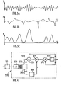
- the ultrasound signal received results from the interference of a multitude of echoes returned by the obstacles encountered, or scattering center.
- the interference nature of this received ultrasound signal is the cause of local variations in the instantaneous frequency ( Figure 1b) of this signal.
- Figure 1c the existence of modulation dips whose temporal position is linked to these local variations of the instantaneous frequency, and the invention will exploit the correlation between these energy dips and these variations of frequency, in order to have a more reliable estimate of this frequency.
- the proposed apparatus therefore comprises, in the example described in FIG. 2, a single probe constituting the support of an ultrasonic transducer 10 and making it possible to obtain type A ultrasound scans.
- the invention is also applicable if we no longer explore a line but an entire planar section of a medium, either using a manual displacement probe or a so-called sectoral angular mechanical displacement probe, associated with a radar type display screen, either using a linear array of ultrasonic transducers defining a certain number of exploration directions and associated with a switching circuit of the stage for receiving and processing echoes successively on each transducer or group of determined transducers, or again using a bar of transducers called sectoral electronic scanning, also associated with a switching circuit as well as with a network of delay lines or phase shifters.
- the transducer 10 is associated on the one hand with an emission stage 20 intended to allow the repeated emission of acoustic waves by the transducer in any direction through the medium to be examined and on the other hand to a reception and processing stage 30.
- This stage 30 is intended to allow the reception and the processing of the ultrasonic echoes received by the transducer 10 and corresponding to the obstacles encountered in their direction of propagation by acoustic waves.
- Said obstacles can either be separation surfaces between successive environments of different acoustic impedances, or the numerous diffusing centers that the explored environment can contain. We will not be interested here in the echoes of great amplitude which materialize the borders between environments but only in the action of the diffusing centers, by limiting useful exploration to an area between two of these borders.
- the reception and processing stage 30 comprises, quite conventionally, a variable gain amplifier 40, a gain compensation circuit 50 ensuring the control of the gain of this amplifier, and, in this case, a device display 60 which displays the signals passing through the stage 30 in the form of a type A ultrasound, on an axis corresponding to the main direction of propagation of the transducer 10.
- the stage 30 also comprises, in accordance with the invention, between circuits 50 and 60, a stage 70 for demodulation and filtering of the echographic signal, then a diffraction correction stage.
- the demodulation and filtering stage 70 itself comprises two parallel channels 110 and 210: the first of these channels comprises in series a circuit 120 for determining the instantaneous frequency of the ultrasound signal (such an eircuit appears for example in the catalog from the company RCA under the reference CA 3089 E), a multiplier 130 and a first low-pass filter 140 whose output is sent to a first input of a divider 90, while the second channel comprises in series a circuit 220 of determination of the instantaneous energy of the ultrasound signal (such a circuit appears for example in the catalog of the Motorola company under the reference MC 1496) and a second low-pass filter 240 whose output is sent to the second input of the divider 90 (filters 140 and 240 are identical).
- the output of circuit 220 is also sent to the second input of the multiplier 130 of the first channel (this circuit 130 can for example be circuit MC 1494 from the Motorola catalog).
- this first embodiment of the invention is as follows. As the ultrasound signal has undergone the action of the gain compensation circuit, its average energy is constant over time, but its instantaneous energy however presents, compared to this average value, local deviations which a more detailed study revealed that '' they were correlated with the local deviations of the instantaneous frequency (they indicate outliers, as was specified above in connection with Figures 1a to 1c): at low energy, the variance on the value of the frequency instantaneous is large, while at high energy, this value is closer to its expected value. From this observation results the decision, in accordance with the invention and as indicated in FIG.
- This diffraction correction stage here comprises an analog-digital converter 81 with m digital outputs sent to a digital memory 82, for example a programmable read only memory (in English, "programmable read-only memory”, or PROM memory).
- This memory also receives the n digital outputs of a counter 83 controlled by a clock circuit 84, itself triggered by the clock of the emission stage 20.
- the diffraction correction stage 80 is necessary in the case of an ultrasound system with non-focusing transducer and even more in the case of a focusing transducer, to ensure compensation for the diffraction effect which occurs due to the dimensions of the transducer, which are not infinitely small, and which distorts the indications provided by the stage 70 of demodulation and filtering.
- the responses thus obtained are therefore used to enter into the memory 82 the diffraction correction values.
- the values thus delivered by the memory in response to one of the m frequency values and one of the n journey time values can be, for example, either a coefficient by which the frequency value to be corrected must be multiplied (a multiplier must then be provided at the output of memory 82), or a deviation whose algebraic value must be added to the frequency value to be corrected (a summator is then provided at the output of memory 82), or the very value of the frequency corrected; these variants are equivalent, in view of the result obtained, and, of course, not limiting.
- the output of the diffraction correction stage 80 whatever that of the variants considered above, is effected by means of a digital-analog converter 85 which is connected to the input of the display device 60.
- stage 30 there may be provided between the frequency and the instantaneous energy an interaction other than linear, for example by inserting just at the output of the instantaneous energy determination circuit 220 a non-linear circuit, such as a threshold circuit, authorizing the passage of the instantaneous energy signal only if the value of the latter reaches a determined threshold.
- a non-linear circuit such as a threshold circuit
- the apparatus according to the invention comprises the same elements as those represented in FIG. 2, with the exception of the stage of demodulation and filtering of the ultrasound signal and the stage of correction of diffraction, which this time bear the references 470 and 480 by analogy with those of FIG. 2.
- This modified demodulation and filtering stage 470 now comprises (see FIG. 3) an analog-digital converter 471 whose outputs are connected to the inputs of a digital circuit 472 for calculating the instantaneous frequency and calculating the instantaneous energy at successive sampling instants.
- the frequency and energy values thus calculated periodically are available at the output of circuit 472 on two channels 473 and 483 in parallel.
- the first channel 473 successively comprises a numerically controlled multiplier 475, the first input of which is therefore connected to the frequency output of the calculation circuit 472, and an adder 476, the output of which is connected to the diffraction correction stage 480 (similar to the stage 80 previously described, except that its input analog-digital converter 81 is no longer necessary, the previous stage now already providing information in digital form).
- f c (t N-1 ) and f c (t N ) the values of the instantaneous frequency at the sampling instants t N-1 and tN after weighting of the latter by the energy and f (t N-1 ) and f (tN) these values before weighting
- the expression of f c (t N ) is, according to the diagram adopted in FIG. 3, given by: The tests carried out by the applicant have shown that an effective weighting is obtained for a coefficient a equal to e / e + 1 (where e (t) represents the instantaneous energy).
- Expression (2) can also be put in the equivalent form: or :
- This expression (3) corresponds to a third embodiment of the apparatus according to the invention in which only the demodulation and filtering stage differs from the embodiments already described. Only this modified stage, referenced 570, is therefore shown in FIG. 4.
- This demodulation and filtering stage 570 comprises an analog-digital converter 571 the outputs of which are connected as before to the inputs of a digital circuit 572 for calculating the instantaneous frequency and the instantaneous energy (at successive sampling instants) .
- the frequency and energy values calculated in this circuit are available on two channels 573 and 583 in parallel, the first of which successively comprises a subtractor 574, a multiplier 575, an adder 576 and a delay circuit 577, and the second of which contains a PROM type 584 read only memory.
- the subtractor 574 receives on the one hand the frequency output of the calculation circuit 572 and on the other hand the output, delayed in the circuit 577, of the adder 576 and.
- of the multiplier 575 is sent to the adder 576, which also receives its own input delayed output in circuit 577 and delivers the signal f c ( t N ) equal to f c (t N-1 ) + a [f (t N ) - f c (t N-1 )].
- This signal f (t) is delayed in the circuit 577 and then constitutes on the one hand the signal which is returned to the adder 576 and to the subtractor 574 and on the other hand the output signal from stage 570, sent towards the entrance to the diffraction correction stage 580; this stage 580 is identical to stage 480, itself similar to stage 80, apart from the absence of the input analog-digital converter 81.
- the present invention is not limited to the embodiments described above and shown, from which variants can still be proposed without thereby departing from the scope of the invention.
- the invention consists, in broad outline, in modulating the filtering of information in frequency by information in energy.
- the embodiment of the invention can therefore also be ensured by an RC circuit in series with the instantaneous frequency channel, the instantaneous energy channel being connected to the terminal for adjusting the adjustable resistance R and the output of the circuit being taken across the capacitor C.
Landscapes
- Engineering & Computer Science (AREA)
- Physics & Mathematics (AREA)
- Radar, Positioning & Navigation (AREA)
- Remote Sensing (AREA)
- Computer Networks & Wireless Communication (AREA)
- General Physics & Mathematics (AREA)
- Acoustics & Sound (AREA)
- Ultra Sonic Daignosis Equipment (AREA)
- Investigating Or Analyzing Materials By The Use Of Ultrasonic Waves (AREA)
- Measurement Of Velocity Or Position Using Acoustic Or Ultrasonic Waves (AREA)
Applications Claiming Priority (2)
| Application Number | Priority Date | Filing Date | Title |
|---|---|---|---|
| FR8320042A FR2556844B1 (fr) | 1983-12-14 | 1983-12-14 | Appareil d'examen de milieux par echographie ultrasonore |
| FR8320042 | 1983-12-14 |
Publications (2)
| Publication Number | Publication Date |
|---|---|
| EP0146182A1 true EP0146182A1 (de) | 1985-06-26 |
| EP0146182B1 EP0146182B1 (de) | 1989-08-09 |
Family
ID=9295179
Family Applications (1)
| Application Number | Title | Priority Date | Filing Date |
|---|---|---|---|
| EP84201806A Expired EP0146182B1 (de) | 1983-12-14 | 1984-12-05 | Gerät zur Untersuchung von Medien mittels Ultraschall-Echographie |
Country Status (10)
| Country | Link |
|---|---|
| US (1) | US4576046A (de) |
| EP (1) | EP0146182B1 (de) |
| JP (1) | JPS60144660A (de) |
| AU (1) | AU571398B2 (de) |
| BR (1) | BR8406321A (de) |
| CA (1) | CA1230406A (de) |
| DE (1) | DE3479346D1 (de) |
| ES (1) | ES8604016A1 (de) |
| FR (1) | FR2556844B1 (de) |
| IL (1) | IL73801A (de) |
Cited By (3)
| Publication number | Priority date | Publication date | Assignee | Title |
|---|---|---|---|---|
| EP0206290A1 (de) * | 1985-06-20 | 1986-12-30 | Kontron Instruments Holding N.V. | Verfahren und Vorrichtung zur Erzeugung von Abbildungen |
| EP0361606A1 (de) * | 1988-09-30 | 1990-04-04 | Laboratoires D'electronique Philips | Gerät zur Verarbeitung eines echographischen Signals |
| US5187687A (en) * | 1985-06-20 | 1993-02-16 | Kontron Instruments Holding N.V. | Production of images |
Families Citing this family (3)
| Publication number | Priority date | Publication date | Assignee | Title |
|---|---|---|---|---|
| FR2579763B1 (fr) * | 1985-03-29 | 1987-04-10 | Labo Electronique Physique | Procede et appareil d'exploration de milieux par echographie ultrasonore |
| FR2593698A1 (fr) * | 1986-01-31 | 1987-08-07 | Labo Electronique Physique | Appareil d'examen de milieux en mouvement par echographie ultrasonore |
| WO2007051075A1 (en) * | 2005-10-28 | 2007-05-03 | Brigham And Women's Hospital, Inc. | Ultrasound imaging |
Citations (7)
| Publication number | Priority date | Publication date | Assignee | Title |
|---|---|---|---|---|
| GB2023830A (en) * | 1978-06-22 | 1980-01-03 | Philips Nv | Determining the internal structure of a body by means of acoustic beams |
| US4197750A (en) * | 1977-05-31 | 1980-04-15 | Siemens Aktiengesellschaft | Ultrasonic imaging apparatus operating according to the impulse-echo method |
| US4202215A (en) * | 1978-10-26 | 1980-05-13 | Kurt Orban Company, Inc. | Sonic pulse-echo method and apparatus for determining attenuation coefficients |
| US4409838A (en) * | 1980-07-02 | 1983-10-18 | U.S. Philips Corporation | Ultrasonic diagnostic device |
| EP0100234A2 (de) * | 1982-07-26 | 1984-02-08 | Fujitsu Limited | Messung der charakteristischen Werte eines Mediums mittels Ultraschall |
| EP0106409A1 (de) * | 1982-10-13 | 1984-04-25 | Laboratoires D'electronique Et De Physique Appliquee L.E.P. | Gerät zum Untersuchen von Medien mittels Ultraschallechographie |
| EP0107172A2 (de) * | 1982-10-27 | 1984-05-02 | General Electric Company | Ultraschall-Abbildungssystem mit einem durch den Bedienungsmann geregelten Filter zur Dämpfungskompensierung des reflektierten Signals |
Family Cites Families (6)
| Publication number | Priority date | Publication date | Assignee | Title |
|---|---|---|---|---|
| GB1522608A (en) * | 1974-10-11 | 1978-08-23 | Nat Res Dev | Apparatus for and method of pulse-echo examination |
| US4016750B1 (en) * | 1975-11-06 | 1994-04-05 | Stanford Research Inst | Ultrasonic imaging method and apparatus |
| SE425996B (sv) * | 1981-12-22 | 1982-11-29 | Salomonsson Goeran | Sett och anordning for alstring av korta ultraljudsekopulser |
| JPS58113747A (ja) * | 1981-12-26 | 1983-07-06 | Toshiba Corp | 超音波探傷装置 |
| US4512196A (en) * | 1983-09-30 | 1985-04-23 | North American Philips Corporation | Ultrasound imaging with FM detection |
| FR2554238B1 (fr) * | 1983-10-28 | 1986-02-28 | Labo Electronique Physique | Appareil d'exploration de milieux par echographie ultrasonore |
-
1983
- 1983-12-14 FR FR8320042A patent/FR2556844B1/fr not_active Expired
-
1984
- 1984-12-05 EP EP84201806A patent/EP0146182B1/de not_active Expired
- 1984-12-05 DE DE8484201806T patent/DE3479346D1/de not_active Expired
- 1984-12-11 ES ES538476A patent/ES8604016A1/es not_active Expired
- 1984-12-11 BR BR8406321A patent/BR8406321A/pt unknown
- 1984-12-11 IL IL73801A patent/IL73801A/xx not_active IP Right Cessation
- 1984-12-11 US US06/680,415 patent/US4576046A/en not_active Expired - Fee Related
- 1984-12-11 JP JP59260111A patent/JPS60144660A/ja active Pending
- 1984-12-12 AU AU36559/84A patent/AU571398B2/en not_active Expired - Fee Related
- 1984-12-13 CA CA000470050A patent/CA1230406A/en not_active Expired
Patent Citations (7)
| Publication number | Priority date | Publication date | Assignee | Title |
|---|---|---|---|---|
| US4197750A (en) * | 1977-05-31 | 1980-04-15 | Siemens Aktiengesellschaft | Ultrasonic imaging apparatus operating according to the impulse-echo method |
| GB2023830A (en) * | 1978-06-22 | 1980-01-03 | Philips Nv | Determining the internal structure of a body by means of acoustic beams |
| US4202215A (en) * | 1978-10-26 | 1980-05-13 | Kurt Orban Company, Inc. | Sonic pulse-echo method and apparatus for determining attenuation coefficients |
| US4409838A (en) * | 1980-07-02 | 1983-10-18 | U.S. Philips Corporation | Ultrasonic diagnostic device |
| EP0100234A2 (de) * | 1982-07-26 | 1984-02-08 | Fujitsu Limited | Messung der charakteristischen Werte eines Mediums mittels Ultraschall |
| EP0106409A1 (de) * | 1982-10-13 | 1984-04-25 | Laboratoires D'electronique Et De Physique Appliquee L.E.P. | Gerät zum Untersuchen von Medien mittels Ultraschallechographie |
| EP0107172A2 (de) * | 1982-10-27 | 1984-05-02 | General Electric Company | Ultraschall-Abbildungssystem mit einem durch den Bedienungsmann geregelten Filter zur Dämpfungskompensierung des reflektierten Signals |
Non-Patent Citations (2)
| Title |
|---|
| IBM JOURNAL OF RESEARCH AND DEVELOPMENT, volume 25, no. 1, janvier 1981, pages 71-82, New York, US; K.M. PAN et al. "Tomographic reconstruction of ultrasonic attenuation with correction for refractive errors" * |
| IEEE TRANSACTIONS ON SONICS AND ULTRASONICS, vol. SU-30, no. 1, janvier 1983, pages 26-36, New York, US; M. O'DONNELL "Quantitative volume backscatter imaging" * |
Cited By (4)
| Publication number | Priority date | Publication date | Assignee | Title |
|---|---|---|---|---|
| EP0206290A1 (de) * | 1985-06-20 | 1986-12-30 | Kontron Instruments Holding N.V. | Verfahren und Vorrichtung zur Erzeugung von Abbildungen |
| US5187687A (en) * | 1985-06-20 | 1993-02-16 | Kontron Instruments Holding N.V. | Production of images |
| EP0361606A1 (de) * | 1988-09-30 | 1990-04-04 | Laboratoires D'electronique Philips | Gerät zur Verarbeitung eines echographischen Signals |
| FR2637400A1 (fr) * | 1988-09-30 | 1990-04-06 | Labo Electronique Physique | Dispositif de traitement ameliore d'un signal echographique |
Also Published As
| Publication number | Publication date |
|---|---|
| ES8604016A1 (es) | 1986-01-16 |
| ES538476A0 (es) | 1986-01-16 |
| FR2556844A1 (fr) | 1985-06-21 |
| FR2556844B1 (fr) | 1987-11-13 |
| US4576046A (en) | 1986-03-18 |
| BR8406321A (pt) | 1985-10-08 |
| JPS60144660A (ja) | 1985-07-31 |
| IL73801A (en) | 1988-11-15 |
| EP0146182B1 (de) | 1989-08-09 |
| AU3655984A (en) | 1985-06-20 |
| DE3479346D1 (en) | 1989-09-14 |
| CA1230406A (en) | 1987-12-15 |
| IL73801A0 (en) | 1985-03-31 |
| AU571398B2 (en) | 1988-04-14 |
Similar Documents
| Publication | Publication Date | Title |
|---|---|---|
| EP0225667B1 (de) | Gerät zur Ultraschallechographie der Bewegung von Körperorganen, insbesondere der Blutströmung oder des Herzens | |
| EP0261736B1 (de) | Vorrichtung zur Untersuchung von ortsveränderlichen Medien mittels Ultraschall-Echographie | |
| EP0077585B1 (de) | Vorrichtung zur Untersuchung von Medien mittels Ultraschallechographie | |
| EP0190805B1 (de) | Gerät zur Untersuchung von Medien mittels Ultraschallechographie | |
| EP0459583B1 (de) | Ultraschallbildgerät mit adaptiver Phasenaberrationskorrektur | |
| EP0140450B1 (de) | Verfahren und Gerät zur Untersuchung von Medien mittels Ultraschall-Echographie | |
| EP0196713B1 (de) | Verfahren und Vorrichtung zur Untersuchung von Medien mittels Ultraschall-Echographie | |
| EP0106409B1 (de) | Gerät zum Untersuchen von Medien mittels Ultraschallechographie | |
| EP0166836B1 (de) | Verfahren zur Charakterisierung der Struktur eines Mediums und Vorrichtung dafür | |
| CH625053A5 (de) | ||
| EP0146182B1 (de) | Gerät zur Untersuchung von Medien mittels Ultraschall-Echographie | |
| FR2652654A1 (fr) | Echographe ultrasonore utilisant un dispositif numerique de formation de voies en reception. | |
| EP0164808A1 (de) | Gerät zur Untersuchung von Medien mittels Ultraschallechographie | |
| EP0106418B1 (de) | Gerät zum Untersuchen von Medien mittels Ultraschallechographie | |
| EP0197582B1 (de) | Verfahren und Vorrichtung zur Untersuchung von Medien mittels Ultraschall-Echographie | |
| EP0159081B1 (de) | Gerät zur Untersuchung von Medien mittels Ultraschall-Echographie | |
| CA1226654A (fr) | Dispositif de discrimination d'echos radar | |
| EP0196714B1 (de) | Verfahren und Vorrichtung zur Untersuchung von Medien mittels Ultraschall-Echographie | |
| EP0520563B1 (de) | Ultraschall-Echographie mit adaptiver Phasenaberrationkorrektur | |
| EP0334442A1 (de) | Echokompensator für Echosignale mit veränderlicher Phase | |
| FR2680250A1 (fr) | Procede et dispositif d'imagerie ultra-sonore d'objets en milieu liquide. | |
| EP0596560A1 (de) | Gerät zur Untersuchung von Medien mittels Ultraschallechographie | |
| EP0036366A1 (de) | System zur Verarbeitung eines durch Fernmessung der Windgeschwindigkeit erhaltenen akustischen Signals | |
| FR2596270A1 (fr) | Appareil d'exploration par echographie ultrasonore de milieux en mouvement et notamment d'ecoulements sanguins ou d'organes tels que le coeur | |
| FR2552550A1 (fr) | Appareil d'exploration de milieux par echographie ultrasonore |
Legal Events
| Date | Code | Title | Description |
|---|---|---|---|
| PUAI | Public reference made under article 153(3) epc to a published international application that has entered the european phase |
Free format text: ORIGINAL CODE: 0009012 |
|
| AK | Designated contracting states |
Designated state(s): BE DE FR GB SE |
|
| 17P | Request for examination filed |
Effective date: 19851220 |
|
| 17Q | First examination report despatched |
Effective date: 19871116 |
|
| GRAA | (expected) grant |
Free format text: ORIGINAL CODE: 0009210 |
|
| AK | Designated contracting states |
Kind code of ref document: B1 Designated state(s): BE DE FR GB SE |
|
| PG25 | Lapsed in a contracting state [announced via postgrant information from national office to epo] |
Ref country code: SE Effective date: 19890809 |
|
| REF | Corresponds to: |
Ref document number: 3479346 Country of ref document: DE Date of ref document: 19890914 |
|
| GBT | Gb: translation of ep patent filed (gb section 77(6)(a)/1977) | ||
| PG25 | Lapsed in a contracting state [announced via postgrant information from national office to epo] |
Ref country code: BE Effective date: 19891231 |
|
| REG | Reference to a national code |
Ref country code: FR Ref legal event code: CD |
|
| PLBE | No opposition filed within time limit |
Free format text: ORIGINAL CODE: 0009261 |
|
| STAA | Information on the status of an ep patent application or granted ep patent |
Free format text: STATUS: NO OPPOSITION FILED WITHIN TIME LIMIT |
|
| BERE | Be: lapsed |
Owner name: PHILIPS' GLOEILAMPENFABRIEKEN N.V. Effective date: 19891231 Owner name: LABORATOIRES D'ELECTRONIQUE ET DE PHYSIQUE APPLIQU Effective date: 19891231 |
|
| 26N | No opposition filed | ||
| PGFP | Annual fee paid to national office [announced via postgrant information from national office to epo] |
Ref country code: GB Payment date: 19941130 Year of fee payment: 11 |
|
| PGFP | Annual fee paid to national office [announced via postgrant information from national office to epo] |
Ref country code: FR Payment date: 19941221 Year of fee payment: 11 |
|
| PGFP | Annual fee paid to national office [announced via postgrant information from national office to epo] |
Ref country code: DE Payment date: 19950222 Year of fee payment: 11 |
|
| PG25 | Lapsed in a contracting state [announced via postgrant information from national office to epo] |
Ref country code: GB Effective date: 19951205 |
|
| REG | Reference to a national code |
Ref country code: FR Ref legal event code: CJ Ref country code: FR Ref legal event code: CD |
|
| GBPC | Gb: european patent ceased through non-payment of renewal fee |
Effective date: 19951205 |
|
| PG25 | Lapsed in a contracting state [announced via postgrant information from national office to epo] |
Ref country code: FR Effective date: 19960830 |
|
| PG25 | Lapsed in a contracting state [announced via postgrant information from national office to epo] |
Ref country code: DE Effective date: 19960903 |
|
| REG | Reference to a national code |
Ref country code: FR Ref legal event code: ST |