EP0146218B1 - Agencement de pédale - Google Patents
Agencement de pédale Download PDFInfo
- Publication number
- EP0146218B1 EP0146218B1 EP84306661A EP84306661A EP0146218B1 EP 0146218 B1 EP0146218 B1 EP 0146218B1 EP 84306661 A EP84306661 A EP 84306661A EP 84306661 A EP84306661 A EP 84306661A EP 0146218 B1 EP0146218 B1 EP 0146218B1
- Authority
- EP
- European Patent Office
- Prior art keywords
- pedal
- shoe
- abutment member
- engagement means
- cycle
- Prior art date
- Legal status (The legal status is an assumption and is not a legal conclusion. Google has not performed a legal analysis and makes no representation as to the accuracy of the status listed.)
- Expired
Links
- 230000002401 inhibitory effect Effects 0.000 claims description 4
- 230000003213 activating effect Effects 0.000 claims description 2
- 230000015572 biosynthetic process Effects 0.000 description 8
- 238000004519 manufacturing process Methods 0.000 description 6
- 230000006378 damage Effects 0.000 description 5
- 239000000463 material Substances 0.000 description 5
- 208000027418 Wounds and injury Diseases 0.000 description 4
- 208000014674 injury Diseases 0.000 description 4
- 230000001351 cycling effect Effects 0.000 description 3
- 238000012423 maintenance Methods 0.000 description 3
- 238000000465 moulding Methods 0.000 description 3
- 210000002105 tongue Anatomy 0.000 description 3
- 238000010276 construction Methods 0.000 description 2
- 230000000694 effects Effects 0.000 description 2
- 229920003023 plastic Polymers 0.000 description 2
- 239000004033 plastic Substances 0.000 description 2
- 208000012661 Dyskinesia Diseases 0.000 description 1
- 239000000853 adhesive Substances 0.000 description 1
- 230000001070 adhesive effect Effects 0.000 description 1
- 230000017531 blood circulation Effects 0.000 description 1
- 210000000988 bone and bone Anatomy 0.000 description 1
- 230000000881 depressing effect Effects 0.000 description 1
- 230000000994 depressogenic effect Effects 0.000 description 1
- 238000000034 method Methods 0.000 description 1
- 230000017311 musculoskeletal movement, spinal reflex action Effects 0.000 description 1
- 238000002360 preparation method Methods 0.000 description 1
- 230000002441 reversible effect Effects 0.000 description 1
Images


Classifications
-
- A—HUMAN NECESSITIES
- A43—FOOTWEAR
- A43B—CHARACTERISTIC FEATURES OF FOOTWEAR; PARTS OF FOOTWEAR
- A43B5/00—Footwear for sporting purposes
- A43B5/14—Shoes for cyclists
-
- B—PERFORMING OPERATIONS; TRANSPORTING
- B62—LAND VEHICLES FOR TRAVELLING OTHERWISE THAN ON RAILS
- B62M—RIDER PROPULSION OF WHEELED VEHICLES OR SLEDGES; POWERED PROPULSION OF SLEDGES OR SINGLE-TRACK CYCLES; TRANSMISSIONS SPECIALLY ADAPTED FOR SUCH VEHICLES
- B62M3/00—Construction of cranks operated by hand or foot
- B62M3/08—Pedals
- B62M3/086—Attachments between shoe and pedal other than toe clips, e.g. cleats
-
- Y—GENERAL TAGGING OF NEW TECHNOLOGICAL DEVELOPMENTS; GENERAL TAGGING OF CROSS-SECTIONAL TECHNOLOGIES SPANNING OVER SEVERAL SECTIONS OF THE IPC; TECHNICAL SUBJECTS COVERED BY FORMER USPC CROSS-REFERENCE ART COLLECTIONS [XRACs] AND DIGESTS
- Y10—TECHNICAL SUBJECTS COVERED BY FORMER USPC
- Y10T—TECHNICAL SUBJECTS COVERED BY FORMER US CLASSIFICATION
- Y10T74/00—Machine element or mechanism
- Y10T74/21—Elements
- Y10T74/2164—Cranks and pedals
- Y10T74/2168—Pedals
- Y10T74/217—Pedals with toe or shoe clips
Definitions
- This invention relates to an arrangement for the releasable engagement between a cycle pedal and a cyclist's shoe.
- release straps used up until this time can restrict blood circulation in the feet of cyclists and can also result in skin and bone problems.
- One further and important disadvantage is that in the case of an accident, the feet of the cyclist are securely attached to the pedals of the cycle by straps, which as indicated require hand adjustment for tightening, loosening and indeed removal. It will be appreciated therefore, that in the case of an accident, it is very difficult for cyclists to remove their feet from the pedals. This can contribute therefore to serious injury in the case of accidents.
- a further arrangement is known and disclosed in European patent specification No. 0,082,229.
- a cycle shoe which has a number of downwardly extending sprigs or engagement members, which engage within a complicated arrangement associated with the pedal of a cycle, to allow for engagement therebetween.
- the European patent 0,082,229 is detailed and complex in operation and includes a number of separate and related integers which are necessary for stated operation.
- the shoe disclosed has downwardly extending sprigs or attachment members which again make it very difficult for a cyclist to walk or move normally once the cyclist has dismounted from the cycle.
- European patent specification No. 0,015,803 discloses yet a further arrangement, which provides a recess in the sole of a cyclist's shoe which must engage with an engagement member upstanding from a surface of a pedal.
- the arrangement of the European specification 0,015,803 requires a number of separate integers to be attached to the pedal and is thus complicated and time consuming in manufacture and assembly.
- European patent specification No. 0,063,542 discloses yet a further arrangement, but includes an attachment which extends downwardly to a substantial extent from the lower surface or sole of a cycle shoe, thus making it very difficult if not impossible for normal movement or walking of a cyclist, once he has dismounted from a cycle.
- the engagement between the shoe and pedal is such that while in some cases swift and easy engagement is possible between the shoe and pedal, such arrangements are also able to be disengaged very easily; such as on the slight or unintentional movement of the foot of a cyclist. Alternatively, on a cycle passing over a bumpy ground or obstacle.
- involuntary disengagement between the shoe and pedal can occur against the wishes of the cyclist. As will be appreciated, this is particularly dangerous and can cause accidents and injury.
- This arrangement includes a cycle pedal, adapted to be releasably engaged with the underside of a cycle shoe.
- the upper surface of the pedal is provided with engagement means and retaining means.
- the retaining means include an abutment member which is an initial position extends upwardly from the upper surface of the pedal.
- an appropriate movement of the shoe relative to the pedal activates the abutment member, allowing engagement of respective engagement means.
- the abutment means then returns to its original position, maintaining the shoe in position, relative to the pedal.
- this arrangement is formed of a number of components, causing the abovementioned maintenance problems, cost and manufacture and the like.
- the present invention sets out to provide an arrangement whereby a positive and releasable engagement is provided between a cyclist's shoe and a cycle pedal, which goes some way towards overcoming or at least minimising problems and disadvantages identified up until this time.
- a cycle pedal (1) comprising an upper surface (4), in which said upper surface (4) includes spaced apart engagement means (10), and resilient retaining means (17, 20) provided on a portion thereof; said retaining means (17, 20) including an elongate spring portion (17), and an upwardly extending abutment member (20) extending outwardly from an outer end of said spring portion (17), such that in its normal position said abutment member (20) extends upwardly of said upper surface (4) of said pedal (1) on at least one side thereof; said abutment member (20) being spaced laterally in a plane transverse to the longitudinal axis of said spring portion, and being spaced apart from said engagement means (10); said pedal (1) being adapted to releasably engage with an underside of a cyclist shoe (30), said underside of said shoe (30) including engagement means (21) adapted to engage with said engagement means (10) pro- .
- a combination of a cyclist shoe (30) engaged with a cycle pedal (1) said pedal (1) having an upper surface (4) with which an underside of said shoe (30) is, in use, juxtaposed; wherein said upper surface (4) of said pedal (1) includes spaced apart engagement means (10) which are adapted in use to releasably engage with engagement means (21) provided on the underside of said shoe (30); said pedal (1) further comprising resilient retaining means (17, 20) provided on a portion thereof; said retaining means (17, 20) including an elongate spring portion (17) and an upwardly extending abutment member (20) extending outwardly from an outer end of said spring portion (17), such that in its normal position said abutment member (20) extends upwardly of said upper surface (4) of said pedal (1) on at least one side thereof; said abutment member (20) being spaced in a plane transverse to the longitudinal axis of said spring portion and being spaced apart from said engagement means (10); the arrangement being such that in use,
- the present invention is described by way of example only with reference to the accompanying drawings.
- the invention relates to the attachment of a cycling shoe, (hereinafter referred to as a "shoe"), to a pedal of a bicycle (hereinafter referred to as "a pedal").
- a pedal a bicycle
- the shoe plate 32 can be attached to, or be formed as part of, an underside of a shoe 30.
- the plate 32 is shown on its own in Figures 2 through 4 of the drawings, for ease of reference.
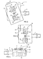
- the pedal 1 of the present invention includes a main body portion 2 which is mounted on an appropriate spindle 3 which in turn is attached to the pedal arm of a cycle.
- the body portion 2 preferably has a flat upper surface 4, and angled or profiled leading and rearward faces 7 and 8 so that the pedal is as streamlined as possible, especially for use in racing, touring and the like.
- the body portion 2 is preferably formed of an appropriate lightweight rigid material, for example an appropriate plastics material.
- an elongate, transverse bore is provided through which the spindle 3 of a pedal can pass.
- the bore is preferably in one form of the invention offset towards one end of the pedal 1, so that in 'non-use', one end thereof will depend downwardly from the spindle. This is by way of example only however.
- the upper surface 4 of the body portion 2 is substantially planar in formation and is provided with engagement means which are adapted to engage with appropriate engagement means provided on the sole of a shoe (to be described hereinafter).
- the pedal engagement means are preferably in the form of upwardly extending lugs 10 which have a main body portion 11 and at least one outwardly extending lip 12.
- the lips 12 extend outwardly from upper ends of the body portions 11 so as to define channels 14 therebelow.
- the pedal engagement lugs 10 are preferably longitudinally spaced apart on the upper surface 4 of the body portion.
- the lugs are preferably disposed in a substantially "fore and aft" arrangement, each being substantially offset to opposing sides of the longitudinal axis of the body portion.
- the lugs 10 are preferably so positioned that the lips 12 face or extend outwardly in substantially opposite directions and so that the channels 14 defined by the body portion and lips of the lugs extend in different directions, and face opposing sides of the body portion. It will be appreciated hereinafter that this is for the purposes of engagement of the pedal with a cycle shoe.
- a locating pin or similar member 15 is provided substantially medially of the body portion of the pedal.
- the pin 15 is preferably substantially intermediate the lugs 10. This will be described hereinafter.
- a spring portion 17 is formed.
- the spring portion 17 is elongate in formation and is formed and defined by an elongate and partial slot 18 extending partially across and adjacent one end of the body portion 2.
- the slot 18 preferably terminates in a hole or bore 19 extending through the pedal, which will assist in preventing splitting of the body portion 2 on pressure being applied to the spring portion 17.
- the spring portion 17 is thus formed by the transverse slot 18 and the spring portion has a normal orientation or position in which it is substantially normal to the remainder of the surface 4 of the pedal. Having regard to the properties of the material of the present invention and/or the formation of the slot will render the spring portion inherently resilient and spring biased, allowing it to move into and out of its position of normal orientation.
- the outer end of the spring portion 17 is preferably formed with an upwardly extending abutment member or ridge 20 which is integrally formed with the pedal and spring portion.
- the spring portion 17 and abutment member 20 are shown as being positioned at the front of the pedal 30. This is by way of example only however. It is considered that the invention has substantial advantages when a spring portion 17 and abutment member 20 are provided at or adjacent a rear of a pedal 30. Such an embodiment is shown in Figure 1a.
- the cycle engagement means are formed or provided in a plate 32 of an appropriate material (such as plastic or some other light and appropriate material), which is attached by suitable means to an underside of the shoe.
- suitable means such as plastic or some other light and appropriate material
- a plate 32 can be moulded into the lower surface or sole of a shoe during formation.
- the plate 32 has leading and trailing edges 33 and 34 which correspond substantially with the leading and trailing edges 7 and 8 of the body portion 2 of a pedal 1 so that once the shoe and pedal are engaged one with the other, the angled and profiled surfaces of the body portion 2 of the pedal 1 will continue up into the plate 32 of the shoe 30.
- the shoe engagement meaner are in the form of spaced apart rabbet recesses 21, of a substantially rectangular formation, each of which include a partially open portion 25 and a recessed tongue 26.
- the rabbets 21 are longitudinally spaced apart one from the other and are so located that on a shoe 30 being placed over the pedal 2, the open portions of the rabbets 21, are able to align with and are capable of substantially fitting over and engaging with, the lugs 10 of the pedal 1.
- a hole or bore 36 is provided in the underside of the shoe 30, substantially intermediate the rabbets 21, which hole or bore 36 will align with and accommodate the pivot pin 15 of the pedal. This will be described hereinafter.
- a stepped or cut out portion 37 which in use will engage with and behind the abutment member 20 of the spring portion 17 of the pedal 1. Again this will be described hereinafter.
- the shoe 30 is fitted to a wearer and is placed over the pedal 1.
- the shoe 30 is then brought down at an angle, so that the locating pin 15 of the pedal 1 is positioned within the hole or bore 36 of the plate 32 of the shoe 30.
- the longitudinal axis of the shoe 30 and plate 32 is then disposed at a substantially oblique angle to the longitudinal axis of the pedal 1.
- the abutment member 20 is upstanding and will prevent an inward and semi-rotational movement or pivot of the shoe and plate, inwardly of the pedal 1.
- the spring portion 17 and , abutment 20 will flex upwardly and return to their normal orientation in which the spring portion 17 is substantially normal to the top surface 4 of the pedal 1. In this position the abutment member 20 will be extending upwardly from the top surface 4 of the pedal 1 and will engage against the side of the stepped or cut out portion 37 at the front side of the plate 32.
- This engagement therefore provides a positive engagement between the pedal 1 and shoe 30; the abutment member 20 prevents or at least minimises casual, involuntary, or unintentional disengagement of the shoe 30 from the pedal 1.
- the spring portion 17 resiliently retains the abutment member 20 in its upwardly extending position in which it assists in holding the plate 32 and shoe 30 in position.
- the spring portion 17 and abutment member 20 are located at or adjacent the rear of a pedal 1, a cut out or stepped portion will be provided at an appropriate side adjacent the rear of the plate 32. In use therefore, the abutment member 20 will engage within the recess formed at or adjacent the rear of the plate 32, by such a stepped or cut out portion.
- the plate 32 attached to, or forming part of, the underside of the shoe 30 is a unitary and integral formation, the rabbets and cut out portion, together with the hole substantially medially thereof, being integrally formed as a unitary structure.
- This will be described hereinafter with reference to the inter-engagement of the cycle shoe and pedal. It should be appreciated however, that on a downward pressure being applied to the abutment member 20 and the spring portion 17, they will, due to their resilience, move or be biased downward away from the normal plane of the upper surface 4 of the pedal. In its normal position, the abutment member 20 will extend upwardly from the surface 4 of the pedal, on at least one side thereof. On downward pressure being applied thereto (or being applied to the spring member), the abutment member 20 will move out of and downwardly from, that position.
- the abutment member 20 extends across the width of the formed spring portion 17. It can however be of other dimensions if desired.
- the components of the pedal are integrally formed one with the other and are formed as a substantially unitary formation. This therefore provides a straightforward and efficient pedal for use in conjunction with the present invention and which overcomes the need to have replacement parts and separate mouldings and processes for manufacture and assembly.
- the leading and trailing faces 7 and 8 of the body portion 2 are angled and profiled so as to be as light and aerodynamic as possible.
- engagement means can be provided on a sole or lower surface thereof, in the form of recesses 21 which are adapted to engage with the lugs 10 of the pedal 1.
- the plate 32 is profiled such that it does not create a resistance during movement of the pedals and cycle; indeed at least the forward or leading edge 33 is profiled and angled so as to connect with and continue the angled profile of the leading or front edge 7 of the pedal 1.
- the plate 32 is also of a relatively thin nature, having a flat, planar, lower face, which does not have components or integers extending downwardly therefrom. Thus, where it may extend downwardly slightlyfrom a normal underside or sole of the shoe, this is only for a short distance and does not make it difficult for a cyclist to walk following dismounting from a cycle or an accident.
- a cyclist applies an outward, pivotal moment or movement to a foot and shoe 30, this being a predetermined and positive movement which must be of sufficient pressure to cause the spring portion 17 and abutment member 20 to flex and bias downwardly, this bringing the abutment member 20 out of engagement with the side of the plate 30 defined by the stepped or cut out portion 37.
- This then allows continued pivotal movement of the shoe 30 outwardly of the pedal so that the lugs 12 and rabbets 21 disengage one from the other. Following such disengagement, the spring portion 17 and abutment member 20 will return to their position of rest.
- the present invention has been described by way of example only, as having two spaced apart lugs and two spaced apart rabbets. This is particularly advantageous given the pivotal and semi-rotational moment to be applied to the shoe 30 to allow for the engagement and disengagement operations. However, if desired, other configurations or numbers of engagement means can be provided. As indicated hereinbefore, it is particularly advantageous that the components of the present invention be of a basically unitary and integral construction, this overcoming or minimising the problems that have been created up until this time, especially with arrangements which have incorporated a plurality of different components, (this in turn creating problems with manufacture, use, repair and replacement).
- the present invention also provides for an arrangement whereby a positive location is possible between a shoe and pedal, but whereby disengagement is possible in an equally straight forward and efficient manner, on a positive and predetermined movement of the shoe relative to the pedal.
- the construction and operation of the invention are straight forward and efficient, and provide a substantial advantage over those arrangements that have been known and suggested up until this time.
- the engagement means incorporated into the shoe 30 of the present invention do not present obstructions or integers which extend outwardly and downwardly from the shoe, such as to make it difficult or impossible for a cyclist to walk having come off or dismounted a cycle.
- the present invention therefore provides a substantial advantage over the arrangements suggested and disclosed up until this time.
Landscapes
- Engineering & Computer Science (AREA)
- General Health & Medical Sciences (AREA)
- Combustion & Propulsion (AREA)
- Transportation (AREA)
- Mechanical Engineering (AREA)
- Health & Medical Sciences (AREA)
- Chemical & Material Sciences (AREA)
- Physical Education & Sports Medicine (AREA)
- Footwear And Its Accessory, Manufacturing Method And Apparatuses (AREA)
- Electrophonic Musical Instruments (AREA)
- Mechanical Control Devices (AREA)
- Surgical Instruments (AREA)
- Auxiliary Drives, Propulsion Controls, And Safety Devices (AREA)
- Arrangement And Mounting Of Devices That Control Transmission Of Motive Force (AREA)
- Braking Systems And Boosters (AREA)
Claims (7)
Priority Applications (1)
| Application Number | Priority Date | Filing Date | Title |
|---|---|---|---|
| AT84306661T ATE42517T1 (de) | 1983-09-28 | 1984-09-28 | Pedalanordnung. |
Applications Claiming Priority (2)
| Application Number | Priority Date | Filing Date | Title |
|---|---|---|---|
| NZ205778A NZ205778A (en) | 1983-09-28 | 1983-09-28 | Interengagable cycle pedal and shoe |
| NZ205778 | 1983-09-28 |
Publications (3)
| Publication Number | Publication Date |
|---|---|
| EP0146218A2 EP0146218A2 (fr) | 1985-06-26 |
| EP0146218A3 EP0146218A3 (en) | 1986-04-16 |
| EP0146218B1 true EP0146218B1 (fr) | 1989-04-26 |
Family
ID=19920521
Family Applications (1)
| Application Number | Title | Priority Date | Filing Date |
|---|---|---|---|
| EP84306661A Expired EP0146218B1 (fr) | 1983-09-28 | 1984-09-28 | Agencement de pédale |
Country Status (6)
| Country | Link |
|---|---|
| US (1) | US4735107A (fr) |
| EP (1) | EP0146218B1 (fr) |
| JP (1) | JPS60107473A (fr) |
| AT (1) | ATE42517T1 (fr) |
| DE (1) | DE3477910D1 (fr) |
| NZ (1) | NZ205778A (fr) |
Families Citing this family (48)
| Publication number | Priority date | Publication date | Assignee | Title |
|---|---|---|---|---|
| DE3532926A1 (de) * | 1985-09-14 | 1987-03-26 | Loehr Edgar Dipl Agr Ing | Sicherheitsfusshaken |
| CH667779A5 (de) * | 1985-10-04 | 1988-11-15 | Ueli Eser | Verbindung zwischen einem pedal fuer ein fahrrad und einem schuh. |
| IT1196479B (it) * | 1986-07-08 | 1988-11-16 | Campagnolo Spa | Dispositivo di aggancio della scarpa di una ciclista al pedale di una bicicletta da competizione o sportiva |
| GB8707337D0 (en) * | 1987-03-27 | 1987-04-29 | Pettite A J | Bicycle pedal |
| IT210729Z2 (it) * | 1987-05-28 | 1989-01-11 | Rapisarda Antonio | Dispositivo per intercollegare un pedale di bicicletta ed una scarpa da ciclista |
| US4893523A (en) * | 1988-01-07 | 1990-01-16 | Lennon Dan C | Bicycle and pedal system |
| IT1220809B (it) * | 1988-03-08 | 1990-06-21 | Martin Antonio De | Metodo per l'avanzamento del piede particolarmente nei pedali per velocipedi |
| DE69018196T2 (de) * | 1989-11-14 | 1995-09-14 | Shimano Kk | Verbindungsstruktur zwischen Fahrradpedal und Stossplatte, Fahrradpedal und Stossplatte. |
| JPH04183694A (ja) * | 1990-11-13 | 1992-06-30 | Shimano Inc | 自転車用ペダル |
| US5546829A (en) * | 1991-12-09 | 1996-08-20 | Speedplay, Inc. | Clipless bicycle pedal system |
| FR2686232B1 (fr) * | 1992-01-22 | 1994-04-08 | Smdr Sarl | Dispositif d'accouplement demontable d'une piece solidaire d'une semelle de chaussure a une piece liee au pedalier d'une bicyclette. |
| FR2705080B1 (fr) * | 1993-05-10 | 1995-08-04 | De Lattre Bertrand | Dispositif de fixation d'une chaussure sur une pedale, et chaussure et pedale equipees d'un tel dispositif. |
| DE4431528A1 (de) * | 1994-09-03 | 1996-03-07 | Basf Ag | Verfahren zur Herstellung von n-Butyraldehyd und/oder n-Butanol |
| IT1320450B1 (it) * | 2000-06-23 | 2003-11-26 | Campagnolo Srl | Pedale di sicurezza per biciclette. |
| SE526839C2 (sv) * | 2003-09-22 | 2005-11-08 | Rolf Sjoeswaerd | System vid stigbygel |
| DE202005000498U1 (de) * | 2005-01-13 | 2006-05-24 | Marantec Antriebs- Und Steuerungstechnik Gmbh & Co. Kg | Vorrichtung zum Abhängen von Garagentorantrieben |
| US9003921B2 (en) * | 2007-10-10 | 2015-04-14 | The Hive Global | Removable pedal platform |
| US9826794B2 (en) | 2008-12-12 | 2017-11-28 | Speedplay, Inc. | Shoe sole mounting standard for bicycle cleat |
| US8745900B2 (en) | 2009-05-26 | 2014-06-10 | Speedplay, Inc. | Aerodynamic bicycle shoe cover and pedal cover |
| US8857292B2 (en) | 2010-11-01 | 2014-10-14 | Speedplay, Inc. | Pedal-cleat assembly |
| US20120132030A1 (en) * | 2010-11-29 | 2012-05-31 | Shimano Inc. | Bicycle pedal |
| USD662862S1 (en) | 2011-07-12 | 2012-07-03 | Schutz Paul A | Motorcycle footrest with heel retainer |
| US20130190714A1 (en) | 2012-01-19 | 2013-07-25 | Tekni-Plex, Inc | Multi-layered tubing |
| USD683273S1 (en) * | 2012-02-03 | 2013-05-28 | Keywin Sports Limited | Pedal body |
| ITTV20120186A1 (it) * | 2012-09-28 | 2014-03-29 | Alpinestars Res Srl | Calzatura sportiva |
| US10221887B2 (en) | 2012-12-06 | 2019-03-05 | The Hive Global, Inc | Self locking bearing preload adjuster |
| US9511817B2 (en) | 2013-03-14 | 2016-12-06 | Speedplay, Inc. | Pedal and cleat assembly |
| US9499231B2 (en) | 2013-03-14 | 2016-11-22 | Speedplay, Inc. | Pedal and cleat assembly |
| US10188171B2 (en) | 2014-01-22 | 2019-01-29 | Speedplay, Inc. | Alignment system for a cleat and base assembly |
| US10182609B2 (en) * | 2014-07-28 | 2019-01-22 | Speedplay, Inc. | Aperture cover for bicycle cleat assembly |
| US10279862B2 (en) | 2014-09-02 | 2019-05-07 | Speedplay, Inc. | Cleat assembly for clipless bicycle pedal |
| TWI678169B (zh) * | 2015-01-28 | 2019-12-01 | 巨大機械工業股份有限公司 | 用於迴轉踩踏式運動的運動用鞋 |
| US10562588B2 (en) | 2015-09-01 | 2020-02-18 | The Hive Global, Inc | Bicycle cassette with locking connection |
| US11142280B2 (en) | 2016-03-24 | 2021-10-12 | The Hive Global, Inc. | Bicycle crank with spindle attachment structure |
| CN110893610A (zh) | 2016-05-02 | 2020-03-20 | 凯特尔塑料有限公司 | 实用组件和联接机构 |
| WO2019028041A1 (fr) | 2017-07-31 | 2019-02-07 | Milwaukee Electric Tool Corporation | Système de dispositif de rangement |
| WO2019040340A1 (fr) | 2017-08-21 | 2019-02-28 | The Hive Global, Inc. | Cassette de bicyclette comprenant un raccordement par serrage |
| CN111615481B (zh) | 2017-12-20 | 2022-11-04 | 凯特尔塑料有限公司 | 台车及其机械制动系统 |
| CN111867785A (zh) | 2018-01-24 | 2020-10-30 | 米沃奇电动工具公司 | 工具储存装置 |
| IL257294A (en) | 2018-02-01 | 2018-03-29 | Milwaukee Electric Tool Corp | Coupleable crate |
| IL260225A (en) | 2018-06-24 | 2018-07-31 | Keter Plastic Ltd | pushcart |
| IL265964A (en) | 2019-04-11 | 2019-07-31 | Milwaukee Electric Tool Corp | A matching system and adapter for it |
| IL269564B2 (en) | 2019-09-23 | 2023-11-01 | Keter Home & Garden Products Ltd | Sawhorse |
| US11932351B2 (en) | 2020-07-17 | 2024-03-19 | The Hive Global, Inc. | Conical bicycle cassette sprocket structure |
| US20230320457A1 (en) * | 2020-08-21 | 2023-10-12 | The Regents Of The University Of Colorado, A Body Corporate | Dual purpose running and cycling shoe |
| WO2022186206A1 (fr) * | 2021-03-03 | 2022-09-09 | 株式会社国際気象コンサルタント | Pédale, cale, système de pédale et bicyclette |
| WO2022204158A1 (fr) | 2021-03-26 | 2022-09-29 | The Hive Global, Inc. | Tige de selle de bicyclette télescopique à hauteur réglable et insertion de cadre fixe |
| US12030586B2 (en) | 2021-07-12 | 2024-07-09 | The Hive Global, Inc. | Seal for bicycle crank with differential chainring motion |
Family Cites Families (17)
| Publication number | Priority date | Publication date | Assignee | Title |
|---|---|---|---|---|
| US550409A (en) * | 1895-11-26 | Island | ||
| FR993958A (fr) * | 1944-10-25 | 1951-11-09 | Cale-pied réglable à serrage automatique | |
| FR63554E (fr) * | 1952-12-04 | 1955-09-29 | Dispositif de fixation amovible d'une chaussure à la pédale d'un cycle | |
| US3788163A (en) * | 1972-06-27 | 1974-01-29 | Nasa | Manual actuator |
| US3858996A (en) * | 1972-10-19 | 1975-01-07 | Standard Pressed Steel Co | Bracket clip |
| FR2279607A1 (fr) * | 1974-07-24 | 1976-02-20 | Gormand Bruno | Ensemble constitue par une pedale de bicyclette et son cale-pied |
| FR2401823A1 (fr) * | 1977-09-01 | 1979-03-30 | Duran Louis | Cale-chaussure de cycliste agence a un dispositif automatique d'accrochage et de decrochage de la pedale |
| FR2442175A1 (fr) * | 1978-11-24 | 1980-06-20 | Badersbach Jean | Dispositif de fixation d'une chaussure sur une pedale de bicyclette |
| FR2449587A1 (fr) * | 1979-02-21 | 1980-09-19 | Lotteau Jacques | Dispositif d'accouplement de securite entre une pedale de cycle et la chaussure du cycliste |
| FR2464660A1 (fr) * | 1979-09-10 | 1981-03-20 | Camuset | Dispositif cale-pedale pour chaussure de cyclisme |
| EP0058438A3 (fr) * | 1981-02-13 | 1984-04-04 | Jean Badersbach | Pédale de bicyclette permettant l'accrochage d'une chaussure en position préréglée et chaussure de cycliste adaptée à ladite pédale |
| DE3149345A1 (de) * | 1981-12-12 | 1983-06-16 | Hubert 5100 Aachen Küpper | Bindung an fahrradpedalen |
| FR2526748B1 (fr) * | 1982-05-12 | 1987-05-29 | Christol Lilian | Dispositif de pedalage pour cycle et chaussure adaptee |
| FR2561502B1 (fr) * | 1983-11-29 | 1987-07-31 | Drugeon Jean Francois | Dispositif de fixation d'une chaussure sur une pedale et parties constitutives dudit dispositif |
| DE3414971A1 (de) * | 1984-04-19 | 1985-10-31 | Urban 8000 München Eser | Pedal fuer fahrraeder und schuh zur verwendung mit diesem pedal |
| FR2568213B1 (fr) * | 1984-07-27 | 1987-06-26 | Delafollie Gerard | Ensemble pedale-chaussure du type comportant un cale-pedale |
| FR2577768B1 (fr) * | 1985-02-28 | 1987-05-22 | Patrick Sa | Chaussure de cyclisme |
-
1983
- 1983-09-28 NZ NZ205778A patent/NZ205778A/en unknown
-
1984
- 1984-09-28 EP EP84306661A patent/EP0146218B1/fr not_active Expired
- 1984-09-28 JP JP59203909A patent/JPS60107473A/ja active Pending
- 1984-09-28 AT AT84306661T patent/ATE42517T1/de not_active IP Right Cessation
- 1984-09-28 DE DE8484306661T patent/DE3477910D1/de not_active Expired
-
1986
- 1986-07-14 US US06/884,903 patent/US4735107A/en not_active Expired - Fee Related
Also Published As
| Publication number | Publication date |
|---|---|
| US4735107A (en) | 1988-04-05 |
| JPS60107473A (ja) | 1985-06-12 |
| EP0146218A2 (fr) | 1985-06-26 |
| ATE42517T1 (de) | 1989-05-15 |
| NZ205778A (en) | 1986-05-09 |
| DE3477910D1 (en) | 1989-06-01 |
| EP0146218A3 (en) | 1986-04-16 |
Similar Documents
| Publication | Publication Date | Title |
|---|---|---|
| EP0146218B1 (fr) | Agencement de pédale | |
| US4807372A (en) | Cleated shoe walking sole | |
| JP2832531B2 (ja) | サイクリスト靴 | |
| US4055005A (en) | Cover for bicycling shoe to provide a walking surface | |
| US5446977A (en) | Cycling shoe having a sole with a removable portion | |
| US5363573A (en) | Rotatable cleat | |
| US5324219A (en) | Swimming flipper | |
| US4907355A (en) | Cycling shoe with adjustable cleat system | |
| US4188737A (en) | Sport shoes | |
| US5115692A (en) | Bicycle pedal | |
| US6595542B2 (en) | Snowboard binding system | |
| EP0735965B1 (fr) | Systeme de pedale de bicyclette ameliore ne comprenant pas d'attache | |
| US4876808A (en) | Running and cycling shoe | |
| US9254016B2 (en) | Device for adapting a shoe to attach a cycling cleat | |
| US6467795B1 (en) | Snowboard binding with highback | |
| US6231066B1 (en) | Active highback system for a snowboard boot | |
| US4662090A (en) | Bicycle shoe | |
| US5765854A (en) | Binding mounting system | |
| US8794105B2 (en) | Device for connecting a shoe to a sports article, such as a cycle pedal | |
| US6733031B2 (en) | Snowboard binding system | |
| US6193277B1 (en) | Walking sole for in-line skate | |
| US6536795B2 (en) | Snowboard binding system | |
| US6733030B2 (en) | Snowboard binding system | |
| US5450712A (en) | Spurs for riding shoes | |
| US6637768B2 (en) | Snowboard binding system |
Legal Events
| Date | Code | Title | Description |
|---|---|---|---|
| PUAI | Public reference made under article 153(3) epc to a published international application that has entered the european phase |
Free format text: ORIGINAL CODE: 0009012 |
|
| AK | Designated contracting states |
Designated state(s): AT BE CH DE FR GB IT LI LU NL SE |
|
| PUAL | Search report despatched |
Free format text: ORIGINAL CODE: 0009013 |
|
| AK | Designated contracting states |
Kind code of ref document: A3 Designated state(s): AT BE CH DE FR GB IT LI LU NL SE |
|
| 17P | Request for examination filed |
Effective date: 19860605 |
|
| 17Q | First examination report despatched |
Effective date: 19870108 |
|
| GRAA | (expected) grant |
Free format text: ORIGINAL CODE: 0009210 |
|
| AK | Designated contracting states |
Kind code of ref document: B1 Designated state(s): AT BE CH DE FR GB IT LI LU NL SE |
|
| PG25 | Lapsed in a contracting state [announced via postgrant information from national office to epo] |
Ref country code: SE Effective date: 19890426 Ref country code: LI Effective date: 19890426 Ref country code: IT Free format text: LAPSE BECAUSE OF FAILURE TO SUBMIT A TRANSLATION OF THE DESCRIPTION OR TO PAY THE FEE WITHIN THE PRESCRIBED TIME-LIMIT;WARNING: LAPSES OF ITALIAN PATENTS WITH EFFECTIVE DATE BEFORE 2007 MAY HAVE OCCURRED AT ANY TIME BEFORE 2007. THE CORRECT EFFECTIVE DATE MAY BE DIFFERENT FROM THE ONE RECORDED. Effective date: 19890426 Ref country code: FR Free format text: THE PATENT HAS BEEN ANNULLED BY A DECISION OF A NATIONAL AUTHORITY Effective date: 19890426 Ref country code: CH Effective date: 19890426 Ref country code: BE Effective date: 19890426 Ref country code: AT Effective date: 19890426 |
|
| REF | Corresponds to: |
Ref document number: 42517 Country of ref document: AT Date of ref document: 19890515 Kind code of ref document: T |
|
| REF | Corresponds to: |
Ref document number: 3477910 Country of ref document: DE Date of ref document: 19890601 |
|
| PG25 | Lapsed in a contracting state [announced via postgrant information from national office to epo] |
Ref country code: NL Effective date: 19890811 |
|
| REG | Reference to a national code |
Ref country code: CH Ref legal event code: PL |
|
| EN | Fr: translation not filed | ||
| PG25 | Lapsed in a contracting state [announced via postgrant information from national office to epo] |
Ref country code: GB Effective date: 19890928 |
|
| PG25 | Lapsed in a contracting state [announced via postgrant information from national office to epo] |
Ref country code: LU Free format text: LAPSE BECAUSE OF NON-PAYMENT OF DUE FEES Effective date: 19890930 |
|
| NLXE | Nl: other communications concerning ep-patents (part 3 heading xe) |
Free format text: IN PAT.BUL.20/89,PAGE 2774:DATE AND NUMBER OF HEADING PE,SECTION 2,HAS TO BE 891002/19 |
|
| PLBI | Opposition filed |
Free format text: ORIGINAL CODE: 0009260 |
|
| 26 | Opposition filed |
Opponent name: LOOK S.A. Effective date: 19891206 |
|
| GBPC | Gb: european patent ceased through non-payment of renewal fee | ||
| PG25 | Lapsed in a contracting state [announced via postgrant information from national office to epo] |
Ref country code: DE Effective date: 19900601 |
|
| PLBN | Opposition rejected |
Free format text: ORIGINAL CODE: 0009273 |
|
| STAA | Information on the status of an ep patent application or granted ep patent |
Free format text: STATUS: OPPOSITION REJECTED |
|
| 27O | Opposition rejected |
Effective date: 19911104 |
|
| PLAB | Opposition data, opponent's data or that of the opponent's representative modified |
Free format text: ORIGINAL CODE: 0009299OPPO |