EP0146248A2 - Codeur de MICR à plein champ - Google Patents
Codeur de MICR à plein champ Download PDFInfo
- Publication number
- EP0146248A2 EP0146248A2 EP84307577A EP84307577A EP0146248A2 EP 0146248 A2 EP0146248 A2 EP 0146248A2 EP 84307577 A EP84307577 A EP 84307577A EP 84307577 A EP84307577 A EP 84307577A EP 0146248 A2 EP0146248 A2 EP 0146248A2
- Authority
- EP
- European Patent Office
- Prior art keywords
- check
- hammer
- encoding
- ribbon
- font
- Prior art date
- Legal status (The legal status is an assumption and is not a legal conclusion. Google has not performed a legal analysis and makes no representation as to the accuracy of the status listed.)
- Granted
Links
Images

Classifications
-
- B—PERFORMING OPERATIONS; TRANSPORTING
- B41—PRINTING; LINING MACHINES; TYPEWRITERS; STAMPS
- B41J—TYPEWRITERS; SELECTIVE PRINTING MECHANISMS, i.e. MECHANISMS PRINTING OTHERWISE THAN FROM A FORME; CORRECTION OF TYPOGRAPHICAL ERRORS
- B41J9/00—Hammer-impression mechanisms
- B41J9/02—Hammers; Arrangements thereof
- B41J9/127—Mounting of hammers
-
- B—PERFORMING OPERATIONS; TRANSPORTING
- B41—PRINTING; LINING MACHINES; TYPEWRITERS; STAMPS
- B41J—TYPEWRITERS; SELECTIVE PRINTING MECHANISMS, i.e. MECHANISMS PRINTING OTHERWISE THAN FROM A FORME; CORRECTION OF TYPOGRAPHICAL ERRORS
- B41J33/00—Apparatus or arrangements for feeding ink ribbons or like character-size impression-transfer material
- B41J33/14—Ribbon-feed devices or mechanisms
- B41J33/38—Slow, e.g. "creep", feed mechanisms
- B41J33/388—Slow, e.g. "creep", feed mechanisms the ribbon being fed only when type impression takes place
-
- G—PHYSICS
- G06—COMPUTING OR CALCULATING; COUNTING
- G06K—GRAPHICAL DATA READING; PRESENTATION OF DATA; RECORD CARRIERS; HANDLING RECORD CARRIERS
- G06K13/00—Conveying record carriers from one station to another, e.g. from stack to punching mechanism
- G06K13/02—Conveying record carriers from one station to another, e.g. from stack to punching mechanism the record carrier having longitudinal dimension comparable with transverse dimension, e.g. punched card
-
- G—PHYSICS
- G06—COMPUTING OR CALCULATING; COUNTING
- G06K—GRAPHICAL DATA READING; PRESENTATION OF DATA; RECORD CARRIERS; HANDLING RECORD CARRIERS
- G06K17/00—Methods or arrangements for effecting co-operative working between equipments covered by two or more of main groups G06K1/00 - G06K15/00, e.g. automatic card files incorporating conveying and reading operations
Definitions
- This invention relates generally to the art of check encoders, and more specifically concerns a programmable, electronically controlled MICR (Magnetic Ink Character Recognition) check encoder.
- MICR Magnetic Ink Character Recognition
- MICR check encoder which is reliable and easy to operate, requiring relatively little counter space, as well as being conveniently programmable in the field, so that a manager or other individual at the bank branch or retail business may program the encoder to print desired information on a check as well as perform other desired processing functions, without extensive training.
- the present invention is directed to an apparatus for receiving, transporting and encoding checks, the apparatus being useful in a check encoder, comprising means for receiving a check from above the check receiving means; means for positioning the check in a selected position in the check receiving means prior to the time that. encoding (printing of a code) of the check is to begin; means for encoding the check, the check encoding means being located with the check receiving means, so that the check is inserted into the apparatus in the immediate vicinity of the check encoding means; and means for moving the check in said check receiving means so that it may be properly positioned for encoding of successive characters thereon.
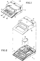
- Figures 1 and 2 show schematic views of the preferred embodiment of the check encoder of the present invention.
- the encoder is compact, electronically controlled and programmable. It is designed and sized to be used conveniently at a conventional teller's station, or at a new accounts desk in a bank.
- the encoder shown generally at 11 in the drawings, is in operation programmed to print a full field MICR code on a conventional bank check through a keyboard 13.
- the check may be conventional size (2 3/4" x 6") or other sizes.
- the keyboard 13 includes a conventional 10 key numeric pad 13a which can, if desired, accept alphabetic input, as well as a number of special symbol or function keys 13b.
- the keyboard 13 is the user interface with the software and follow-on electronic portions of the apparatus, which in turn operate the mechanical assemblies.
- the keyboard 13 is designed to provide a relatively sophisticated but convenient programming input capability for the encoder. Many check processing functions can be programmed by means of the keyboard. Further, several separate machine functions can be stacked or sequenced to- g ether by one keystroke, through the available programming capability.
- the software control of the encoder is arranged so that the programming of the encoder can be typically accomplished by a manager or other person located in the bank branch or other retail establishment, without the need of sophisticated training.
- the present encoder has an extensive field programming capability which can be fully utilized by customer personnel at the location of the encoder.
- the MICR code which is printed on the checks typically comprises 3 fields, each separated by a space.
- the first field (from right to left on the check) comprises 12 character positions, indicating the amount of the check.
- the second field comprises 18 character positions, indicating the full account number.
- the third field comprises 11 character.positions identifying the transit number for the bank.
- Display 15 is a dot matrix display so that symbols and foreign languages, as well as conventional alpha-numeric characters, can be shown on the display.
- a check guide 19, into which the check drops, is shown generally at 19 in Figures 2-4.
- Guide 19 extends the full width of the encoder, and in the embodiment shown is in the form of a narrow trough, comprising front and back sections 21 and 23, which are joined together at their respective lower edges to form a trough with a narrow, flat bottom.
- the guide 19 in the embodiment shown is approximately 1 1/2 inches high, so that when an inserted check rests on the bottom of the tray, approximately 1 1/2 inches of the check extends above the top of the tray.
- the back section 23 of check guide 19, in the em- bodicent shown, includes a narrow horizontal base portion 23a which extends forwardly of the remainder of back section 23, an intermediate, substantially vertical portion 23c, and a top portion 23b which flares backwardly and at an angle from the remainder of back section 23.
- Front section 21 has a base portion 21a to that of back section 23, with portion 21a resting on top of and secured to base portion 23a of back section 23.
- An intermediate section 21c is similar to portion 23c of back section 23, while a top portion 21b flares forwardly and at an angle relative to the remainder of front section 21.
- Back and front sections 23 and 21 gradually diverge from each other from bottom to top in the embodiment shown. At the bottom of the two sections, they are separated by approximately l/16th inch, while at the top, they are separated by a slightly greater distance. The check thus may be easily inserted by the operator into the check guide.
- the back section 23 is slightly higher than front section 21, to further facilitate insertion of a check into guide 19.
- the front and back sections 21 and 23 of check guide 19 both are cut out in several areas, to accommodate various portions of the encoder which operate on the check, all of which are described in more detail hereinafter.
- the configuration of the guide, and the arrangement of the checking sensing system, the check transport system and the check printing system are all significant because the check is essentially dropped directly into the printing mechanism, instead of being inserted into an off-line guide and then being clamped and guided into the printing mechanism.
- the check sensing system provides the information by which the check is initially properly positioned for encoding.
- Positioned at the bottom of the guide 19 approximately 2 3/4 inches apart are two conventional infrared sensor assemblies 25 and 27.
- Sensor 25 comprises one infrared light source and a light detector, on opposite sides of the check guide 19, while sensor 27 includes a pair of light sources and detectors, one pair being slightly elevated to detect the leading edge of the check.
- sensors 25 and 27 sense the proper seating and position of the check.
- Sensor 25 and the bottom edge sensor portion of sensor 27 check the bottom edge of the check. Once the bottom edge is determined to be seated properly, as determined by the condition of sensor 25 and the bottom edge sensor portion of sensor 27P, the check moving system, which positions the check lengthwise, and the printing system are enabled. If the check is not seated properly, then the positioning and printing systems are not enabled. The operator will then remove and re-insert the check.
- the check transport system includes two fixed roller assemblies 29 and 31 positioned slightly to the front of check guide 19 and two movable roller assemblies 33 and 35 positioned slightly to the rear of the check guide.
- the fixed roller assemblies 29 and 31 are positioned approximately 3 1/4 inches apart, slightly forwardly of front section 21 of check guide 19.
- Each fixed roller assembly, such as for instance roller assembly 29, includes a vertical mount rod 37 which extends through a horizontal support plate portion 39 of encoder 11.
- the mount rod 37 has a length of 3 1/4 inches in the embodiment shown.
- a serrated roller 41 At the top of mount rod 37 is made of steel and has a diameter of approximately 5/8th inch and a height of approximately 1/2 inch.
- the edge of the serrated roller 41 is at its nearest point almost adjacent the front surface of front section 21 of check guide 19.
- the top of serrated roller 41 is approximately 1 3/8 inches above support plate 39, while mount rod 37 extends below support plate 39 approximately 1 3/4 inches.
- At the bottom end of rod 37 is a pulley 42.
- Roller 41, rod 37 and pulley 42 rotate together.
- a stepper motor 44 has a pulley 46 secured to its driveshaft. Pulley 46 is in the same plane as the pulley on the mounting rods of the respective fixed roller assemblies 29 and 31.
- a drive belt 48 connects the three pulleys.
- Each movable roller assembly such as. roller 33 for example, includes a mount rod 43 and a rubber roller 45 which is mounted at the top of mount rod 43.
- Roller 45 in the embodiment shown is nonmetal, of molded polyurethane, approximately 1 inch in diameter and approximately 1/2 inch high.
- Mount rod 43 is connected to a mounting plate 47 which in turn is mounted on opposing end pins 48a and 48b which rotate in fixed end mounts 50a, 50b.
- the fixed end mounts are attached to the frame of the encoder.
- Mounting plate 47 rotates about a horizontal axis, so that the respective rollers on the movable roller assemblies move toward and away from the back section 23 of check guide 19.
- Mounting plate 47 is rotated by means of a link plate 49 and a solenoid 51.
- the solenoid is conventional, and when activated by an electrical signal, draws one end 49a of link plate 49 upwardly against the bias of spring 52.
- the other end 49b of link plate 49 is connected to the center of mounting plate 47, so that when the one end 49a of link plate 49 is moved upwardly, the polyurethane rollers 45 move toward check guide 19, through cutout portions in the back section 23 sufficiently that the check is captured or gripped between serrated rollers 41 and polyurethane rollers 45.
- the movable roller assemblies 33 and 35 are in this position, the check is held securely, so that it may be transported.
- stepper motor 44 When the check is gripped by the check holding means, as described above, the check may be transported horizontally in the check tray by energizing stepper motor 44.
- stepper motor 44 When stepper motor 44 is energized, pulley 46 turns, which results in pulleys 42 being turned by means of drive belt 48. This results in turning of rollers 41, which causes the check to move.
- the use of a serrated edge of hard material such as steel for the fixed but rotatable rollers in combination with a molded polyurethane for the movable rollers has been found by the inventors to provide a reliable and advantageous means of transporting the check in the check guide accurately without tearing or crumpling the check, so as to permit high quality printing on the check.
- Another pair of rollers may be provided downstream of rollers 31 and 35 in order to facilitate batch printing of checks. These rollers would be positioned at cutout portions 36 in the check guide. The roller would be also driven from stepper motor 44.
- the check When the check has been properly seated in the check guide, and the check has been gripped, the check is transported initially toward the left hand side of the encoder until the right hand or leading edge of the check passes by the leading edge portion of sensor 27. The true position of the check relative to the fixed print means is then known. This is the base position for the check. The check is further transported under programmed instructions either right or left to the first character position in the desired field to be printed, in which position actual printing of the check begins.
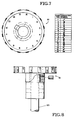
- the print mechanism includes a font wheel assembly which includes a font wheel 61, which is mounted on the motor shaft 63 of a stepper motor 64, which in turn is positioned on the underside of support plate 39. Font wheel 61 in the embodiment shown has 16 character positions on its edge surface, with the respective characters arranged as shown in Figure 7.
- the two most common characters i.e. the character symbol for "amount” and the "zero” character appear twice on the font wheel, the symbol for amount appearing at positions 1 and 9, which are 180 degrees apart, while the zero character appears at positions 2 and 10, also 180 degrees apart.
- This arrangement has the advantage of increasing the speed of the printing of the check, as the font wheel will move to the closest position for those two symbols.
- the actual rotational position of the font wheel 61 is determined through an infrared sensor, the light source being on the font assembly, and the light detector being in a fixed position spaced apart from the light source.
- the stepper motor 64 controlled by electrical signals, rotates font wheel 61 through motor shaft 63, to which the font wheel is connected by a roll pin.
- the font wheel 61 is rotated the shortest distance until the character to be printed is in the print position relative to the check.
- FIG. 3 The portion of the print assembly which is positioned to the rear of check guide 19 is shown in Figures 3, 4 and 6.
- This portion includes an assembly mounting block 81 which is secured to support plate 39.
- a cylindrical hammer mount 83 In the assembly mounting block is positioned a cylindrical hammer mount 83.
- Hammer mount 83 is held in the assembly mounting block 81 by means of a pin 85.
- pin 85 When pin 85 is removed, hammer mount 83 is moved upwardly from mounting block 81 by the action of a spring (not shown) beneath hammer mount 83.
- Hammer mount 83 is generally cylindrical, but has a slightly larger diameter at both ends than the center portion, and in the embodiment shown is 1 inch in diameter and 2 1/4 inches long.
- a hammer element 87 is positioned horizontally in hammer mount 83, in opening 88. Hammer element 87 is retained in hammer mount 83 and biased in a rearward position by means of a spring 89 which fits in opening 88 in hammer mount 83
- the hammer element 87 is a delrin rod, 1 inch long and 3/16 inches in diameter. Hammer element 87 is positioned such that when it is activated, it quickly moves horizontally through an opening in the back portion 23 of the check guide, pressing. the check against.font wheel 61. A ribbon positioned between the check and the font provides the ink for the printing of the character, as more fully described hereinafter.
- the use of a delrin rod as a hammer element is advantageous, since because of its relatively light weight, there is no resulting indentation (embossing) of the check, which is an undesirable result of the printing mechanism of conventional check encoders.
- hammer element 87 is moved forwardly under a high impact pressure by means of a solenoid 91 which acts against the rear end 94 of hammer element 87.
- a solenoid 91 which acts against the rear end 94 of hammer element 87.
- the solenoid 91 When the solenoid 91 is energized and strikes the hammer element 87, the hammer 87 first moves forward at a high speed against the action of spring 89, so that the front end 95 of hammer element 87 presses the check against the font wheel 61.
- the spring 89 then returns hammer element 87 rearwardly to its original position.
- the print quality is adjusted by changing the pulse width of the signal applied to solenoid 91 and by controlling the position of the font wheel. If darker print is desired, the pulse width of the electrical signal controlling the solenoid can be increased. This increases the speed of the hammer element. If the print quality is uneven in the same character, the rotational position of the font may be varied in very small increments, so that the hammer element strikes the font character evenly. Also, the alignment of the printed character on the check may be varied.
- the stepper motors used in the embodiment shown are 1.8 degree step size motors, which, with software and electronic control further dividing each step into 8 mini-steps, provides a high resolution of movement, and hence very good control over print quality and other operations of the apparatus.
- the adjustment of the timing and phasing of the electrical signals controlling the stepper motors is accomplished through the software, from instructions provided through keyboard 13. These adjustments optimize the changes in the speed of the rotor as well as settling time.
- the electromagnets in the motors can be energized at any current level in either direction. Two quasi- sin waves, 90 degrees out of phase, are used to energize the motors. With digital timing/phasing control provided by the software, there exist 3 possible different current levels on each of the two coils, in either direction, in addition to a zero current level, for a total of 32 usefully different positions per electrical cycle.
- the ink for the printing of the characters is provided by a MICR ribbon, which is housed in a removable cartridge 95, shown in Figure 2.
- the cartridge itself is conventional and is commercially available.
- Cartridge 95 is positioned on the upper surface of support frame 39 with its the back edge against a retaining clip 97, which is otherwise biased forwardly by spring 99.
- the ribbon is moved with each new character to be printed by stepper motor 100, which acts on the cartridge through a drive element 101 in conventional fashion. A clean portion of ribbon is thus presented between the font wheel 61 and the hammer element 87 for each character printed.
- Cartridge ribbons have not been used heretofore because the reel ribbons have been able to print a greater number of characters without changing the ribbon. In the present invention, however, the ribbon is advanced a par- t icular distance for each successive character to be printed, the distance depending on the width of the next successive character, rather than a fixed distance.
- a lookup table is provided in the embodiment shown which has stored in it the print width of each character on the font wheel.
- the width of the next character Prior to each character being printed, and hence prior to the ribbon being advanced for the next character, the width of the next character is determined from the lookup table and the ribbon is accordingly advanced sufficiently to result in a fixed distance between the trailing edge of the previous character printed and the leading edge of the next character. This results in substantial savings in the use of the ribbon.
- the ribbon is advanced a set distance for each character, which actually results in a varying distance between each character, because the actual width of the characters are different.
- a cartridge ribbon can produce as many characters as a conventional pancake-type ribbon arrangement.
- changing a ribbon is very convenient, unlike conventional encoders.
- the removal of the ribbon cartridge 95 has the effect of releasing pin 85, so that hammer mount 83 is released and pops up when the cartridge 95 is removed.
- the delrin rod hammer element 87 used in the embodiment shown may be conveniently replaced by turning the element 87 to release it from themount.
- FIG. 3 The mechanism for releasing pin 85 is shown in Figures 3, 4 and 6.
- a long horizontal rod 98 connects retaining clip 97 and one end of a rotatable tab element 102.
- Tab 102 is positioned to the rear of assembly mounting block 81, and rotates in a horizontal plane on the upper surface of support plate 39.
- spring 99 moves retaining clip 97 such that rod 98 moves to the rear, rotating tab 102 in a clockwise direction.
- pin 85 which is connected to the other end of t ⁇ b 102, moving out of its slot in counting block 81, thus releasing hammer mount 83.
- tab 102 When a new ribbon cartridge is seated, its back against clip 97, against the bias of spring 99, tab 102 is rotated counterclockwise, moving pin 85 into its slot in mounting block 81, engaging hammer mount 83.
- a check is dropped into the check guide, the apparatus initially positions each check correctly in the check guide and then prints each check from right to left, in accordance with programmed information which is shown on the display.
- the check is moved the desired distance, the font wheel is rotated to present the desired character, the ribbon is moved the desired amount, and the hammer is actuated, printing the check.
- FIG. 9 shows in functional block diagram form the basic control arrangement.
- the software control 111 of the apparatus which is disclosed in an attached appendix, is stored in an E PROM in the embodiment shown, connected to a main electronics board (not shown) which includes a power supply for the encoder.
- the EPROM contains 16K of memory and the program is loaded at the factory.
- a RAM random access memory
- the RA M has a battery backup in the embodiment shown.
- the original program thus may be redefined by the user in the field to suit his needs.
- the program controls what is to be displayed, what is to be printed on the check, including automatic check sequencing operations, and also what is to be printed in hard copy, as the encoder software has the capability of controlling a printer to accompany the encoder.
- the keyboard and its electronic circuitry 113 and the sensors 115 provide input information to program control 111.
- the program control 111 then provides the proper signals, including proper levels and timing, to control the stepper motors which operate the ribbon assembly 117, the check transport system 119, and the font wheel assembly 121. Signals are also provided to the display section with its associated electronics 123, to the printer solenoid 125 which actuates the print hammer, and to the hard copy printer and its associated electronics 127, if the encoder is provided with a printer. Connections are provided from the main electronics circuit board to the respective electronics boards for the printer, the keyboard, the display, and the sensors.
- the main electronics board also includes a plug connection by which one encoder may be connected to another, to load the field program data in RAM storage therein, under control of the program control 111. This is referred to in the art as downloading and is shown in function block 129 in Figure 9.
- a compact MICR encoder which is capable of being conveniently programmed in the field.
- the mechanical systems are arranged to be actuated and operated independently of each other, by virtue of the control portion of the encoder. Further, the mechanical systems are designed so that the check is inserted into the check guide substantially directly into the printing system. All of this results in a compact, reliable, operationally flexible encoder.
Landscapes
- Physics & Mathematics (AREA)
- General Physics & Mathematics (AREA)
- Engineering & Computer Science (AREA)
- Theoretical Computer Science (AREA)
- Accessory Devices And Overall Control Thereof (AREA)
- Transmission And Conversion Of Sensor Element Output (AREA)
- Analogue/Digital Conversion (AREA)
- Gyroscopes (AREA)
- Printers Characterized By Their Purpose (AREA)
- Handling Of Cut Paper (AREA)
- Dot-Matrix Printers And Others (AREA)
- Impression-Transfer Materials And Handling Thereof (AREA)
Priority Applications (1)
| Application Number | Priority Date | Filing Date | Title |
|---|---|---|---|
| AT84307577T ATE51311T1 (de) | 1983-11-08 | 1984-11-02 | Gesamtfeld-micr-kodierer. |
Applications Claiming Priority (2)
| Application Number | Priority Date | Filing Date | Title |
|---|---|---|---|
| US06/549,818 US4624588A (en) | 1983-11-08 | 1983-11-08 | Full field MICR encoder |
| US549818 | 1983-11-08 |
Publications (3)
| Publication Number | Publication Date |
|---|---|
| EP0146248A2 true EP0146248A2 (fr) | 1985-06-26 |
| EP0146248A3 EP0146248A3 (en) | 1985-10-09 |
| EP0146248B1 EP0146248B1 (fr) | 1990-03-21 |
Family
ID=24194486
Family Applications (1)
| Application Number | Title | Priority Date | Filing Date |
|---|---|---|---|
| EP84307577A Expired - Lifetime EP0146248B1 (fr) | 1983-11-08 | 1984-11-02 | Codeur de MICR à plein champ |
Country Status (8)
| Country | Link |
|---|---|
| US (1) | US4624588A (fr) |
| EP (1) | EP0146248B1 (fr) |
| JP (1) | JPS60155468A (fr) |
| AT (1) | ATE51311T1 (fr) |
| AU (1) | AU579840B2 (fr) |
| CA (1) | CA1255243A (fr) |
| DE (1) | DE3481738D1 (fr) |
| IN (1) | IN161838B (fr) |
Cited By (2)
| Publication number | Priority date | Publication date | Assignee | Title |
|---|---|---|---|---|
| FR2584211A1 (fr) * | 1985-06-28 | 1987-01-02 | Cga Alcatel | Terminal portatif pour carte a memoire. |
| US4706563A (en) * | 1984-03-02 | 1987-11-17 | Takahide Kazui | Card printer by means of a card feeding and type selecting printing method |
Families Citing this family (18)
| Publication number | Priority date | Publication date | Assignee | Title |
|---|---|---|---|---|
| US4625275A (en) * | 1984-04-03 | 1986-11-25 | Republic Money Orders, Inc. | Apparatus for dispensing money orders |
| US4878773A (en) * | 1988-06-08 | 1989-11-07 | Ncr Corporation | Ribbon feed control apparatus and method |
| DE3819782A1 (de) * | 1988-06-10 | 1989-12-14 | Triumph Adler Ag | Schreibmaschine, drucker oder dergleichen und farbbandkassette hierfuer |
| JP2524781Y2 (ja) * | 1988-08-05 | 1997-02-05 | アルプス電気株式会社 | プリンタにおける紙送りローラ構造 |
| US4891240A (en) * | 1988-09-06 | 1990-01-02 | Storage Technology Corporation | MICR character coating system |
| US4991983A (en) * | 1988-09-09 | 1991-02-12 | Global Technology International, Inc. | MICR encoder |
| US5035521A (en) * | 1990-02-06 | 1991-07-30 | Addressease, Inc. | Envelope printing mechanism |
| US5080509A (en) * | 1990-02-06 | 1992-01-14 | Addressease, Inc. | Envelope printing mechanism |
| GB2243336A (en) * | 1990-04-24 | 1991-10-30 | Esselte Meto Int Gmbh | Portable printers. |
| US5061100A (en) * | 1990-12-28 | 1991-10-29 | Ncr Corporation | Printer mechanism with vertically displaceable printing means for use with horizontal sheet feed mechanism |
| US5479532A (en) * | 1993-03-31 | 1995-12-26 | Direct Data Systems | Apparatus for reading magnetic information from a document having a read head mounted on a circuit board portion permitting resilient deflection |
| US5367581A (en) * | 1993-03-31 | 1994-11-22 | Direct Data Systems | Magnetic reader with read head biased against document by resilient deflection of circuit board |
| US5774879A (en) * | 1993-12-27 | 1998-06-30 | First Data Corporation | Automated financial instrument processing system |
| US5470160A (en) * | 1994-01-03 | 1995-11-28 | Nowlin; Linda | Check preparation method and apparatus incorporating check sum proof entry |
| US5895904A (en) * | 1997-05-27 | 1999-04-20 | Y. Nissim Coporation | Magnetic ink character recognition encoder utilizing a dot matrix printer head and plurality of sensors for detecting, activating, and controlling the speed of the media |
| KR100613529B1 (ko) * | 1998-04-01 | 2006-08-16 | 세이코 엡슨 가부시키가이샤 | 자기판독장치 및 프린터 |
| AU2001286048A1 (en) | 2000-09-11 | 2002-03-26 | Zipher Limited | Tape drive and printing apparatus |
| US7648678B2 (en) | 2002-12-20 | 2010-01-19 | Dako Denmark A/S | Method and system for pretreatment of tissue slides |
Family Cites Families (36)
| Publication number | Priority date | Publication date | Assignee | Title |
|---|---|---|---|---|
| US3254373A (en) * | 1963-10-10 | 1966-06-07 | Eastman Kodak Co | Tow blooming |
| US3401783A (en) * | 1965-12-30 | 1968-09-17 | Ibm | Proportional ribbon feed mechanism |
| US3645371A (en) * | 1969-11-26 | 1972-02-29 | Arthur Jovis | Printing means for sorting and routing system |
| US3768078A (en) * | 1970-08-31 | 1973-10-23 | R Williams | Encode selector system |
| US3659524A (en) * | 1970-10-15 | 1972-05-02 | Burroughs Corp | Printer control system |
| US3712211A (en) * | 1970-10-30 | 1973-01-23 | Burroughs Corp | Alignment means for a bed and platen printing machine |
| US3831731A (en) * | 1972-10-27 | 1974-08-27 | Burroughs Corp | Self-tensioning and re-inking ribbon cartridge for endless ribbons |
| US3845709A (en) * | 1973-02-26 | 1974-11-05 | Iomec Corp | Multifont selection |
| US3964384A (en) * | 1974-03-11 | 1976-06-22 | Sperry Rand Corporation | High speed printing mechanism |
| US3981236A (en) * | 1974-03-11 | 1976-09-21 | Sperry Rand Corporation | Printhead for impact printer |
| GB1504770A (en) * | 1974-08-30 | 1978-03-22 | Siemens Ag | Printer ribbon drive arrangement |
| JPS5142617A (ja) * | 1974-10-04 | 1976-04-10 | Nippon Denshi Zairyo Kk | Kogitsutetonohatsukoki |
| US4014258A (en) * | 1975-08-29 | 1977-03-29 | Wassermann Carl I | High speed printing apparatus |
| US4062285A (en) * | 1975-10-15 | 1977-12-13 | Xerox Corporation | Hammer driver controller for impact printers |
| US4189997A (en) * | 1976-01-16 | 1980-02-26 | Canon Kabushiki Kaisha | Printer |
| US4069755A (en) * | 1976-01-20 | 1978-01-24 | Burroughs Corporation | Ribbonless endorser for printing both fixed and variable information on moving documents |
| US4037532A (en) * | 1976-03-08 | 1977-07-26 | Xerox Corporation | Hammer assembly |
| US4056183A (en) * | 1976-05-07 | 1977-11-01 | Burroughs Corporation | Ribbonless endorser having a shiftable inked platen and feed roller |
| US4078485A (en) * | 1976-05-17 | 1978-03-14 | Computer Entry Systems, Inc. | Print wheel control |
| NL7607250A (nl) * | 1976-06-30 | 1978-01-03 | Ibm Nederland | Documentenverwerkingsinrichting. |
| US4401026A (en) * | 1977-09-14 | 1983-08-30 | Exxon Reserach And Engineering Co. | Free flight hammer for impact printer |
| US4155842A (en) * | 1977-10-12 | 1979-05-22 | Burroughs Corporation | Document hold and view station for high speed item sorter apparatus |
| US4217055A (en) * | 1978-05-30 | 1980-08-12 | Qume Corporation | Daisy wheel printer which accommodates different print wheel fonts |
| GB2026392A (en) * | 1978-07-31 | 1980-02-06 | Bunker Ramo | Printer |
| US4212549A (en) * | 1978-09-05 | 1980-07-15 | Dataproducts Corporation | Disc printer |
| US4196846A (en) * | 1978-11-13 | 1980-04-08 | Recognition Equipment Incorporated | Document processing transport |
| FR2441879A1 (fr) * | 1978-11-17 | 1980-06-13 | Automatisme Cie Gle | Procede de positionnement d'un mobile et imprimante fonctionnant selon ledit procede |
| JPS5586243U (fr) * | 1978-12-06 | 1980-06-14 | ||
| US4243330A (en) * | 1979-01-15 | 1981-01-06 | Burroughs Corporation | Dot printer adjustable endless loop ribbon cartridge transport apparatus |
| US4255061A (en) * | 1979-02-28 | 1981-03-10 | Burroughs Corporation | Control circuitry for actuation of a ribbonless endorser for printing variable information onto moving documents |
| JPS55140579A (en) * | 1979-04-20 | 1980-11-04 | Seiko Epson Corp | Electronic typewriter |
| JPS5610473A (en) * | 1979-07-02 | 1981-02-02 | Ncr Co | Structure of printingghammer |
| JPS5654583A (en) * | 1979-10-09 | 1981-05-14 | Hitachi Koki Co Ltd | Expanded-character print controller of printer |
| JPS5770681A (en) * | 1980-10-21 | 1982-05-01 | Ricoh Co Ltd | Hammering device for printer |
| AU530568B2 (en) * | 1980-10-31 | 1983-07-21 | Canon Kabushiki Kaisha | Serial printing apparatus with memory and display |
| AU2334284A (en) * | 1982-11-22 | 1984-06-18 | Siler, M.D. | Method and apparatus for making checks |
-
1983
- 1983-11-08 US US06/549,818 patent/US4624588A/en not_active Expired - Fee Related
-
1984
- 1984-10-31 CA CA000466694A patent/CA1255243A/fr not_active Expired
- 1984-11-02 AT AT84307577T patent/ATE51311T1/de not_active IP Right Cessation
- 1984-11-02 DE DE8484307577T patent/DE3481738D1/de not_active Expired - Lifetime
- 1984-11-02 EP EP84307577A patent/EP0146248B1/fr not_active Expired - Lifetime
- 1984-11-02 AU AU34920/84A patent/AU579840B2/en not_active Ceased
- 1984-11-05 JP JP59233036A patent/JPS60155468A/ja active Pending
- 1984-11-12 IN IN779/CAL/84A patent/IN161838B/en unknown
Cited By (2)
| Publication number | Priority date | Publication date | Assignee | Title |
|---|---|---|---|---|
| US4706563A (en) * | 1984-03-02 | 1987-11-17 | Takahide Kazui | Card printer by means of a card feeding and type selecting printing method |
| FR2584211A1 (fr) * | 1985-06-28 | 1987-01-02 | Cga Alcatel | Terminal portatif pour carte a memoire. |
Also Published As
| Publication number | Publication date |
|---|---|
| IN161838B (fr) | 1988-02-13 |
| CA1255243A (fr) | 1989-06-06 |
| EP0146248A3 (en) | 1985-10-09 |
| ATE51311T1 (de) | 1990-04-15 |
| AU579840B2 (en) | 1988-12-15 |
| JPS60155468A (ja) | 1985-08-15 |
| AU3492084A (en) | 1985-05-16 |
| EP0146248B1 (fr) | 1990-03-21 |
| DE3481738D1 (de) | 1990-04-26 |
| US4624588A (en) | 1986-11-25 |
Similar Documents
| Publication | Publication Date | Title |
|---|---|---|
| EP0146248A2 (fr) | Codeur de MICR à plein champ | |
| US5499876A (en) | Printing apparatus having head gap adjusting device | |
| US4375189A (en) | Label printer | |
| US4547780A (en) | Printer with manual paper feed and weigh scale incorporating the same | |
| EP0895868B1 (fr) | Dispositif pour le traitement d' un moyen d'enregistrement contenant des informations | |
| AU613959B2 (en) | Document handling apparatus | |
| EP1017568A1 (fr) | Procede de controle de support servant a eliminer l'impression d'images au-dela des limites du support | |
| US4070963A (en) | Impact line printer | |
| US5997192A (en) | Thermal transfer MICR point-of-sale printer with bi-directional clutch | |
| EP0900751B1 (fr) | Appareil d'alimentation de documents | |
| JP2759379B2 (ja) | 有価証券の印字装置 | |
| US4655625A (en) | Single station printer for printing on plural record media | |
| GB2159101A (en) | Selective printing | |
| US5091738A (en) | Printing apparatus and method | |
| US4980704A (en) | Printing apparatus and method | |
| US5377586A (en) | Paper roll support apparatus | |
| JP3366698B2 (ja) | 印字装置 | |
| US5019841A (en) | Printing apparatus and method | |
| US4958171A (en) | Printing apparatus and method | |
| JP2667705B2 (ja) | 磁気ストライプ処理装置 | |
| JP3716551B2 (ja) | 記録媒体の情報検出装置及び情報検出方法 | |
| JPH01145969A (ja) | ロール状原紙の終端検出装置 | |
| US5012261A (en) | Printing apparatus and method | |
| US4851864A (en) | Printing apparatus and method | |
| JPH042109B2 (fr) |
Legal Events
| Date | Code | Title | Description |
|---|---|---|---|
| PUAI | Public reference made under article 153(3) epc to a published international application that has entered the european phase |
Free format text: ORIGINAL CODE: 0009012 |
|
| AK | Designated contracting states |
Designated state(s): AT BE CH DE FR GB IT LI LU NL SE |
|
| PUAL | Search report despatched |
Free format text: ORIGINAL CODE: 0009013 |
|
| AK | Designated contracting states |
Designated state(s): AT BE CH DE FR GB IT LI LU NL SE |
|
| 17P | Request for examination filed |
Effective date: 19851230 |
|
| 17Q | First examination report despatched |
Effective date: 19870507 |
|
| GRAA | (expected) grant |
Free format text: ORIGINAL CODE: 0009210 |
|
| AK | Designated contracting states |
Kind code of ref document: B1 Designated state(s): AT BE CH DE FR GB IT LI LU NL SE |
|
| PG25 | Lapsed in a contracting state [announced via postgrant information from national office to epo] |
Ref country code: SE Effective date: 19900321 Ref country code: NL Effective date: 19900321 Ref country code: LI Effective date: 19900321 Ref country code: CH Effective date: 19900321 Ref country code: BE Effective date: 19900321 Ref country code: AT Effective date: 19900321 |
|
| REF | Corresponds to: |
Ref document number: 51311 Country of ref document: AT Date of ref document: 19900415 Kind code of ref document: T |
|
| ITF | It: translation for a ep patent filed | ||
| REF | Corresponds to: |
Ref document number: 3481738 Country of ref document: DE Date of ref document: 19900426 |
|
| ET | Fr: translation filed | ||
| REG | Reference to a national code |
Ref country code: CH Ref legal event code: PL |
|
| NLV1 | Nl: lapsed or annulled due to failure to fulfill the requirements of art. 29p and 29m of the patents act | ||
| PG25 | Lapsed in a contracting state [announced via postgrant information from national office to epo] |
Ref country code: LU Free format text: LAPSE BECAUSE OF NON-PAYMENT OF DUE FEES Effective date: 19901130 |
|
| PLBE | No opposition filed within time limit |
Free format text: ORIGINAL CODE: 0009261 |
|
| STAA | Information on the status of an ep patent application or granted ep patent |
Free format text: STATUS: NO OPPOSITION FILED WITHIN TIME LIMIT |
|
| 26N | No opposition filed | ||
| PGFP | Annual fee paid to national office [announced via postgrant information from national office to epo] |
Ref country code: GB Payment date: 19911206 Year of fee payment: 8 |
|
| PGFP | Annual fee paid to national office [announced via postgrant information from national office to epo] |
Ref country code: FR Payment date: 19911216 Year of fee payment: 8 |
|
| PGFP | Annual fee paid to national office [announced via postgrant information from national office to epo] |
Ref country code: DE Payment date: 19920120 Year of fee payment: 8 |
|
| PG25 | Lapsed in a contracting state [announced via postgrant information from national office to epo] |
Ref country code: GB Effective date: 19921102 |
|
| ITTA | It: last paid annual fee | ||
| GBPC | Gb: european patent ceased through non-payment of renewal fee |
Effective date: 19921102 |
|
| PG25 | Lapsed in a contracting state [announced via postgrant information from national office to epo] |
Ref country code: FR Effective date: 19930730 |
|
| PG25 | Lapsed in a contracting state [announced via postgrant information from national office to epo] |
Ref country code: DE Effective date: 19930803 |
|
| REG | Reference to a national code |
Ref country code: FR Ref legal event code: ST |