EP0146252A2 - Montage d'une buse de coupe à jet de fluide, à haute pression et grande vitesse, sans fuite - Google Patents
Montage d'une buse de coupe à jet de fluide, à haute pression et grande vitesse, sans fuite Download PDFInfo
- Publication number
- EP0146252A2 EP0146252A2 EP84307622A EP84307622A EP0146252A2 EP 0146252 A2 EP0146252 A2 EP 0146252A2 EP 84307622 A EP84307622 A EP 84307622A EP 84307622 A EP84307622 A EP 84307622A EP 0146252 A2 EP0146252 A2 EP 0146252A2
- Authority
- EP
- European Patent Office
- Prior art keywords
- nozzle
- snout
- passageway
- jet
- sleeve
- Prior art date
- Legal status (The legal status is an assumption and is not a legal conclusion. Google has not performed a legal analysis and makes no representation as to the accuracy of the status listed.)
- Granted
Links
- 239000012530 fluid Substances 0.000 title claims abstract description 27
- 238000005520 cutting process Methods 0.000 title claims description 39
- 238000007789 sealing Methods 0.000 claims abstract description 17
- 210000004894 snout Anatomy 0.000 claims description 49
- 238000011144 upstream manufacturing Methods 0.000 claims description 26
- 238000003780 insertion Methods 0.000 abstract description 4
- 230000037431 insertion Effects 0.000 abstract description 4
- 230000000712 assembly Effects 0.000 description 12
- 238000000429 assembly Methods 0.000 description 12
- 239000000463 material Substances 0.000 description 5
- 239000004033 plastic Substances 0.000 description 4
- 229920003023 plastic Polymers 0.000 description 4
- 239000004699 Ultra-high molecular weight polyethylene Substances 0.000 description 3
- 230000003628 erosive effect Effects 0.000 description 3
- 230000002706 hydrostatic effect Effects 0.000 description 3
- 239000007788 liquid Substances 0.000 description 3
- 238000005065 mining Methods 0.000 description 3
- 230000002093 peripheral effect Effects 0.000 description 3
- 229920000785 ultra high molecular weight polyethylene Polymers 0.000 description 3
- 239000000853 adhesive Substances 0.000 description 2
- 230000001070 adhesive effect Effects 0.000 description 2
- 239000010437 gem Substances 0.000 description 2
- 210000003128 head Anatomy 0.000 description 2
- 229910052594 sapphire Inorganic materials 0.000 description 2
- 239000010980 sapphire Substances 0.000 description 2
- 229910001369 Brass Inorganic materials 0.000 description 1
- 229910000906 Bronze Inorganic materials 0.000 description 1
- 239000010951 brass Substances 0.000 description 1
- 239000010974 bronze Substances 0.000 description 1
- 238000004140 cleaning Methods 0.000 description 1
- 230000000295 complement effect Effects 0.000 description 1
- 230000006835 compression Effects 0.000 description 1
- 238000007906 compression Methods 0.000 description 1
- KUNSUQLRTQLHQQ-UHFFFAOYSA-N copper tin Chemical compound [Cu].[Sn] KUNSUQLRTQLHQQ-UHFFFAOYSA-N 0.000 description 1
- 230000007797 corrosion Effects 0.000 description 1
- 238000005260 corrosion Methods 0.000 description 1
- 229910001751 gemstone Inorganic materials 0.000 description 1
- 230000001788 irregular Effects 0.000 description 1
- 238000003754 machining Methods 0.000 description 1
- 238000004519 manufacturing process Methods 0.000 description 1
- 230000013011 mating Effects 0.000 description 1
- 239000002184 metal Substances 0.000 description 1
- 229910052751 metal Inorganic materials 0.000 description 1
- 150000002739 metals Chemical class 0.000 description 1
- 239000011435 rock Substances 0.000 description 1
- 238000004513 sizing Methods 0.000 description 1
- 239000002002 slurry Substances 0.000 description 1
- 229910001220 stainless steel Inorganic materials 0.000 description 1
- 239000010935 stainless steel Substances 0.000 description 1
- XLYOFNOQVPJJNP-UHFFFAOYSA-N water Substances O XLYOFNOQVPJJNP-UHFFFAOYSA-N 0.000 description 1
Images


Classifications
-
- E—FIXED CONSTRUCTIONS
- E21—EARTH OR ROCK DRILLING; MINING
- E21B—EARTH OR ROCK DRILLING; OBTAINING OIL, GAS, WATER, SOLUBLE OR MELTABLE MATERIALS OR A SLURRY OF MINERALS FROM WELLS
- E21B10/00—Drill bits
- E21B10/60—Drill bits characterised by conduits or nozzles for drilling fluids
- E21B10/61—Drill bits characterised by conduits or nozzles for drilling fluids characterised by the nozzle structure
-
- B—PERFORMING OPERATIONS; TRANSPORTING
- B26—HAND CUTTING TOOLS; CUTTING; SEVERING
- B26F—PERFORATING; PUNCHING; CUTTING-OUT; STAMPING-OUT; SEVERING BY MEANS OTHER THAN CUTTING
- B26F3/00—Severing by means other than cutting; Apparatus therefor
- B26F3/004—Severing by means other than cutting; Apparatus therefor by means of a fluid jet
-
- E—FIXED CONSTRUCTIONS
- E21—EARTH OR ROCK DRILLING; MINING
- E21B—EARTH OR ROCK DRILLING; OBTAINING OIL, GAS, WATER, SOLUBLE OR MELTABLE MATERIALS OR A SLURRY OF MINERALS FROM WELLS
- E21B10/00—Drill bits
- E21B10/62—Drill bits characterised by parts, e.g. cutting elements, which are detachable or adjustable
-
- F—MECHANICAL ENGINEERING; LIGHTING; HEATING; WEAPONS; BLASTING
- F16—ENGINEERING ELEMENTS AND UNITS; GENERAL MEASURES FOR PRODUCING AND MAINTAINING EFFECTIVE FUNCTIONING OF MACHINES OR INSTALLATIONS; THERMAL INSULATION IN GENERAL
- F16J—PISTONS; CYLINDERS; SEALINGS
- F16J15/00—Sealings
- F16J15/46—Sealings with packing ring expanded or pressed into place by fluid pressure, e.g. inflatable packings
- F16J15/48—Sealings with packing ring expanded or pressed into place by fluid pressure, e.g. inflatable packings influenced by the pressure within the member to be sealed
Definitions
- the present invention relates to an insert for forming a seal within a fluid passageway, more particularly though not exclusively, to a nozzle assembly such as a fluid cutting jet nozzle assembly, for insertion in a housing means defining a nozzle supply passageway for high pressure fluid.
- Mining tools have been developed which utilise high pressure, high velocity, liquid jets to cut and reduce rock to slurry.
- such mining tools include at least one cutting head having a plurality of fluidjet forming nozzle assemblies.
- the nozzle in each nozzle assembly is made, typically, from a jewel, such as synthetic sapphire, to reduce erosion of the orifice in the nozzle which forms the fluid jet.
- Preventing leakage in such a nozzle assembly when operated at such high pressure is critical since a leak will result in the rapid erosion of the nozzle assembly and the cutting head around the point of leakage. This erosion will reduce the nozzle assembly and cutting head to the point of uselessness in a period of time as short as several minutes, depending on the pressures involved and the materials used in the nozzle assembly and cutting head.
- nozzle assemblies be removable from the exterior of the cutting head, rather than from its interior. This is because such a configuration would likely reduce the cost of the cutting head, and/or the nozzle assemblies, due to increase each of machining the parts involved; and would likely simplify and reduce the cost of removing and replacing the nozzle assemblies for repain or replacement of the nozzles.
- it might well be physically difficult or impossible to make the nozzle assemblies replaceable from the interior of the cutting head This will be readily appreciated from a consideration of Fig. la.
- the very high pressure working fluid within the cutting head tends to force such a nozzle assembly outward, thereby tending to unseat the nozzle assembly seals, and causing catastrophic leaks.
- the nozzle assembly including the nozzle itself, by easily replaceable in the field as a unit, in order to reduce expensive down time of the mining equipment, because the nozzle is, by way of non-limiting example, only .078 inches in diameter, is hard to handle, and typically has an asymmetric geometry which mandates that it must be placed right side up in the nozzle assembly.
- Field repair would be simplified if the nozzle assembly couldbe removed and replaced in the field without needing any special tools or equipment other than a common screw driver or allen wrench.
- Objects of the present invention are to provide a leak-proof insert which has all of these desirable features and which solves all of these problems; which is relatively low in cost, both to manufacture and replace; which effectively seals for an extended period of time against pressures of up to at least 60,000 psi; which utilises hydrostatic pressure to form seals which are stronger as the pressure increases, and which when the insert is a nozzle assembly will also provide an accurate, high quality cutting jet.
- a leak-proof insert for forming a seal within a fluid passageway, comprising an insert body adapted to fit in the passageway and having a snout upstream of a shoulder on the body, sealing means at least substantially encircling the snout upstream of the shoulder and means for mounting the insert in the passageway, the sealing means being sized to make a snug seal between the passageway and the insert body means and such that when subject to working pressure, compression thereof against the shoulder increases the firmness of the seal as the working pressure increases.
- the insert may be in the form of a plug for the passageway or in the form of a nozzle assembly including jet forming means, the insert body defining a bore through which the fluid jet is adapted to pass, the snout having a surface thereof adapted to seat the jet forming means.
- a nozzle assembly particularly high velocity fluid jet cutting nozzle assembly comprises a nozzle and a nozzle body preferably in the form of a set screw, having complementary flat surface which mate very accurately.
- the nozzle and set screw are about the same diameter at their mating surfaces and have axially aligned bores through which the fluid jet passes.
- Sealing means hold the nozzle and set screw together in an assembled relationship to form the nozzle assembly, the sealing means preferably, a tight fitting tubular plastic sleeve which encircles and extends between them, also acting as a seal between the nozzle assembly and the cutting head.
- Creep of the plastic sleeve under hydrostatic pressure can be eliminated by forming a corner in the cutting head, against which the set screw, which has a corresponding chamfer, makes contact downstream from the plastic sleeve.
- the sealing effectuated by the plastic sleeve tends to increase as the hydrostatic pressure applied to it increases.
- Figure 1 schematically illustrates a cutting head 10 having a plurality of nozzle assemblies 12 and a plurality of cutter tips 14.
- Cutting head 10 in operation, is connected to a suitable source of high pressure liquid.
- Cutting head 10 and cutter tips 14 are shown simply in an example of a housing in which nozzle assemblies are fitted.
- One or more nozzle assemblies 12 can be used with any particular cutting head 10, the number shown in Figure 1 being by way of example.
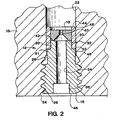
- a nozzle assembly 12 is shown in Figure 2 installed in housing means, namely cutting head 10, comprises three parts: nozzle body means, namely set screw 16; jet forming means for forming a liquid cutting jet, namely nozzle 18, and sealing mens, namely sleeve 20.
- Cutting head 10 defines a nozzle supply passage 22 and a threaded bore 24.
- Set screw 16 has a threaded shank 26 sized to threadedly engage bore 24; a first snout 28 of a diameter smaller than the diameter of the nozzle supply passage 22 to permit its entry therein; a second snout 30, smaller in diameter than first snout 28 and terminating in a flat upstream surface 32; a longitudinal bore 34 passing therethrough; a drive recess 36 for being engaged by a drive means, a shoulder 31 formed by the upstream face of first snout 28, and a peripheral corner 33 of shoulder 31.
- Nozzle 18 defines a longitudinal bore 40 and a flat surface 42.
- Sleeve 20 is tubular, and has a peripheral chamfer 46 on its upstream end 44.
- Nozzle assembly 12 is assembled by first placing sleeve 20 over the end of second snout 30, so its downstream end 47 is seated on shoulder 31.
- the nozzle 18 is then inserted into sleeve 20 until its flat surface 42 is firmly against flat surface 32 of set screw 16.
- Flat surfaces 42,32 form a seal therebetween, while the sleeve 20 seals the peripheries of nozzle 18 and second snout 30.
- sleeve 20 Since the internal diameter of sleeve 20 is about the same as, or slightly smaller than the diameter of snout 30 and nozzle 18, it will be appreciated that the sleeve 20 grips both snout 30 and nozzle 18 in a relatively firm friction and/or elastic grip, thereby holding the nozzle assembly 12 together in an assembled relation so it can be handled conveniently as a unit.
- sleeve 20 is shown extending upstream from shoulder 31 past the upstream face of nozzle 18, it need not necessarily do so.
- nozzle 18 could be held in place on set screw 16 by other means such as, for example, with an adhesive and/or by providing a recess in the upstream face 32 of second snout 30 sized to receive nozzle 18.
- sleeve 20 could be a much shorter length and extend upstream from shoulder 31 only a short distance, for example, below or up to the level of the upstream face 32 of the second snout 30.
- the outer diameter of sleeve 20, when assembled as part of nozzle assembly 12, and prior to insertion into nozzle supply passage 22 in cutting head 20, is preferably slightly larger than the diameter of passage 22, and the upstream end 44 of sleeve 20 preferably extends a short distance past nozzle 18, but it need not do so, for the reasons set out below.
- Nozzle supply passage 22, sleeve 20, nozzle 18 and set screw 16 are preferably symmetrical about their longitudinal axes and are of circular cross-sectional configurations, but they need not be.
- Bore 40 in nozzle 18, bore 34 in set screw 16, and drive recess 36 are preferably axially aligned, though they need not be as long as the fluid jet passing, during operation, through bore 34 is not interfered with as it travels through and exits nozzle assembly 12.
- Drive recess 36 preferably is sized to be driveable by any conventional drive means such as an allen wrench or screwdriver, but it could assume other configurations so as to be driven by some other tool.
- Drive recess 36 need not be located on the longitudinal axis of set screw 16, in which case bore 34 of set screw 16 would extend to the downstream surface 48 of set screw 16.
- One working embodiment was tested at up to 60,000 psi and did not leak. The working fluid was water. There is no reason to believe it would leak at pressures above 60,000 psi.
- the cutting head 10 and set screw 16 are formed from materials, such as stainless steel, which are stron enough to withstand design operating pressures plus normal safety margins, and which are resistant to corrosion from the working fluid and operating environment.
- Nozzle 18 is formed from synthetic sapphire, but other materials could be used depending on the particular operating pressures and working fluids used.
- Sleeve 20 is formed from UHMW-PE (ultra-high molecular weight polyethylene). At working pressures higher than 60,000 psi, soft metals could be used, such as bronze or brass.
- nozzle supply passage 22 and first snout 28 have respective diametes of .125 and .124 inches, leaving a radial clearance of .0005 inches therebetween. A smaller clearance would be of advantage.
- First snout 28 extends into passage 22 .020 inches past the upstream end of threaded bore 24. Threaded bore 24 and the threaded shank 26 were about .160 inches in length and had at least three full threads, and preferably more, to prevent blowout of set screw 16 at operating pressure.
- Second snout 30 and nozzle 18 have a diameter of .078 inches, but this is not critical.
- Bore 40 in nozzle 18 has a diameter which is dictated by the particular job in hand, and typically runs from .005 to .025 inches.
- the diameter of bore 34 in set screw 16 is, as a rule of thumb, at least twice the diameter of bore 40.
- Second snout 30 extends .030 inches past shoulder 31 of first snout 28, but this dimension is not critical.
- the external diameter of sleeve 20, prior to assembly is .125 inches -- the same as the diameter of supply passage 22.
- Sleeve 20's internal diameter, prior to assembly, is 0.76 inches -- .002 inches smaller in diameter than snout 30 and nozzle 18, which it is designed to receive.
- sleeve 20 snugly holds nozzle assembly 12 firmly assembled.
- the external diameter of the sleeve 20 increases by about .002 inches, as the snout 30 and nozzle 18 are inserted into sleeve 20 which has an undersized internal diameter -making the external diameter of the sleeve 20, when assembled, about .002 inches greater in diameter than supply passage 22.
- the upstream end of sleeve 20 extends .010 to .015 inches past the upstream end of nozzle 18.
- this sizing of sleeve 20 serves triple purposes and solves three problems at the same time. That is, it holds sleeve 20, nozzle 18, and second snout 30 in an assembled relation, it forms a good seal therebetween, and it provides for the necessary oversizing of sleeve 20 as compared to passage 30 to effectuate a good seal therebetween also.
- sleeve 20 makes the internal diameter of sleeve 20 about the same as or slightly greater than the external diameter of nozzle 18 and second snout 30, and using a friction fit and/or adhesive to hold them together and form a seal therebetween. Then sleeve 20 could be made with the necessary oversize external diameter for a good seal with passage 22.
- the internal diameter of the threaded bore 24 in cutting head 10 is larger than the assembled external diameter of the sleeve 20 to prevent interference therewith when nozzle assembly 12 is being assembled with cutting head 10.
- nozzle assembly 12 is screwed into head 10 from the exterior of head 10 by applying a drive tool to drive recess 36 of set screw 16; the chamfer 46 on sleeve 20 aiding in insertion of the oversize sleeve 20 into supply passage 22.
- a drive tool to drive recess 36 of set screw 16
- the chamfer 46 on sleeve 20 aiding in insertion of the oversize sleeve 20 into supply passage 22.
- the sleeve 20 and nozzle 18, which are inexpensive enough to be considered throw-away items; are blown out of the supply passage 22 by pressurising the fluid therein, although they could be caught and saved for examination, repair or possible re-use, if desired.
- supply passage 22 is connected to any suitable source of working fluid at the desired operating pressure.
- the working fluid forces the flat surfaces 42,32 of nozzle 18 and second snout 30 tightly together, forming a seal therebetween.
- the working fluid also bears against the upstream end 44 of sleeve 20, thereby tending to force sleeve 20 downstream until sleeve 20 seats and seals against shoulder 31.
- the sleeve 20 then tends to swell radially, both inwardly and outwardly, thereby firmly sealing against nozzle supply passage 22, second snout 30, and nozzle 18. It is important to note that the seals between sleeve 20 and shoulder 31, nozzle 18, second snout 30 and passage 22 grow tighter and more effective as the working fluid pressure increases.
- sleeve 20 Since the sleeve 20 tends to flow plastically under the working pressure, it will seal effectively even if the surfaces it contacts are scratched or irregular. In time, sleeve 20 will tend very gradually to flow through the very small clearance between first snout 28 and supply passage 22, but since such flow would be very slow, and since the upstream end 44 of sleeve 20 was chosen to extend past nozzle 18, sleeve 20 has a longitudinal length sufficient to compensate for any such downstream flow during the design life of nozzle assembly 12. Increased design life is easily achieved by either making sleeve 20 thicker, longer, or from a material which flows less under pressure than UHMW-PE or by reducing the clearance between first snout 28 and passage 22.
- FIG 3 The embodiment of Figure 3, is identical to that shown in Figure 2 except as described below, and so that same parts are referredto by the same reference numerals but with a prime appended thereto.
- a chamfer 50 has been provided on an enlarged snout 28'.
- the chamfer 50 of first snout 28' engages corner 52 on passageway 22' so preventing any tendency of sleeve 20' to flow downstream under working pressure past corner 52 of passage 22'.
- a chamfer could be provided at the upstream end of threaded bore 24, and first snout 28 could be enlarged and have a square corner 33 adapted to engage such a chamfer when set screw 16 is tightened down to achieve the same end.
Landscapes
- Engineering & Computer Science (AREA)
- Life Sciences & Earth Sciences (AREA)
- Mining & Mineral Resources (AREA)
- Geology (AREA)
- Mechanical Engineering (AREA)
- Physics & Mathematics (AREA)
- Fluid Mechanics (AREA)
- General Life Sciences & Earth Sciences (AREA)
- Environmental & Geological Engineering (AREA)
- Geochemistry & Mineralogy (AREA)
- General Engineering & Computer Science (AREA)
- Architecture (AREA)
- Forests & Forestry (AREA)
- Nozzles (AREA)
- Perforating, Stamping-Out Or Severing By Means Other Than Cutting (AREA)
- Special Spraying Apparatus (AREA)
- Turbine Rotor Nozzle Sealing (AREA)
- Fuel-Injection Apparatus (AREA)
Priority Applications (1)
| Application Number | Priority Date | Filing Date | Title |
|---|---|---|---|
| AT84307622T ATE42384T1 (de) | 1983-11-08 | 1984-11-05 | Leckfreie schneidduesen-einheit fuer fluessigkeiten hohen druckes und hoher geschwindigkeit. |
Applications Claiming Priority (2)
| Application Number | Priority Date | Filing Date | Title |
|---|---|---|---|
| US55023283A | 1983-11-08 | 1983-11-08 | |
| US550232 | 1983-11-08 |
Publications (3)
| Publication Number | Publication Date |
|---|---|
| EP0146252A2 true EP0146252A2 (fr) | 1985-06-26 |
| EP0146252A3 EP0146252A3 (en) | 1985-08-07 |
| EP0146252B1 EP0146252B1 (fr) | 1989-04-19 |
Family
ID=24196271
Family Applications (1)
| Application Number | Title | Priority Date | Filing Date |
|---|---|---|---|
| EP84307622A Expired EP0146252B1 (fr) | 1983-11-08 | 1984-11-05 | Montage d'une buse de coupe à jet de fluide, à haute pression et grande vitesse, sans fuite |
Country Status (8)
| Country | Link |
|---|---|
| EP (1) | EP0146252B1 (fr) |
| JP (1) | JPS60168558A (fr) |
| KR (1) | KR850004141A (fr) |
| AT (1) | ATE42384T1 (fr) |
| AU (1) | AU3499784A (fr) |
| CA (1) | CA1248008A (fr) |
| DE (1) | DE3477831D1 (fr) |
| ZA (1) | ZA848626B (fr) |
Cited By (7)
| Publication number | Priority date | Publication date | Assignee | Title |
|---|---|---|---|---|
| EP0225082A3 (fr) * | 1985-11-16 | 1988-07-27 | Nl Petroleum Products Limited | Trépan de forage rotatif |
| FR2643291A1 (fr) * | 1989-02-23 | 1990-08-24 | Lediabat Frederic | Perfectionnement aux dispositifs pour la projection de jets de liquide a des fins de nettoyage et/ou de decoupe |
| EP0398405A1 (fr) * | 1989-05-16 | 1990-11-22 | Schneider, Francine | Méthode à deux jets |
| FR2681372A1 (fr) * | 1991-09-16 | 1993-03-19 | Total Sa | Duse divergente pour outil de forage, et outil utilisant une telle duse. |
| FR2802835A1 (fr) * | 1999-12-22 | 2001-06-29 | Sundholm Goeran | Tete de pulverisation, notamment pour la lutte contre l'incendie |
| CN105003204A (zh) * | 2015-08-05 | 2015-10-28 | 重庆大学 | 煤层气开采物理模拟试验用冲孔装置 |
| CN107763615A (zh) * | 2016-08-19 | 2018-03-06 | 河南汇金智能装备有限公司 | 油枪 |
Families Citing this family (1)
| Publication number | Priority date | Publication date | Assignee | Title |
|---|---|---|---|---|
| DE102005025583B4 (de) * | 2004-06-09 | 2006-11-23 | Oskar Moser Technische Edelsteine Gmbh | Wasserstrahl-Reinigungsdüse |
Family Cites Families (4)
| Publication number | Priority date | Publication date | Assignee | Title |
|---|---|---|---|---|
| US3750961A (en) * | 1971-07-16 | 1973-08-07 | N Franz | Very high velocity fluid jet nozzles and methods of making same |
| GB1517769A (en) * | 1975-12-24 | 1978-07-12 | British Hydromechanics | Nozzle member for a liquid jet cutting apparatus |
| GB1547769A (en) * | 1976-08-27 | 1979-06-27 | Smiths Industries Ltd | Indicating instruments |
| US4306627A (en) * | 1977-09-22 | 1981-12-22 | Flow Industries, Inc. | Fluid jet drilling nozzle and method |
-
1984
- 1984-11-05 EP EP84307622A patent/EP0146252B1/fr not_active Expired
- 1984-11-05 ZA ZA848626A patent/ZA848626B/xx unknown
- 1984-11-05 DE DE8484307622T patent/DE3477831D1/de not_active Expired
- 1984-11-05 AU AU34997/84A patent/AU3499784A/en not_active Abandoned
- 1984-11-05 CA CA000467082A patent/CA1248008A/fr not_active Expired
- 1984-11-05 AT AT84307622T patent/ATE42384T1/de active
- 1984-11-08 JP JP59235915A patent/JPS60168558A/ja active Pending
- 1984-11-08 KR KR1019840006987A patent/KR850004141A/ko not_active Withdrawn
Cited By (11)
| Publication number | Priority date | Publication date | Assignee | Title |
|---|---|---|---|---|
| EP0225082A3 (fr) * | 1985-11-16 | 1988-07-27 | Nl Petroleum Products Limited | Trépan de forage rotatif |
| FR2643291A1 (fr) * | 1989-02-23 | 1990-08-24 | Lediabat Frederic | Perfectionnement aux dispositifs pour la projection de jets de liquide a des fins de nettoyage et/ou de decoupe |
| EP0398405A1 (fr) * | 1989-05-16 | 1990-11-22 | Schneider, Francine | Méthode à deux jets |
| WO1990014200A1 (fr) * | 1989-05-16 | 1990-11-29 | Schneider, Francine | Procede a double jet |
| TR25327A (tr) * | 1989-05-16 | 1993-01-01 | Schneider Francine | Madde cikarma calismasi icin yöntem ve tertibat |
| FR2681372A1 (fr) * | 1991-09-16 | 1993-03-19 | Total Sa | Duse divergente pour outil de forage, et outil utilisant une telle duse. |
| EP0533550A1 (fr) * | 1991-09-16 | 1993-03-24 | TOTAL Société anonyme dite : | Duse divergente pour outil de forage, et outil utilisant une telle duse |
| US5293946A (en) * | 1991-09-16 | 1994-03-15 | Total | Divergent fluid nozzle for drilling tool |
| FR2802835A1 (fr) * | 1999-12-22 | 2001-06-29 | Sundholm Goeran | Tete de pulverisation, notamment pour la lutte contre l'incendie |
| CN105003204A (zh) * | 2015-08-05 | 2015-10-28 | 重庆大学 | 煤层气开采物理模拟试验用冲孔装置 |
| CN107763615A (zh) * | 2016-08-19 | 2018-03-06 | 河南汇金智能装备有限公司 | 油枪 |
Also Published As
| Publication number | Publication date |
|---|---|
| ZA848626B (en) | 1985-06-26 |
| CA1248008A (fr) | 1989-01-03 |
| KR850004141A (ko) | 1985-07-01 |
| DE3477831D1 (en) | 1989-05-24 |
| EP0146252A3 (en) | 1985-08-07 |
| EP0146252B1 (fr) | 1989-04-19 |
| JPS60168558A (ja) | 1985-09-02 |
| AU3499784A (en) | 1985-05-16 |
| ATE42384T1 (de) | 1989-05-15 |
Similar Documents
| Publication | Publication Date | Title |
|---|---|---|
| US4660773A (en) | Leakproof high pressure nozzle assembly | |
| US6312199B1 (en) | Cutting tool | |
| US7273331B2 (en) | Boring bar having internal coolant supply | |
| EP0146252A2 (fr) | Montage d'une buse de coupe à jet de fluide, à haute pression et grande vitesse, sans fuite | |
| CN104768682A (zh) | 带具有可压缩部件的内部冷却剂通路的切削工具座 | |
| CA2007377A1 (fr) | Accouplement de conduits de fluide | |
| CN1115566A (zh) | 用于机床的夹具 | |
| US5316037A (en) | Valve for insertion in a pressurized fluid flow line | |
| US7306238B2 (en) | Collet and lock nut | |
| JP2002321111A (ja) | 深穴切削装置 | |
| AU673319B1 (en) | In-line valve for insertion in a pressurized fluid flow line | |
| US20060029480A1 (en) | Tool holder assembly | |
| US5911421A (en) | Sealed collet having improved radial flexibility for facilitating removal from a locknut | |
| EP0295868B1 (fr) | Dispositif de buse pour un système de coupage à jet de liquide | |
| US8827610B2 (en) | Hydraulic coupling system for coupling a shell mill to an adapter | |
| US20060013665A1 (en) | Tool holder assembly | |
| GB2266676A (en) | Tool-holder with coolant groove | |
| JPH0224992B2 (fr) | ||
| US6491057B1 (en) | Method and device for installing an air tap onto a pressurized air pipe | |
| US4611672A (en) | Drill bit | |
| US7144207B2 (en) | Fluid chuck device and method | |
| JP6810221B1 (ja) | モジュラーボーリングシステム | |
| US5119680A (en) | Transducer mounting apparatus | |
| JP3016266U (ja) | 切削工具 | |
| US4288114A (en) | Fitting with biased locking device for coupling pipes |
Legal Events
| Date | Code | Title | Description |
|---|---|---|---|
| PUAI | Public reference made under article 153(3) epc to a published international application that has entered the european phase |
Free format text: ORIGINAL CODE: 0009012 |
|
| PUAL | Search report despatched |
Free format text: ORIGINAL CODE: 0009013 |
|
| AK | Designated contracting states |
Designated state(s): AT BE CH DE FR GB IT LI LU NL SE |
|
| AK | Designated contracting states |
Designated state(s): AT BE CH DE FR GB IT LI LU NL SE |
|
| 17P | Request for examination filed |
Effective date: 19860120 |
|
| 17Q | First examination report despatched |
Effective date: 19870401 |
|
| GRAA | (expected) grant |
Free format text: ORIGINAL CODE: 0009210 |
|
| AK | Designated contracting states |
Kind code of ref document: B1 Designated state(s): AT BE CH DE FR GB IT LI LU NL SE |
|
| REF | Corresponds to: |
Ref document number: 42384 Country of ref document: AT Date of ref document: 19890515 Kind code of ref document: T |
|
| REF | Corresponds to: |
Ref document number: 3477831 Country of ref document: DE Date of ref document: 19890524 |
|
| ET | Fr: translation filed | ||
| ITF | It: translation for a ep patent filed | ||
| PG25 | Lapsed in a contracting state [announced via postgrant information from national office to epo] |
Ref country code: AT Effective date: 19891105 |
|
| PG25 | Lapsed in a contracting state [announced via postgrant information from national office to epo] |
Ref country code: SE Effective date: 19891106 |
|
| PG25 | Lapsed in a contracting state [announced via postgrant information from national office to epo] |
Ref country code: LU Free format text: LAPSE BECAUSE OF NON-PAYMENT OF DUE FEES Effective date: 19891130 Ref country code: LI Effective date: 19891130 Ref country code: CH Effective date: 19891130 Ref country code: BE Effective date: 19891130 |
|
| PGFP | Annual fee paid to national office [announced via postgrant information from national office to epo] |
Ref country code: GB Payment date: 19891130 Year of fee payment: 6 Ref country code: FR Payment date: 19891130 Year of fee payment: 6 |
|
| PGFP | Annual fee paid to national office [announced via postgrant information from national office to epo] |
Ref country code: DE Payment date: 19900129 Year of fee payment: 6 |
|
| PLBE | No opposition filed within time limit |
Free format text: ORIGINAL CODE: 0009261 |
|
| STAA | Information on the status of an ep patent application or granted ep patent |
Free format text: STATUS: NO OPPOSITION FILED WITHIN TIME LIMIT |
|
| 26N | No opposition filed | ||
| BERE | Be: lapsed |
Owner name: FLOW INDUSTRIES INC. Effective date: 19891130 |
|
| PG25 | Lapsed in a contracting state [announced via postgrant information from national office to epo] |
Ref country code: NL Effective date: 19900601 |
|
| NLV4 | Nl: lapsed or anulled due to non-payment of the annual fee | ||
| REG | Reference to a national code |
Ref country code: CH Ref legal event code: PL |
|
| PG25 | Lapsed in a contracting state [announced via postgrant information from national office to epo] |
Ref country code: GB Effective date: 19901105 |
|
| GBPC | Gb: european patent ceased through non-payment of renewal fee | ||
| PG25 | Lapsed in a contracting state [announced via postgrant information from national office to epo] |
Ref country code: FR Effective date: 19910731 |
|
| PG25 | Lapsed in a contracting state [announced via postgrant information from national office to epo] |
Ref country code: DE Effective date: 19910801 |
|
| REG | Reference to a national code |
Ref country code: FR Ref legal event code: ST |
|
| EUG | Se: european patent has lapsed |
Ref document number: 84307622.5 Effective date: 19900705 |