EP0146262B1 - Amplificateurs optiques - Google Patents
Amplificateurs optiques Download PDFInfo
- Publication number
- EP0146262B1 EP0146262B1 EP84307907A EP84307907A EP0146262B1 EP 0146262 B1 EP0146262 B1 EP 0146262B1 EP 84307907 A EP84307907 A EP 84307907A EP 84307907 A EP84307907 A EP 84307907A EP 0146262 B1 EP0146262 B1 EP 0146262B1
- Authority
- EP
- European Patent Office
- Prior art keywords
- fibre
- optical
- signal
- wavelength
- pump
- Prior art date
- Legal status (The legal status is an assumption and is not a legal conclusion. Google has not performed a legal analysis and makes no representation as to the accuracy of the status listed.)
- Expired - Lifetime
Links
Images


Classifications
-
- H—ELECTRICITY
- H01—ELECTRIC ELEMENTS
- H01S—DEVICES USING THE PROCESS OF LIGHT AMPLIFICATION BY STIMULATED EMISSION OF RADIATION [LASER] TO AMPLIFY OR GENERATE LIGHT; DEVICES USING STIMULATED EMISSION OF ELECTROMAGNETIC RADIATION IN WAVE RANGES OTHER THAN OPTICAL
- H01S3/00—Lasers, i.e. devices using stimulated emission of electromagnetic radiation in the infrared, visible or ultraviolet wave range
- H01S3/30—Lasers, i.e. devices using stimulated emission of electromagnetic radiation in the infrared, visible or ultraviolet wave range using scattering effects, e.g. stimulated Brillouin or Raman effects
- H01S3/302—Lasers, i.e. devices using stimulated emission of electromagnetic radiation in the infrared, visible or ultraviolet wave range using scattering effects, e.g. stimulated Brillouin or Raman effects in an optical fibre
-
- H—ELECTRICITY
- H01—ELECTRIC ELEMENTS
- H01S—DEVICES USING THE PROCESS OF LIGHT AMPLIFICATION BY STIMULATED EMISSION OF RADIATION [LASER] TO AMPLIFY OR GENERATE LIGHT; DEVICES USING STIMULATED EMISSION OF ELECTROMAGNETIC RADIATION IN WAVE RANGES OTHER THAN OPTICAL
- H01S3/00—Lasers, i.e. devices using stimulated emission of electromagnetic radiation in the infrared, visible or ultraviolet wave range
- H01S3/30—Lasers, i.e. devices using stimulated emission of electromagnetic radiation in the infrared, visible or ultraviolet wave range using scattering effects, e.g. stimulated Brillouin or Raman effects
- H01S3/307—Lasers, i.e. devices using stimulated emission of electromagnetic radiation in the infrared, visible or ultraviolet wave range using scattering effects, e.g. stimulated Brillouin or Raman effects in a liquid
Definitions
- This invention relates to optical amplifiers, and in particular to means and methods for amplifying an optical signal without having to convert it to an electrical signal.
- an optical amplifier comprising a length of optical fibre; a semiconductor laser and drive means therefor, the output of the semiconductor laser. comprising a pulsed pump signal; and coupler means having an input for an optical signal, of a first wavelength, to be amplified, an input for the pump signal and an output coupled to an input end of the optical fibre, and wherein in use the fibre is optically pumped by the pump signal at a second wavelength and gain is obtained due to Raman stimulated emission, at the first wavelength in the signal to be amplified, which first wavelength corresponds to one or more Stokes shift (s) from the pump signal.
- s Stokes shift
- a method of amplifying a first optical signal of a first wavelength comprising the steps of generating a pulsed pump signal at a second wavelength by means of a semiconductor laser, and synchronously coupling the first optical signal and the pump signal into a length of optical fibre, the first wavelength corresponding to one Stokes shift from the pump signal wavelength, Raman stimulated emission in the optical fibre serving to induce gain in the first optical signal.
- optical fibre communications systems A major factor in the design of optical fibre communications systems is the necessity to employ signal repeaters (regenerators) at intervals. If, however, the optical signal can be amplified optically by applying a pump signal to induce stimulated Raman scattering at an end of the link the length of the link between any necessary regenerators can be greatly extended.
- the amplification results mentioned above for 1.064 micron and 1.24 micron were based on the use of a pump signal provided by a Q-switched YAG (yttrium aluminium garnet) laser and GeO2 doped SiO2 single mode fibres at power levels in the vicinity of a stimulated Raman scattering threshold power of 1.2W, and 0.5 to 5W (a forward Raman gain of 45 dB being measured at 2W), respectively.
- a pump signal provided by a Q-switched YAG (yttrium aluminium garnet) laser and GeO2 doped SiO2 single mode fibres at power levels in the vicinity of a stimulated Raman scattering threshold power of 1.2W, and 0.5 to 5W (a forward Raman gain of 45 dB being measured at 2W), respectively.
- FIG. 1 A schematic arrangement of the equipment employed is shown in Fig. 1.
- a Q-switched neodymium doped YAG laser 1 emitting at 1.06 micron was employed to pump a Raman fibre laser comprised by a low-loss 80 m length of single mode GeO2 doped SiO2 optical fibre 2 having a core diameter of 5.1 micron and an index difference of 1.3x10 -2 .
- the spectral output from the fibre 2 consisted of five orders of Stokes' emission at wavelengths of 1.12, 1.18, 1.24, 1.30 and 1.36 micron.
- a small fraction of the output from fibre 2 was split off by an uncoated glass plate 3 to provide a signal for amplification in a second fibre 4.
- the wavelength ⁇ s of the signal for amplification was selected by a monochromator 5 before being transmitted via an optical path including mirrors M1 and M2, and focussed into amplifier fibre 4 via a second glass plate 6.
- the wavelength ⁇ p of the pump signal to the amplifier fibre 2 was selected by a monochromator 7.
- the pump signal and the signal for amplification were synchronously focussed into the amplifier fibre 4.
- a monochromator 8 coupled to the output end of amplifier fibre 4 was tuned to the signal wavelength ⁇ s and the transmitted pulse observed on an oscilloscope 9 after detection by a germanium avalanche photodiode 10.
- the amplifier fibre 4 was comprised by a 3 km length of GeO2 doped SiO2 single mode fibre having a core diameter of 8 micron and an index difference of 4.6x10 -3 .
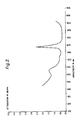
- the loss curve for this fibre is shown in Fig. 2.
- the minium attenuation is at 1550 nm (0.27 dB/km), whereas at 1300 nm the attenuation is 0.41 db/km.
- the fibre material dispersion reaches zero and there is a very high band width potential at this wavelength.
- Early transmission studies generally employed wavelengths of the order of 850 nm, which Fig. 2 indicates as having a fibre loss of the order of 2dB/km, however present studies are based on 1300 or 1500 nm due to the significantly lower losses at these wavelengths.
- gain in the amplifier fibre 4 was observed at all of the Stokes orders emerging from Raman laser fibre 2 by pumping at the wavelength corresponding to the preceding Stokes order.
- the transmitted pulse was observed with and without the presence of the pump signal.
- pumping was also performed at a wavelength corresponding to two preceding Stokes orders. Owing to the efficient generation of multiple or Stokes lines in the Raman fibre laser 2, when the stimulated emission threshold is exceeded for each order, power from the preceding order is depleted.
- the amplification factor of the fibre 4 was defined as the ratio of the output signal pulse with and without the presence of the pump signal.
- the amplified output contained a contribution from stimulated Raman emission due to the pump alone and allowance for this was made in determining the amplification factor. Results obtained are summarised in Table 1.
- YAG lasers are not suitable for use as the pumps.
- pump power launched into the amplifier was measured at a pump wavelength of 1.30 micron and an amplification of 5 dB was observed at a signal wavelength of 1.36 micron.
- the peak power emerging from a short cladding-mode-stripped length of the amplifier was measured using an Anritsu ML93A calibrated power meter and found to be as low as 80 mW.
- optimised launch and drive conditions amplification is possible with pump sources comprised by semiconductor lasers, for example GaInAsP for use in the range 1.0 to 1.8 micron or lead salt for mid I.R. applications.
- the amplifier fibre requires, for optimum amplification performance, to have a high Raman cross-section, and a low transmission loss.
- GeO2 doped SiO2 fibre has a high Raman cross-section (depending on the amount of GeO2 dopant) in comparison with undoped SiO2 fibre, however pure GeO2 fibre has a Raman cross-section ten times higher than undoped SiO2 fibre, although the transmission losses are higher than for undoped SiO2 fibre.
- the Raman cross-section is 2400 times greater than for undoped SiO2 fibre.
- an optical amplifier with the basic structure illustrated in Fig. 4. It comprises a semiconductor laser 11 with appropriate drive circuitry to provide a pulsed output and used as a pump, a coupler 12 wherein an optical signal 13 to be amplified is coupled with a pump signal 14 output from laser 11 and a length of optical fibre comprising an amplifier fibre 15.
- the wavelengths ( ⁇ s ) of the signal 13 is, preferably, one Stokes shift away from that of the pump signal 14 ( ⁇ p ).
- the amplifier fibre 15 is of a length, loss and material appropriate to operating requirements and is designed accordingly.
- the signal to be amplified is of the order of 450 cm -1 away from the pump signal.
- the pump signal as applied to the coupler 12 is of a greater power than the signal to be amplified, the materials from which the fibre is made determining the required pump power.
- the signal 16 output from fibre 15 is signal 13 as amplified.
Landscapes
- Physics & Mathematics (AREA)
- Electromagnetism (AREA)
- Engineering & Computer Science (AREA)
- Plasma & Fusion (AREA)
- Optics & Photonics (AREA)
- Lasers (AREA)
- Optical Communication System (AREA)
- Semiconductor Lasers (AREA)
- Led Devices (AREA)
Claims (9)
- Amplificateur optique, comprenant un tronçon de fibre optique (15), un laser à semi-conducteur et un dispositif (11) de pilotage du laser, le signal de sortie du laser à semi-conducteur étant un signal pulsé (14) de pompage, et un dispositif coupleur (12) ayant une entrée d'un signal optique (13) à une première longueur d'onde, ce signal étant destiné à être amplifié, une entrée d'un signal de pompage (14) et une sortie couplée à une extrémité d'entrée de la fibre optique (15), et dans lequel, pendant l'utilisation, la fibre (15) subit un pompage optique par le signal de pompage (14) à une seconde longueur d'onde et un gain est obtenu par émission Raman stimulée à la première longueur d'onde dans le signal (13) à amplifier, cette première longueur d'onde correspondant au décalage d'un ou plusieurs ordres de Stokes par rapport au signal de pompage (14).
- Amplificateur optique selon la revendication 1,
caractérisé en ce que la fibre optique (15) a une section Raman élevée et de faibles pertes de transmission. - Amplificateur optique selon la revendication 1,
caractérisé en ce que la fibre optique (15) est une fibre monomode de SiO₂ dopée par GeO₂. - Amplificateur optique selon la revendication 1,
caractérisé en ce que la fibre optique (15) est formée de GeO₂ pur. - Amplificateur à fibre optique selon l'une quelconque des revendications précédentes, caractérisé en ce que le laser à semi-conducteur est formé de GaInAsP destiné à être utilisé dans la plage allant de 1,0 à 1,8 µm, ou d'un sel de plomb dans les applications dans l'infrarouge moyen.
- Procédé d'amplification d'un premier signal optique (13) à une première longueur d'onde, comprenant les étapes de création d'un signal pulsé de pompage (14) à une seconde longueur d'onde à l'aide d'un laser à semi-conducteur (11), et le couplage synchrone (12) du premier signal optique et du signal de pompage dans un tronçon de fibre optique (15), la première longueur d'onde correspondant à un décalage d'un ordre de Stokes par rapport à la longueur d'onde du signal de pompage, l'émission stimulée Raman dans la fibre optique ayant pour rôle d'induire un gain du premier signal optique.
- Procédé selon la revendication 6, caractérisé en ce que la fibre optique (15) a une section Raman élevée et de faibles pertes de transmission.
- Procédé selon la revendication 6, caractérisé en ce que la fibre optique (15) est formée d'une fibre de SiO₂ non dopé, d'une fibre de SiO₂ dopé par GeO₂ ou d'une fibre de GeO₂ pur.
- Procédé selon la revendication 6, caractérisé en ce que le laser à semi-conducteur (11) est formé de GaInAsP.
Priority Applications (1)
| Application Number | Priority Date | Filing Date | Title |
|---|---|---|---|
| AT84307907T ATE62359T1 (de) | 1983-12-16 | 1984-11-14 | Optische verstaerker. |
Applications Claiming Priority (2)
| Application Number | Priority Date | Filing Date | Title |
|---|---|---|---|
| GB8333610 | 1983-12-16 | ||
| GB08333610A GB2151868B (en) | 1983-12-16 | 1983-12-16 | Optical amplifiers |
Publications (3)
| Publication Number | Publication Date |
|---|---|
| EP0146262A2 EP0146262A2 (fr) | 1985-06-26 |
| EP0146262A3 EP0146262A3 (en) | 1987-06-10 |
| EP0146262B1 true EP0146262B1 (fr) | 1991-04-03 |
Family
ID=10553419
Family Applications (1)
| Application Number | Title | Priority Date | Filing Date |
|---|---|---|---|
| EP84307907A Expired - Lifetime EP0146262B1 (fr) | 1983-12-16 | 1984-11-14 | Amplificateurs optiques |
Country Status (9)
| Country | Link |
|---|---|
| US (1) | US4720684A (fr) |
| EP (1) | EP0146262B1 (fr) |
| JP (1) | JPS60145694A (fr) |
| AT (1) | ATE62359T1 (fr) |
| AU (1) | AU570520B2 (fr) |
| CA (1) | CA1245328A (fr) |
| DE (1) | DE3484388D1 (fr) |
| GB (1) | GB2151868B (fr) |
| ZA (1) | ZA849202B (fr) |
Families Citing this family (23)
| Publication number | Priority date | Publication date | Assignee | Title |
|---|---|---|---|---|
| US4554510A (en) * | 1983-09-12 | 1985-11-19 | The Board Of Trustees Of Leland Stanford Junior University | Switching fiber optic amplifier |
| GB2151869B (en) * | 1983-12-16 | 1986-12-31 | Standard Telephones Cables Ltd | Optical amplifiers |
| EP0186299B1 (fr) * | 1984-12-13 | 1990-04-18 | Stc Plc | Amplificateur optique |
| AU576678B2 (en) * | 1985-05-09 | 1988-09-01 | British Telecommunications Public Limited Company | Optical homodyne detection |
| CA1271065A (fr) * | 1985-07-24 | 1990-07-03 | Michael Charles Brierley | Dipositif dielectrique guide d'ondes optiques |
| AU584739B2 (en) * | 1985-08-13 | 1989-06-01 | British Technology Group Limited | Optical fibres |
| FR2586306B1 (fr) * | 1985-08-13 | 1988-08-12 | Grosso Philippe | Dispositif d'amplification de puissance lumineuse comportant une boucle a recirculation |
| US4790619A (en) * | 1986-04-25 | 1988-12-13 | American Telephone And Telegraph Company, At&T Bell Laboratories | Apparatus comprising Raman-active optical fiber |
| JPH0727149B2 (ja) * | 1986-11-04 | 1995-03-29 | 沖電気工業株式会社 | 光結合器 |
| JP2785285B2 (ja) * | 1988-12-01 | 1998-08-13 | 日本電気株式会社 | レーザ光検出装置 |
| US5083874A (en) * | 1989-04-14 | 1992-01-28 | Nippon Telegraph And Telephone Corporation | Optical repeater and optical network using the same |
| GB2249682B (en) * | 1990-11-09 | 1995-03-29 | Stc Plc | Optical amplifiers |
| DE69637562D1 (de) * | 1995-03-20 | 2008-07-24 | Fujitsu Ltd | Verfahren und Vorrichtung zur optischen Signalverarbeitung |
| GB9604281D0 (en) * | 1996-02-29 | 1996-05-01 | Stc Submarine Systems Ltd | A fibre raman laser for converting wavelengths or a broadband raman optical amplifier |
| US5790300A (en) * | 1996-10-15 | 1998-08-04 | Mcdonnell Douglas Corporation | Multi-channel fiber amplification system and associated method |
| US6760148B2 (en) | 1998-03-24 | 2004-07-06 | Xtera Communications, Inc. | Nonlinear polarization amplifiers in nonzero dispersion shifted fiber |
| US6101024A (en) | 1998-03-24 | 2000-08-08 | Xtera Communications, Inc. | Nonlinear fiber amplifiers used for a 1430-1530nm low-loss window in optical fibers |
| US6693737B2 (en) | 1998-03-24 | 2004-02-17 | Xtera Communications, Inc. | Dispersion compensating nonlinear polarization amplifiers |
| US6181464B1 (en) * | 1998-12-01 | 2001-01-30 | Tycom (Us) Inc. | Low noise Raman amplifier employing bidirectional pumping and an optical transmission system incorporating same |
| EP1330056A1 (fr) * | 2002-01-16 | 2003-07-23 | Lucent Technologies Inc. | Méthode et système pour appliquer une amplification Raman à un dispostif de transmission |
| US20040042061A1 (en) * | 2002-08-30 | 2004-03-04 | Islam Mohammed N. | Controlling ASE in optical amplification stages implementing time modulated pump signals |
| FR2858421B1 (fr) * | 2003-07-29 | 2005-11-11 | Cit Alcatel | Fibre optique active pour amplification raman |
| FR2864358A1 (fr) * | 2003-12-18 | 2005-06-24 | Saint Louis Inst | Dispositif de generation d'un rayonnement laser dans l'infrarouge |
Family Cites Families (13)
| Publication number | Priority date | Publication date | Assignee | Title |
|---|---|---|---|---|
| US3290539A (en) * | 1963-09-16 | 1966-12-06 | Rca Corp | Planar p-nu junction light source with reflector means to collimate the emitted light |
| US3705992A (en) * | 1971-12-13 | 1972-12-12 | Bell Telephone Labor Inc | Broadband tunable raman-effect devices in optical fibers |
| US3873825A (en) * | 1973-05-09 | 1975-03-25 | Bell Telephone Labor Inc | Apparatus and systems using broad band radiation pulse source |
| JPS56134774A (en) * | 1980-03-26 | 1981-10-21 | Nec Corp | Manufacture of semiconductor device |
| US4616898A (en) * | 1980-03-31 | 1986-10-14 | Polaroid Corporation | Optical communication systems using raman repeaters and components therefor |
| JPS56165385A (en) * | 1980-05-26 | 1981-12-18 | Nec Corp | Device for generating high power multiwavelength light pulse |
| JPS56165437A (en) * | 1980-05-26 | 1981-12-19 | Kokusai Denshin Denwa Co Ltd <Kdd> | Optical repeating system for optical communication |
| US4394623A (en) * | 1981-01-27 | 1983-07-19 | Kurnit Norman A | Ring cavity for a raman capillary waveguide amplifier |
| US4389617A (en) * | 1981-03-13 | 1983-06-21 | The United States Of America As Represented By The United States Department Of Energy | Combination ring cavity and backward Raman waveguide amplifier |
| GB2116391B (en) * | 1982-02-25 | 1985-08-14 | Western Electric Co | Single-mode optical fibre telecommunication apparatus |
| US4515431A (en) * | 1982-08-11 | 1985-05-07 | The Board Of Trustees Of The Leland Stanford Junior University | Fiber optic amplifier |
| US4546476A (en) * | 1982-12-10 | 1985-10-08 | The Board Of Trustees Of The Leland Stanford Junior University | Fiber optic amplifier |
| GB2151869B (en) * | 1983-12-16 | 1986-12-31 | Standard Telephones Cables Ltd | Optical amplifiers |
-
1983
- 1983-12-16 GB GB08333610A patent/GB2151868B/en not_active Expired
-
1984
- 1984-11-14 DE DE8484307907T patent/DE3484388D1/de not_active Expired - Fee Related
- 1984-11-14 EP EP84307907A patent/EP0146262B1/fr not_active Expired - Lifetime
- 1984-11-14 AT AT84307907T patent/ATE62359T1/de not_active IP Right Cessation
- 1984-11-22 AU AU35799/84A patent/AU570520B2/en not_active Ceased
- 1984-11-26 ZA ZA849202A patent/ZA849202B/xx unknown
- 1984-12-03 CA CA000469211A patent/CA1245328A/fr not_active Expired
- 1984-12-11 JP JP59261657A patent/JPS60145694A/ja active Pending
-
1986
- 1986-07-22 US US06/888,274 patent/US4720684A/en not_active Expired - Lifetime
Also Published As
| Publication number | Publication date |
|---|---|
| EP0146262A3 (en) | 1987-06-10 |
| US4720684A (en) | 1988-01-19 |
| EP0146262A2 (fr) | 1985-06-26 |
| ZA849202B (en) | 1985-06-26 |
| ATE62359T1 (de) | 1991-04-15 |
| AU3579984A (en) | 1985-06-20 |
| JPS60145694A (ja) | 1985-08-01 |
| CA1245328A (fr) | 1988-11-22 |
| DE3484388D1 (de) | 1991-05-08 |
| GB2151868B (en) | 1986-12-17 |
| AU570520B2 (en) | 1988-03-17 |
| GB2151868A (en) | 1985-07-24 |
Similar Documents
| Publication | Publication Date | Title |
|---|---|---|
| EP0146262B1 (fr) | Amplificateurs optiques | |
| EP0540602B1 (fr) | Amplificateur de guide d'ondes optique | |
| JP2971561B2 (ja) | エルビウム ドープ ファイバー増幅器 | |
| JP2813145B2 (ja) | 光ファイバ増幅システム | |
| US5497265A (en) | High-power signals optical generator for telecommunication systems | |
| Khegai et al. | O-band bismuth-doped fiber amplifier with 67 nm bandwidth | |
| US7463411B2 (en) | Optical fiber amplifier | |
| JP3621220B2 (ja) | 光増幅器及び光導波構造 | |
| CN100349336C (zh) | 多级拉曼放大器 | |
| Donodin et al. | 38 dB gain E-band bismuth-doped fiber amplifier | |
| EP0149886A2 (fr) | Amplificateurs optique | |
| US7436583B2 (en) | Optical amplification fiber, optical amplifier module, optical communication system and optical amplifying method | |
| US6504647B1 (en) | Optical fiber amplifier, a method of amplifying optical signals, optical communications system | |
| Seo et al. | Simultaneous amplification at two wavelengths near 1300 nm in a 6.5-cm-long bismuth-doped silica glass | |
| EP1220381A2 (fr) | Fibre optique pour amplification optique et amplificateur a fibre optique | |
| JP2756510B2 (ja) | 広帯域ファイバレーザ媒質及びこれを用いた光増幅器 | |
| Segi et al. | Silica-based composite fiber amplifier with 1480-1560 nm seamless gain-band | |
| JP2003188445A (ja) | 光増幅器及び光増幅部品 | |
| KR100326151B1 (ko) | 신호 대 잡음비 성능이 향상된 라만 광섬유 증폭기 및 그 사용방법 | |
| CN1006582B (zh) | 光放大器 | |
| JP2025527256A (ja) | ビスマスドープファイバ増幅器のファイバレーザポンピング | |
| JP3268708B2 (ja) | 高出力光ファイバ増幅器 | |
| Giggenbach | Design of an optical fiber amplifier with multiple serial pumping for space communications | |
| Bi-EDFA | CHARACTERIZATION OF STIMULATED BRILLOUIN SCATTERING AND | |
| Auge et al. | Relevant Parameters Study For 1.55 µm Signal Amplification Using 1.48 µm Pumped Erbium-Doped Fibers |
Legal Events
| Date | Code | Title | Description |
|---|---|---|---|
| PUAI | Public reference made under article 153(3) epc to a published international application that has entered the european phase |
Free format text: ORIGINAL CODE: 0009012 |
|
| AK | Designated contracting states |
Designated state(s): AT BE CH DE FR IT LI LU NL SE |
|
| RAP1 | Party data changed (applicant data changed or rights of an application transferred) |
Owner name: STC PLC |
|
| RAP1 | Party data changed (applicant data changed or rights of an application transferred) |
Owner name: STC PLC |
|
| PUAL | Search report despatched |
Free format text: ORIGINAL CODE: 0009013 |
|
| PUAF | Information related to the publication of a search report (a3 document) modified or deleted |
Free format text: ORIGINAL CODE: 0009199SEPU |
|
| AK | Designated contracting states |
Kind code of ref document: A3 Designated state(s): AT BE CH DE FR IT LI LU NL SE |
|
| D17D | Deferred search report published (deleted) | ||
| PUAL | Search report despatched |
Free format text: ORIGINAL CODE: 0009013 |
|
| AK | Designated contracting states |
Kind code of ref document: A3 Designated state(s): AT BE CH DE FR IT LI LU NL SE |
|
| 17P | Request for examination filed |
Effective date: 19871112 |
|
| 17Q | First examination report despatched |
Effective date: 19891120 |
|
| ITF | It: translation for a ep patent filed | ||
| GRAA | (expected) grant |
Free format text: ORIGINAL CODE: 0009210 |
|
| AK | Designated contracting states |
Kind code of ref document: B1 Designated state(s): AT BE CH DE FR IT LI LU NL SE |
|
| PG25 | Lapsed in a contracting state [announced via postgrant information from national office to epo] |
Ref country code: SE Effective date: 19910403 Ref country code: LI Effective date: 19910403 Ref country code: CH Effective date: 19910403 Ref country code: BE Effective date: 19910403 Ref country code: AT Effective date: 19910403 |
|
| REF | Corresponds to: |
Ref document number: 62359 Country of ref document: AT Date of ref document: 19910415 Kind code of ref document: T |
|
| ET | Fr: translation filed | ||
| REF | Corresponds to: |
Ref document number: 3484388 Country of ref document: DE Date of ref document: 19910508 |
|
| REG | Reference to a national code |
Ref country code: CH Ref legal event code: PL |
|
| PG25 | Lapsed in a contracting state [announced via postgrant information from national office to epo] |
Ref country code: LU Free format text: LAPSE BECAUSE OF NON-PAYMENT OF DUE FEES Effective date: 19911130 |
|
| PLBE | No opposition filed within time limit |
Free format text: ORIGINAL CODE: 0009261 |
|
| STAA | Information on the status of an ep patent application or granted ep patent |
Free format text: STATUS: NO OPPOSITION FILED WITHIN TIME LIMIT |
|
| 26N | No opposition filed | ||
| PGFP | Annual fee paid to national office [announced via postgrant information from national office to epo] |
Ref country code: NL Payment date: 19931130 Year of fee payment: 10 |
|
| ITPR | It: changes in ownership of a european patent |
Owner name: CAMBIO RAGIONE SOCIALE;NORTHERN TELECOM EUROPE LIM |
|
| NLT1 | Nl: modifications of names registered in virtue of documents presented to the patent office pursuant to art. 16 a, paragraph 1 |
Owner name: STC LIMITED TE LONDEN, GROOT-BRITTANNIE. |
|
| NLT1 | Nl: modifications of names registered in virtue of documents presented to the patent office pursuant to art. 16 a, paragraph 1 |
Owner name: NORTHERN TELECOM EUROPE LIMITED TE LONDON, GROOT-B |
|
| REG | Reference to a national code |
Ref country code: FR Ref legal event code: TP |
|
| NLT1 | Nl: modifications of names registered in virtue of documents presented to the patent office pursuant to art. 16 a, paragraph 1 |
Owner name: STC LIMITED TE MAIDENHEAD, GROOT-BRITTANNIE. |
|
| NLS | Nl: assignments of ep-patents |
Owner name: NORTHERN TELECOM LIMITED IN MONTREAL, CANADA |
|
| PG25 | Lapsed in a contracting state [announced via postgrant information from national office to epo] |
Ref country code: NL Effective date: 19950601 |
|
| NLV4 | Nl: lapsed or anulled due to non-payment of the annual fee | ||
| PGFP | Annual fee paid to national office [announced via postgrant information from national office to epo] |
Ref country code: FR Payment date: 20011012 Year of fee payment: 18 |
|
| PGFP | Annual fee paid to national office [announced via postgrant information from national office to epo] |
Ref country code: DE Payment date: 20011029 Year of fee payment: 18 |
|
| PG25 | Lapsed in a contracting state [announced via postgrant information from national office to epo] |
Ref country code: DE Free format text: LAPSE BECAUSE OF NON-PAYMENT OF DUE FEES Effective date: 20030603 |
|
| PG25 | Lapsed in a contracting state [announced via postgrant information from national office to epo] |
Ref country code: FR Free format text: LAPSE BECAUSE OF NON-PAYMENT OF DUE FEES Effective date: 20030731 |
|
| REG | Reference to a national code |
Ref country code: FR Ref legal event code: ST |