EP0146281A1 - Bremsvorrichtung für ein Drehantriebssystem - Google Patents
Bremsvorrichtung für ein Drehantriebssystem Download PDFInfo
- Publication number
- EP0146281A1 EP0146281A1 EP84308131A EP84308131A EP0146281A1 EP 0146281 A1 EP0146281 A1 EP 0146281A1 EP 84308131 A EP84308131 A EP 84308131A EP 84308131 A EP84308131 A EP 84308131A EP 0146281 A1 EP0146281 A1 EP 0146281A1
- Authority
- EP
- European Patent Office
- Prior art keywords
- input shaft
- shaft
- flywheel
- braking arrangement
- braking
- Prior art date
- Legal status (The legal status is an assumption and is not a legal conclusion. Google has not performed a legal analysis and makes no representation as to the accuracy of the status listed.)
- Granted
Links
- 238000005096 rolling process Methods 0.000 claims 1
- 230000001133 acceleration Effects 0.000 abstract description 3
- 230000000295 complement effect Effects 0.000 description 2
- 150000001875 compounds Chemical class 0.000 description 1
- 238000010586 diagram Methods 0.000 description 1
- 230000000694 effects Effects 0.000 description 1
- 239000002184 metal Substances 0.000 description 1
Images

Classifications
-
- B—PERFORMING OPERATIONS; TRANSPORTING
- B64—AIRCRAFT; AVIATION; COSMONAUTICS
- B64C—AEROPLANES; HELICOPTERS
- B64C13/00—Control systems or transmitting systems for actuating flying-control surfaces, lift-increasing flaps, air brakes, or spoilers
- B64C13/02—Initiating means
- B64C13/16—Initiating means actuated automatically, e.g. responsive to gust detectors
-
- Y—GENERAL TAGGING OF NEW TECHNOLOGICAL DEVELOPMENTS; GENERAL TAGGING OF CROSS-SECTIONAL TECHNOLOGIES SPANNING OVER SEVERAL SECTIONS OF THE IPC; TECHNICAL SUBJECTS COVERED BY FORMER USPC CROSS-REFERENCE ART COLLECTIONS [XRACs] AND DIGESTS
- Y10—TECHNICAL SUBJECTS COVERED BY FORMER USPC
- Y10S—TECHNICAL SUBJECTS COVERED BY FORMER USPC CROSS-REFERENCE ART COLLECTIONS [XRACs] AND DIGESTS
- Y10S475/00—Planetary gear transmission systems or components
- Y10S475/90—Brake for input or output shaft
Definitions
- This invention relates to a braking arrangement for arresting a rotary drive to a system, and is principally intended for use in arresting a drive to lift control surface on aircraft wings.
- Aircraft wings are provided with a number of movable lift control surfaces which are deployed during landing and take-off to increase wing lift. Any sudden reduction in the amount of lift or substantial asymmetry between the lift provided by the respective wings may have disastrous results. Failure of the drive transmitted to a control surface on either wing will render that control surface liable to be moved by aerodynamic forces to a position of minimum lift. It is therefore desirable that any such failure should result in the control surface being locked as closely as possible to the position which they occupied when failure occurred.
- the lift control surfaces are usually operated by geared actuators which are driven by shafts extending along the wings from a suitable motor in the aircraft fuselage. Failure of, a drive shaft, of the motor or of its connection to either drive shaft will allow control surfaces on one or both wings to be moved by aerodynamic forces, as indicated above. It is necessary that in the event of any such failure the drive shafts should be braked, to retain the lift control surfaces in substantially the positions at which failure occurred.
- U.K. Patent 1591799 discloses a braking apparatus which responds to failure of a drive connection between a motor and the shafts of a lift control system.
- U.K. Patent 1400449 additionally discloses an arrangement for detecting asymmetry of position between the drive shafts on respective wings of an aircraft, and such an arrangement may be used to apply brakes to both shafts, as taught by U.K. Patent 1591799.
- accelerations may typically be 14000 revolutions/second 2.
- brakes may be applied to the drive shaft within, for example 50 ms, this interval will be sufficient for the control surfaces to have moved by more than acceptable amounts, and for the shafts to have reached speeds which are high enough to inhibit effective braking or, if brakes are effectively applied, will result in high forces on parts of the system.
- a braking arrangement for a rotary drive system which includes a drive shaft and one or more geared actuators connecting said drive shaft to'respective driven elements, said braking arrangement comprising an input shaft for connection to said drive shaft, a brake device operable to arrest rotation of said input shaft, a flywheel and step-up gearing drivingly connecting said drive shaft to said flywheel.
- the moment of inertia applied by said flywheel to said input shaft is at least 10 times the combined moments of inertia of the remaining parts of said brake arrangement.
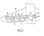
- an aircraft wing 10 has a plurality of lift control surfaces 11 mounted thereon.
- the surfaces 11 are movable between operative and inoperative positions by a motor 12 in the aircraft fuselage, the motor 12 acting through a shaft 13 and actuators 14, each of which incorporates epicyclic reduction gearing having a ratio of 500:1.
- An actuator of the general type of the actuator 14 is shown in U.S. Patent 3008355.
- a braking arrangement 15 is provided at the outboard end of the shaft 13. It will be understood that a corresponding wing on the other side of the aircraft incorporates an arrangement which is identical with that described above.
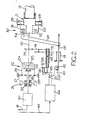
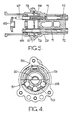
- the braking arrangement 15 is shown in more detail in Figures 2 to 5. These figures should be read in conjunction and corresponding parts therein have been assigned identical reference numerals.
- the arrangement 15 has an input shaft 20 with an internally splined portion 21 which engages a complementary spline on the shaft 13.
- a friction clutch 22 comprises three clutch plates 23 in slidable driving engagement with the shaft 20 and two clutch plates 24 between the plates 23 and in slidable driving engagement with a carrier 25.
- a spring 26 biases the plates 23, 24 into frictional engagement.
- Mounted on the carrier 25 is a plurality of planet pinions 27 each of which has 17 teeth and meshes with a 53 toothed ring gear 28 secured to a housing 29 of the arrangement 15.
- the pinions 27 also mesh with a 19 toothed sun gear 30 which is journalled around the input shaft 20 and which is in splined engagement with a flywheel 31 which is supported in bearings 32 in the housing 29.
- the flywheel 31 is of a metal having a density of 5.65 x 10 - 3 k g/ m 3 and is dimensioned so as to have a polar moment of inertia of 54 x 10- 6 kg/m 2 .
- the ratio of the gear train 27, 28, 30 is 3.79:1, and the moment of inertia of this train is approximately 44 x 10- 6 k g m 2 , whereby the total moment of inertia applied by the flywheel 31 to the shaft 13 by way of the gear train 27, 28, 30 is 8.2 x 10- 4 kgm2.
- the total moment of inertia of the remaining parts of the arrangement 15 is .47 x 10- 4 kg m 2 , whereby the effective moment of inertia of the flywheel 31 is more than seventeen times that of the remainder of the arrangement 15.
- the total moment of inertia applied by the arrangement 15 to the shaft 13 is 8.67 x 10⁻⁴ kg m2.
- the shaft 20 is drivingly connected to a transducer 40 which provides an electrical signal on a line 41 to a control unit 42 ( Figure 1) in the motor 12.
- the signal on line 41 corresponds to the angular position of the shaft 13 and is compared in the control unit 41 with a corresponding signal on a line 43 from the other wing of the aircraft.
- the control unit 42 provides signals on lines 44, 45 to effect braking of the shafts as hereinafter described.
- a further friction clutch 50 Adjacent the portion 21 of the input shaft 20 is a further friction clutch 50 which includes three plates 51 drivingly and slidably mounted on the shaft 20 and two plates 52 interposed between the plates 51, the plates 52 being drivingly and slidably mounted on a carrier 53.
- a lever 49 includes a cam face 54 such that rotation of the lever 49 anti-clockwise, as viewed in the drawings, urges the plates 51, 52 into frictional interengagement.
- the carrier 53 locates a plurality of rollers 55 between the input shaft 20 and the housing 29.
- the carrier 53 is biased by a spring 56 ( Figure 4) to a position in which the rollers 55 are aligned with recesses 57 in the housing 29, so that the rollers 55 are free to rotate.
- Engagement of the clutch 50 urges the carrier 53 away from the position shown in Figure 4 and the rollers 55 are jammed between the housing 29 and the shaft 20, to arrest movement of the latter.
- the lever 49 can be urged anti-clockwise by a plunger 60 which is biased by a spring 61 and which can be restrained against movement by the spring 61 by a roller 62 on a cranked arm 63.
- a plunger 60 which is biased by a spring 61 and which can be restrained against movement by the spring 61 by a roller 62 on a cranked arm 63.
- the lever 63 is movable by an electro-magnetic actuator 64 to release the plunger 60 and permit the lever 49 to move anti-clockwise.
- the actuator 64 is responsive to signals on the line 45.
- the lever 63 is also movable to release the plunger 60 by a further lever 65 which is biased by a spring 66 away from co-operation with the lever 63, but which can be urged against the spring 66 by threaded stems 67, 68, shown in more detail in Figure 5.
- Stems 67, 68 have respective right hand and left hand threads and engage complementary threaded sleeves 69, 70 journalled in the housing 29.
- the stems 67, 68 include portions 71 of square cross-section which pass through square holes in sleeves 72 which frictionally engage the housing 29 and prevent rotation of the stems 67, 68 the arrangement is such that rotation of the sleeve 69, 70 in one direction causes the stem 67 to be moved into engagement with the lever 65 and the stem 68 to be moved away from such engagement. Rotation of the sleeves 69, 70 in the opposite direction causes the aforesaid movement of the sleeves 67, 68 to be reversed. Moreover, with the sleeves 69, 70 stationary the stems 67, 68 may be rotated by means of the sleeves 72 for the purpose of initial setting up or testing.
- the sleeves 69, 70 include spur gears 73 which mesh with a compound gear element 74 which in turn meshes with a spur gear 75 on the shaft 20.
- the gear connection between the shaft 20 and the sleeves 69, 70 is such that the latter rotate at approximately one third of the speed of the shaft 20 and the pitch of the threads on the stems 67, 68 is such that the lever 65 is operated to trip the lever 49 and brake the shaft 20 before the control surfaces 11 ( Figure 1) reach their limiting positions in either direction of operation.
- the combined moment of inertia of each of the control surfaces 11 and actuators 14, as applied to the shaft 13, is very low, being typically .163 x 10-4 k g m2 .
- the total moment of inertia of the disconnected parts 8.82 x 1 0 -4 kg m2.
- a typical torque of 5.65 Nm applied by disconnected surface 11 to the unit 15 will result in the shaft 20 accelerating at 1020 revs/sec2.
- the shaft 20 will have rotated only 1.275 revolutions, so that the disconnected surface will have moved only about one degree from its initial position.
- the increased moment of inertia is obtained without undue increase in mass, by virtue of the step up gear in the unit 15.
- the brake in the arrangement 15 When the brake in the arrangement 15 is applied the energy in the flywheel 31 is dissipated as heat in the friction clutch 22.
Landscapes
- Engineering & Computer Science (AREA)
- Automation & Control Theory (AREA)
- Aviation & Aerospace Engineering (AREA)
- Braking Arrangements (AREA)
- Transmission Devices (AREA)
Applications Claiming Priority (2)
| Application Number | Priority Date | Filing Date | Title |
|---|---|---|---|
| GB8333848 | 1983-12-20 | ||
| GB8333848 | 1983-12-20 |
Publications (2)
| Publication Number | Publication Date |
|---|---|
| EP0146281A1 true EP0146281A1 (de) | 1985-06-26 |
| EP0146281B1 EP0146281B1 (de) | 1987-07-22 |
Family
ID=10553543
Family Applications (1)
| Application Number | Title | Priority Date | Filing Date |
|---|---|---|---|
| EP84308131A Expired EP0146281B1 (de) | 1983-12-20 | 1984-11-23 | Bremsvorrichtung für ein Drehantriebssystem |
Country Status (4)
| Country | Link |
|---|---|
| US (1) | US4633984A (de) |
| EP (1) | EP0146281B1 (de) |
| JP (1) | JPH0612134B2 (de) |
| DE (1) | DE3464875D1 (de) |
Cited By (1)
| Publication number | Priority date | Publication date | Assignee | Title |
|---|---|---|---|---|
| US12240590B2 (en) | 2021-02-25 | 2025-03-04 | Airbus Operations Gmbh | Actuator assembly for moving a movable wing tip of an aircraft |
Families Citing this family (17)
| Publication number | Priority date | Publication date | Assignee | Title |
|---|---|---|---|---|
| US4865269A (en) * | 1988-07-06 | 1989-09-12 | Sundstrand Corp. | Overtravel stop and neutral position lock |
| US4971267A (en) * | 1989-02-13 | 1990-11-20 | Allied-Signal Inc. | Multi-fuseable shaft |
| US5174419A (en) * | 1990-04-03 | 1992-12-29 | Hurth Getriebe Und Zahnraeder G.M.B.H | Spur gear transmission for a drive unit of an industrial truck with lever mounted hydraulic cylinder |
| US5310138A (en) * | 1991-12-30 | 1994-05-10 | Alliedsignal Inc. | Wing fold actuator system for aircraft |
| US5492512A (en) * | 1994-10-24 | 1996-02-20 | Chung-Da Wu | Brake system with wheel-reversing means for an automobile |
| US5743490A (en) * | 1996-02-16 | 1998-04-28 | Sundstrand Corporation | Flap/slat actuation system for an aircraft |
| US6224022B1 (en) | 1999-02-26 | 2001-05-01 | Smiths Industries Actuation Systems Inc. | Airplane high lift surface drive system |
| US6371255B1 (en) * | 1999-05-03 | 2002-04-16 | Eimco Llc | Spring applied hydraulic release brake |
| US6419606B1 (en) * | 2000-08-17 | 2002-07-16 | Eaton Corporation | Aircraft control surface drive apparatus |
| US6659398B2 (en) * | 2000-09-08 | 2003-12-09 | Smiths Aerospace, Inc. | Two-brake torque limiting device |
| US6824099B1 (en) * | 2003-07-10 | 2004-11-30 | The Boeing Company | Brake systems for aircraft wing flaps and other control surfaces |
| DE102005059369B4 (de) * | 2005-12-13 | 2012-06-14 | Airbus Operations Gmbh | Verfahren und Einrichtung zur automatischen Entlastung eines Hochauftriebsflächensystems, insbesondere eines Landeklappensystems, eines Flugzeugs |
| FR2899563B1 (fr) * | 2006-04-11 | 2009-03-20 | Airbus France Sas | Dispositif et procede d'alimentation de secours electrique a bord d'un aeronef |
| US8393442B2 (en) * | 2008-08-14 | 2013-03-12 | Hamilton Sundstrand Corporation | High gain asymmetry brake |
| DE102012020820B4 (de) | 2012-10-23 | 2022-03-17 | Liebherr-Aerospace Lindenberg Gmbh | Differenzgeschwindigkeitsabhängige Bremse |
| US10017241B2 (en) * | 2015-02-24 | 2018-07-10 | The Boeing Company | Shock absorber assembly for power drive unit of a vehicle |
| US9703312B2 (en) | 2015-09-29 | 2017-07-11 | Moog Inc. | Non-jamming stop module for high revolution applications |
Citations (4)
| Publication number | Priority date | Publication date | Assignee | Title |
|---|---|---|---|---|
| FR2372080A1 (fr) * | 1976-11-24 | 1978-06-23 | Lucas Industries Ltd | Installation de commande pour les ailerons d'une aile d'avion |
| FR2399944A1 (fr) * | 1977-08-10 | 1979-03-09 | Fuji Heavy Ind Ltd | Dispositif de securite pour organes hypersustentateurs d'avion |
| DE3102513A1 (de) * | 1980-03-27 | 1982-08-19 | Edmond 4650 Gelsenkirchen-Horst Tuttaß | Drehenergiespeicher zur bremsenergienutzung mit automatischem getriebe |
| EP0119793A1 (de) * | 1983-03-15 | 1984-09-26 | Leyland Vehicles Limited | Bremsenergiespeichergebtriebe |
Family Cites Families (4)
| Publication number | Priority date | Publication date | Assignee | Title |
|---|---|---|---|---|
| US2003552A (en) * | 1927-05-02 | 1935-06-04 | Rca Corp | Air controlled speed regulator |
| JPS5453412A (en) * | 1977-10-03 | 1979-04-26 | Akebono Brake Ind Co Ltd | Energy conservation linear motor propulsive railway vehicle |
| JPS56150648A (en) * | 1980-04-21 | 1981-11-21 | Nissan Motor Co Ltd | Recycling device of deceleration energy of car |
| JPS56169428U (de) * | 1980-05-20 | 1981-12-15 |
-
1984
- 1984-11-23 EP EP84308131A patent/EP0146281B1/de not_active Expired
- 1984-11-23 DE DE8484308131T patent/DE3464875D1/de not_active Expired
- 1984-12-03 US US06/677,222 patent/US4633984A/en not_active Expired - Lifetime
- 1984-12-12 JP JP59260957A patent/JPH0612134B2/ja not_active Expired - Lifetime
Patent Citations (4)
| Publication number | Priority date | Publication date | Assignee | Title |
|---|---|---|---|---|
| FR2372080A1 (fr) * | 1976-11-24 | 1978-06-23 | Lucas Industries Ltd | Installation de commande pour les ailerons d'une aile d'avion |
| FR2399944A1 (fr) * | 1977-08-10 | 1979-03-09 | Fuji Heavy Ind Ltd | Dispositif de securite pour organes hypersustentateurs d'avion |
| DE3102513A1 (de) * | 1980-03-27 | 1982-08-19 | Edmond 4650 Gelsenkirchen-Horst Tuttaß | Drehenergiespeicher zur bremsenergienutzung mit automatischem getriebe |
| EP0119793A1 (de) * | 1983-03-15 | 1984-09-26 | Leyland Vehicles Limited | Bremsenergiespeichergebtriebe |
Cited By (1)
| Publication number | Priority date | Publication date | Assignee | Title |
|---|---|---|---|---|
| US12240590B2 (en) | 2021-02-25 | 2025-03-04 | Airbus Operations Gmbh | Actuator assembly for moving a movable wing tip of an aircraft |
Also Published As
| Publication number | Publication date |
|---|---|
| JPH0612134B2 (ja) | 1994-02-16 |
| JPS60146928A (ja) | 1985-08-02 |
| EP0146281B1 (de) | 1987-07-22 |
| US4633984A (en) | 1987-01-06 |
| DE3464875D1 (en) | 1987-08-27 |
Similar Documents
| Publication | Publication Date | Title |
|---|---|---|
| EP0146281B1 (de) | Bremsvorrichtung für ein Drehantriebssystem | |
| US5743490A (en) | Flap/slat actuation system for an aircraft | |
| US4441675A (en) | High lift surface actuation system | |
| EP2666716B1 (de) | Integrierter Drehmomentbegrenzer / Rückstellverhinderer | |
| US5582390A (en) | Drive apparatus with primary and secondary no-back features | |
| US4493479A (en) | Hoist drive safety system | |
| EP2280194B1 (de) | Rotierendes Stellglied | |
| EP0167593A4 (de) | System zur ermittlung von fehlern an einem rotierenden verzahnten antriebsmechanismus. | |
| EP2048413A1 (de) | Aktuatoranordnung | |
| JPH0133399B2 (de) | ||
| EP0157232A1 (de) | Winde mit Schneckensicherheitseinrichtung | |
| GB1591799A (en) | Drive arrangement forlift control surfaces on all aircraft wings | |
| US6419606B1 (en) | Aircraft control surface drive apparatus | |
| EP1980770A2 (de) | Aktuatoranordnung | |
| EP3613666B1 (de) | Betätigungssystem | |
| EP0141609B1 (de) | Vorrichtung zum Begrenzen des Drehmomentes am Ausgang eines Getriebes | |
| US4890979A (en) | No-back apparatus for propeller pitch control | |
| DE102007027137B4 (de) | Bremseinheit eines Antriebssystems für Landeklappen und/oder Vorflügel zum Festlegen eines Antriebselementes | |
| US4518153A (en) | Safety mechanism for hoisting drums | |
| EP0064080B1 (de) | Sicherheitsvorrichtung für hebezeugwinden | |
| US3539041A (en) | One way brake deactivated by drive and one way clutch | |
| JPH09303521A (ja) | 主副無逆転特性を有する駆動装置、無逆転装置及び飛行機 | |
| GB2190165A (en) | Shaft relative speed limiting system | |
| CA1261436A (en) | Preventing inadvertent downthrottling of the operative engine in a multi-engine aircraft | |
| US3044558A (en) | Propeller pitch control system |
Legal Events
| Date | Code | Title | Description |
|---|---|---|---|
| PUAI | Public reference made under article 153(3) epc to a published international application that has entered the european phase |
Free format text: ORIGINAL CODE: 0009012 |
|
| AK | Designated contracting states |
Designated state(s): DE FR GB IT |
|
| 17P | Request for examination filed |
Effective date: 19851202 |
|
| 17Q | First examination report despatched |
Effective date: 19861001 |
|
| ITF | It: translation for a ep patent filed | ||
| GRAA | (expected) grant |
Free format text: ORIGINAL CODE: 0009210 |
|
| AK | Designated contracting states |
Kind code of ref document: B1 Designated state(s): DE FR GB IT |
|
| ET | Fr: translation filed | ||
| REF | Corresponds to: |
Ref document number: 3464875 Country of ref document: DE Date of ref document: 19870827 |
|
| PLBE | No opposition filed within time limit |
Free format text: ORIGINAL CODE: 0009261 |
|
| STAA | Information on the status of an ep patent application or granted ep patent |
Free format text: STATUS: NO OPPOSITION FILED WITHIN TIME LIMIT |
|
| 26N | No opposition filed | ||
| ITTA | It: last paid annual fee | ||
| PGFP | Annual fee paid to national office [announced via postgrant information from national office to epo] |
Ref country code: FR Payment date: 20011113 Year of fee payment: 18 |
|
| PGFP | Annual fee paid to national office [announced via postgrant information from national office to epo] |
Ref country code: GB Payment date: 20011121 Year of fee payment: 18 |
|
| PGFP | Annual fee paid to national office [announced via postgrant information from national office to epo] |
Ref country code: DE Payment date: 20011210 Year of fee payment: 18 |
|
| REG | Reference to a national code |
Ref country code: GB Ref legal event code: IF02 |
|
| PG25 | Lapsed in a contracting state [announced via postgrant information from national office to epo] |
Ref country code: GB Free format text: LAPSE BECAUSE OF NON-PAYMENT OF DUE FEES Effective date: 20021123 |
|
| PG25 | Lapsed in a contracting state [announced via postgrant information from national office to epo] |
Ref country code: DE Free format text: LAPSE BECAUSE OF NON-PAYMENT OF DUE FEES Effective date: 20030603 |
|
| GBPC | Gb: european patent ceased through non-payment of renewal fee | ||
| PG25 | Lapsed in a contracting state [announced via postgrant information from national office to epo] |
Ref country code: FR Free format text: LAPSE BECAUSE OF NON-PAYMENT OF DUE FEES Effective date: 20030731 |
|
| REG | Reference to a national code |
Ref country code: FR Ref legal event code: ST |
|
| REG | Reference to a national code |
Ref country code: GB Ref legal event code: 732E |