EP0146376B1 - Eléments structuraux supportant des panneaux - Google Patents
Eléments structuraux supportant des panneaux Download PDFInfo
- Publication number
- EP0146376B1 EP0146376B1 EP84308779A EP84308779A EP0146376B1 EP 0146376 B1 EP0146376 B1 EP 0146376B1 EP 84308779 A EP84308779 A EP 84308779A EP 84308779 A EP84308779 A EP 84308779A EP 0146376 B1 EP0146376 B1 EP 0146376B1
- Authority
- EP
- European Patent Office
- Prior art keywords
- elements
- limbs
- limb
- panels
- serrations
- Prior art date
- Legal status (The legal status is an assumption and is not a legal conclusion. Google has not performed a legal analysis and makes no representation as to the accuracy of the status listed.)
- Expired - Lifetime
Links
- 125000006850 spacer group Chemical group 0.000 claims description 6
- 239000011521 glass Substances 0.000 description 3
- 238000007789 sealing Methods 0.000 description 3
- 238000010079 rubber tapping Methods 0.000 description 2
- 229910000838 Al alloy Inorganic materials 0.000 description 1
- 238000001125 extrusion Methods 0.000 description 1
- 238000004519 manufacturing process Methods 0.000 description 1
Images
Classifications
-
- E—FIXED CONSTRUCTIONS
- E04—BUILDING
- E04B—GENERAL BUILDING CONSTRUCTIONS; WALLS, e.g. PARTITIONS; ROOFS; FLOORS; CEILINGS; INSULATION OR OTHER PROTECTION OF BUILDINGS
- E04B2/00—Walls, e.g. partitions, for buildings; Wall construction with regard to insulation; Connections specially adapted to walls
- E04B2/88—Curtain walls
- E04B2/96—Curtain walls comprising panels attached to the structure through mullions or transoms
- E04B2/967—Details of the cross-section of the mullions or transoms
-
- E—FIXED CONSTRUCTIONS
- E06—DOORS, WINDOWS, SHUTTERS, OR ROLLER BLINDS IN GENERAL; LADDERS
- E06B—FIXED OR MOVABLE CLOSURES FOR OPENINGS IN BUILDINGS, VEHICLES, FENCES OR LIKE ENCLOSURES IN GENERAL, e.g. DOORS, WINDOWS, BLINDS, GATES
- E06B3/00—Window sashes, door leaves, or like elements for closing wall or like openings; Layout of fixed or moving closures, e.g. windows in wall or like openings; Features of rigidly-mounted outer frames relating to the mounting of wing frames
- E06B3/68—Window bars
-
- E—FIXED CONSTRUCTIONS
- E04—BUILDING
- E04D—ROOF COVERINGS; SKY-LIGHTS; GUTTERS; ROOF-WORKING TOOLS
- E04D3/00—Roof covering by making use of flat or curved slabs or stiff sheets
- E04D3/02—Roof covering by making use of flat or curved slabs or stiff sheets of plane slabs, slates, or sheets, or in which the cross-section is unimportant
- E04D3/06—Roof covering by making use of flat or curved slabs or stiff sheets of plane slabs, slates, or sheets, or in which the cross-section is unimportant of glass or other translucent material; Fixing means therefor
- E04D3/08—Roof covering by making use of flat or curved slabs or stiff sheets of plane slabs, slates, or sheets, or in which the cross-section is unimportant of glass or other translucent material; Fixing means therefor with metal glazing bars
- E04D2003/0818—Roof covering by making use of flat or curved slabs or stiff sheets of plane slabs, slates, or sheets, or in which the cross-section is unimportant of glass or other translucent material; Fixing means therefor with metal glazing bars the supporting section of the glazing bar consisting of several parts, e.g. compound sections
-
- E—FIXED CONSTRUCTIONS
- E04—BUILDING
- E04D—ROOF COVERINGS; SKY-LIGHTS; GUTTERS; ROOF-WORKING TOOLS
- E04D3/00—Roof covering by making use of flat or curved slabs or stiff sheets
- E04D3/02—Roof covering by making use of flat or curved slabs or stiff sheets of plane slabs, slates, or sheets, or in which the cross-section is unimportant
- E04D3/06—Roof covering by making use of flat or curved slabs or stiff sheets of plane slabs, slates, or sheets, or in which the cross-section is unimportant of glass or other translucent material; Fixing means therefor
- E04D3/08—Roof covering by making use of flat or curved slabs or stiff sheets of plane slabs, slates, or sheets, or in which the cross-section is unimportant of glass or other translucent material; Fixing means therefor with metal glazing bars
- E04D2003/0843—Clamping of the sheets or glass panes to the glazing bars by means of covering strips
- E04D2003/085—Clamping of the sheets or glass panes to the glazing bars by means of covering strips locked by snap action
Definitions
- This invention relates to structural members for supporting panels, e.g. panes of glass, and has an important application in relation to what are known as patent glazing bars.
- US-A-2976969 discloses a structural member comprising two elongate elements which are drawn together by screws to grip between the elements the adjacent edges of two panels.
- FR-A-2455158 discloses a structural member comprising two elongate elements which fit together so as to be capable of gripping between them an edge portion of each of two panels between which the member is disposed, each of which elements comprises, viewed in section at right angles to its length, a channel-section portion having a base and two side walls which side walls extend towards the side walls of the other element for abutment with the faces of the respective panels to grip the panels between them, each of said elements further comprising between said side walls, two parallel limbs projecting towards the other element, and means whereby the two elements can be moved stepwise towards each other to grip the panels between them.
- the two limbs of each element project into overlapping contact with the respective limbs on the other element, one limb of each element being longer than the other limb and being formed at substantially its free end with a laterally projecting spacer flange.
- the limbs being capable of a degree of resilient flexing laterally of themselves and the mutually contacting surfaces of the limbs being formed with serrations extending lengthwise of the elements, the serrated surfaces of the two limbs of each element facing in the same direction and the serrations on the longer limb of each element facing away from the shorter limb of the same element, said spacer flange of one element extending to a position adjacent the underrated face of the longer limb of the other element, the serrations operating in conjunction with lateral flexing of the limbs to enable the two elements to be pressed together to grip the edge portions of the panels, the serrations on each limb riding over those on the co-operating limb of the other element, but to hold the elements together when the pressure is removed.
- the two elements are preferably identical in cross-section.
- screw means is provided for pulling the elements into gripping engagement with the panels.
- the screw means may conveniently extend through an aperture in the base of one of the elements and into threaded engagement with the said spacer flange of the other of the elements.
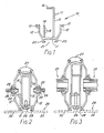
- the elongate element 10 shown in section is of extruded form and is made for example from aluminium alloy.
- the element comprises a channel-section portion with a base wall 11 and two side walls 12 and the tips of which are bifurcated to form dovetail grooves 13 for receiving sealing strips.
- two limbs 14, 15 project from the base wall, one of which is much longer than the other.
- the shorter limb 14 extends in this instance to about the same height as the side walls 11 of the channel, and the longer limb 15 has at its free end a lateral flange 16 overhanging the base 11 of the channel.
- the longer limb has on its face further from the shorter limb a band of serrations 17 which extend lengthwise of the element and the shorter limb has a similar band of serrations 18 on its face nearer the longer limb.
- Two L-section flanges 20 project from the underside of the base to form with the base a groove 21 having undercut side walls.
- two such elongate elements 10 are fitted together as shown in Figures 2 and 3 and form a patent glazing bar.
- Sealing strips 22 are located in the dovetail grooves 13 and one of the elements is inverted and its flange 16 is disposed in the gap between the limbs 14, 15 of the other element.
- the two elements are then pressed together to cause the serrations 17, 18 on the limbs to ride over each other until the sealing strips 22 grip the side margins of two panes of glass 24 ( Figure 2) or double glazing panels 25 ( Figure 3) which are separated by the member.
- the limbs flex to allow the serrations to ride over each other but when the pressure is released the serrations serve to prevent the elements from separating again.
- Self-tapping screws 26 may be provided extending with a clearance through a hole in the base 11 of the channel of the inner element into tapping engagement in a hole in the flange 16 of the outer element to apply the final pressure and/or to locate the two elements against relative slipping movement lengthwise of each other.
- limbs 14, 15 may be of any required length to enable the panels to be gripped between the side walls of the channels.
- the flanges 16 are of a length to ensure that the co-operating serrations of the shorter limb 14 of one element 10 and the longer limb 15 of the other element 10 can be engaged and disengaged by making the serrations ride over each other, causing resilient lateral flexing of the limbs, and cannot become disengaged by relative lateral movement of the elements.
- the undercut groove 21 on the outer element may accommodate a capping strip 27, while that on the inner element may conveniently accommodate flanged portions of a series of brackets 29 having laterally extending arms 30 which are formed with screw holes enabling the structural member to be secured to a succession of spaced supporting cross-members 31. So arranged, the glazing bars cannot be separated from the outer side of the assembly and the glass therefore cannot be removed from the outside. This improves the security of the arrangement. The use of identical extrusions assists in reducing production costs.
Landscapes
- Engineering & Computer Science (AREA)
- Architecture (AREA)
- Civil Engineering (AREA)
- Structural Engineering (AREA)
- Physics & Mathematics (AREA)
- Electromagnetism (AREA)
- Securing Of Glass Panes Or The Like (AREA)
Claims (4)
Applications Claiming Priority (2)
| Application Number | Priority Date | Filing Date | Title |
|---|---|---|---|
| GB8333637 | 1983-12-16 | ||
| GB838333637A GB8333637D0 (en) | 1983-12-16 | 1983-12-16 | Structural members for supporting panels |
Publications (3)
| Publication Number | Publication Date |
|---|---|
| EP0146376A2 EP0146376A2 (fr) | 1985-06-26 |
| EP0146376A3 EP0146376A3 (en) | 1987-03-04 |
| EP0146376B1 true EP0146376B1 (fr) | 1990-01-31 |
Family
ID=10553432
Family Applications (1)
| Application Number | Title | Priority Date | Filing Date |
|---|---|---|---|
| EP84308779A Expired - Lifetime EP0146376B1 (fr) | 1983-12-16 | 1984-12-14 | Eléments structuraux supportant des panneaux |
Country Status (2)
| Country | Link |
|---|---|
| EP (1) | EP0146376B1 (fr) |
| GB (1) | GB8333637D0 (fr) |
Families Citing this family (6)
| Publication number | Priority date | Publication date | Assignee | Title |
|---|---|---|---|---|
| GB8621372D0 (en) * | 1986-09-04 | 1986-10-15 | Norveaux Security Products Ltd | Window frame construction |
| EP1283311A3 (fr) | 2001-08-01 | 2004-02-11 | Aspect Management Ltd | Structures de véranda |
| GB2378208B (en) * | 2001-08-01 | 2005-05-11 | Aspect Man Ltd | Roof structures |
| GB0425643D0 (en) * | 2004-11-22 | 2004-12-22 | Chelton Brian | Extrusion |
| DE102007053013B4 (de) * | 2007-11-05 | 2012-11-29 | Klez-Systeme E.K. | Dachkonstruktion |
| IL193077A0 (en) * | 2008-07-27 | 2009-08-03 | Dan Pal | Double pane panel unit and method of assembling same |
Citations (1)
| Publication number | Priority date | Publication date | Assignee | Title |
|---|---|---|---|---|
| FR2455158A1 (fr) * | 1979-04-24 | 1980-11-21 | Dursapt Henri | Profil " petit bois " |
Family Cites Families (3)
| Publication number | Priority date | Publication date | Assignee | Title |
|---|---|---|---|---|
| US2976969A (en) * | 1958-05-05 | 1961-03-28 | Engineering Metal Products Cor | Curtain wall mullion |
| US3736717A (en) * | 1971-06-21 | 1973-06-05 | W Farley | Window and panel frame structure |
| CA1164620A (fr) * | 1981-10-07 | 1984-04-03 | Francois X. Laroche | Charpentes modulaires |
-
1983
- 1983-12-16 GB GB838333637A patent/GB8333637D0/en active Pending
-
1984
- 1984-12-14 EP EP84308779A patent/EP0146376B1/fr not_active Expired - Lifetime
Patent Citations (1)
| Publication number | Priority date | Publication date | Assignee | Title |
|---|---|---|---|---|
| FR2455158A1 (fr) * | 1979-04-24 | 1980-11-21 | Dursapt Henri | Profil " petit bois " |
Also Published As
| Publication number | Publication date |
|---|---|
| EP0146376A2 (fr) | 1985-06-26 |
| GB8333637D0 (en) | 1984-01-25 |
| EP0146376A3 (en) | 1987-03-04 |
Similar Documents
| Publication | Publication Date | Title |
|---|---|---|
| ES2037550T3 (es) | Perfil para hojas de puertas. | |
| US3028938A (en) | Locked joint and reinforcing construction for fragile sheet material | |
| US4026084A (en) | Connection members for constructional system | |
| US4907388A (en) | Modular panel frame assembly system | |
| EP0023412A1 (fr) | Entretoise pour double vitrage pourvue de moyens d'accouplement et assemblage d'angle pour ces entretoises | |
| EP0146376B1 (fr) | Eléments structuraux supportant des panneaux | |
| GB1471666A (en) | Method and fastener for use in joining together an assembly of metal sheets | |
| FR2301648A1 (fr) | Cloison et panneau utilise dans celle-ci | |
| CA2083787C (fr) | Organes d'assemblage pour ossature de plafond suspendu | |
| US3566565A (en) | Adjustable window frame | |
| US2175653A (en) | Glass-supporting metallic frame | |
| AU1107495A (en) | Shuttering panel with edge struts made from a flat extruded section | |
| US3838387A (en) | Wiring connector | |
| IE56144B1 (en) | Case for encasement of elongate objects | |
| DE3202482A1 (de) | Mehrteiliges, waermegedaemmtes metallprofil, insbesondere fuer fassaden o.dgl. | |
| US4705155A (en) | Balustrade of a passenger conveyor | |
| US5138811A (en) | Window | |
| EP0051351B1 (fr) | Assemblage de plaques | |
| JP7373381B2 (ja) | 天井ルーバーの取付構造および取付方法 | |
| GB1600358A (en) | Frame members for example for curtain walling | |
| GB2085995A (en) | Panel Joints | |
| EP1141616B1 (fr) | Elements de cadre | |
| EP1223350B1 (fr) | Agraffe pour des éléments en forme de plaque | |
| GB2178470A (en) | Glazing arrangement | |
| US4733615A (en) | Carrier rail for overhead conveyors |
Legal Events
| Date | Code | Title | Description |
|---|---|---|---|
| PUAI | Public reference made under article 153(3) epc to a published international application that has entered the european phase |
Free format text: ORIGINAL CODE: 0009012 |
|
| AK | Designated contracting states |
Designated state(s): BE FR GB |
|
| PUAL | Search report despatched |
Free format text: ORIGINAL CODE: 0009013 |
|
| AK | Designated contracting states |
Kind code of ref document: A3 Designated state(s): BE FR GB |
|
| 17P | Request for examination filed |
Effective date: 19870606 |
|
| 17Q | First examination report despatched |
Effective date: 19880811 |
|
| GRAA | (expected) grant |
Free format text: ORIGINAL CODE: 0009210 |
|
| AK | Designated contracting states |
Kind code of ref document: B1 Designated state(s): BE FR GB |
|
| ET | Fr: translation filed | ||
| PLBE | No opposition filed within time limit |
Free format text: ORIGINAL CODE: 0009261 |
|
| STAA | Information on the status of an ep patent application or granted ep patent |
Free format text: STATUS: NO OPPOSITION FILED WITHIN TIME LIMIT |
|
| 26N | No opposition filed | ||
| PGFP | Annual fee paid to national office [announced via postgrant information from national office to epo] |
Ref country code: FR Payment date: 19931109 Year of fee payment: 10 |
|
| PGFP | Annual fee paid to national office [announced via postgrant information from national office to epo] |
Ref country code: BE Payment date: 19931124 Year of fee payment: 10 |
|
| PG25 | Lapsed in a contracting state [announced via postgrant information from national office to epo] |
Ref country code: BE Effective date: 19941231 |
|
| BERE | Be: lapsed |
Owner name: BRITISH ALCAN ALUMINIUM LTD Effective date: 19941231 |
|
| PG25 | Lapsed in a contracting state [announced via postgrant information from national office to epo] |
Ref country code: FR Effective date: 19950831 |
|
| REG | Reference to a national code |
Ref country code: FR Ref legal event code: ST |
|
| REG | Reference to a national code |
Ref country code: GB Ref legal event code: 732E |
|
| PGFP | Annual fee paid to national office [announced via postgrant information from national office to epo] |
Ref country code: GB Payment date: 19991118 Year of fee payment: 16 |
|
| PG25 | Lapsed in a contracting state [announced via postgrant information from national office to epo] |
Ref country code: GB Free format text: LAPSE BECAUSE OF NON-PAYMENT OF DUE FEES Effective date: 20001214 |
|
| GBPC | Gb: european patent ceased through non-payment of renewal fee |
Effective date: 20001214 |