EP0146382B1 - Capteur de couple du type sans contact - Google Patents
Capteur de couple du type sans contact Download PDFInfo
- Publication number
- EP0146382B1 EP0146382B1 EP84308792A EP84308792A EP0146382B1 EP 0146382 B1 EP0146382 B1 EP 0146382B1 EP 84308792 A EP84308792 A EP 84308792A EP 84308792 A EP84308792 A EP 84308792A EP 0146382 B1 EP0146382 B1 EP 0146382B1
- Authority
- EP
- European Patent Office
- Prior art keywords
- magnetic
- shaft
- torque sensor
- detecting
- core member
- Prior art date
- Legal status (The legal status is an assumption and is not a legal conclusion. Google has not performed a legal analysis and makes no representation as to the accuracy of the status listed.)
- Expired - Lifetime
Links
Images




Classifications
-
- G—PHYSICS
- G01—MEASURING; TESTING
- G01L—MEASURING FORCE, STRESS, TORQUE, WORK, MECHANICAL POWER, MECHANICAL EFFICIENCY, OR FLUID PRESSURE
- G01L3/00—Measuring torque, work, mechanical power, or mechanical efficiency, in general
- G01L3/02—Rotary-transmission dynamometers
- G01L3/04—Rotary-transmission dynamometers wherein the torque-transmitting element comprises a torsionally-flexible shaft
- G01L3/10—Rotary-transmission dynamometers wherein the torque-transmitting element comprises a torsionally-flexible shaft involving electric or magnetic means for indicating
- G01L3/101—Rotary-transmission dynamometers wherein the torque-transmitting element comprises a torsionally-flexible shaft involving electric or magnetic means for indicating involving magnetic or electromagnetic means
- G01L3/102—Rotary-transmission dynamometers wherein the torque-transmitting element comprises a torsionally-flexible shaft involving electric or magnetic means for indicating involving magnetic or electromagnetic means involving magnetostrictive means
-
- G—PHYSICS
- G01—MEASURING; TESTING
- G01L—MEASURING FORCE, STRESS, TORQUE, WORK, MECHANICAL POWER, MECHANICAL EFFICIENCY, OR FLUID PRESSURE
- G01L3/00—Measuring torque, work, mechanical power, or mechanical efficiency, in general
- G01L3/02—Rotary-transmission dynamometers
- G01L3/04—Rotary-transmission dynamometers wherein the torque-transmitting element comprises a torsionally-flexible shaft
- G01L3/10—Rotary-transmission dynamometers wherein the torque-transmitting element comprises a torsionally-flexible shaft involving electric or magnetic means for indicating
- G01L3/101—Rotary-transmission dynamometers wherein the torque-transmitting element comprises a torsionally-flexible shaft involving electric or magnetic means for indicating involving magnetic or electromagnetic means
-
- G—PHYSICS
- G01—MEASURING; TESTING
- G01L—MEASURING FORCE, STRESS, TORQUE, WORK, MECHANICAL POWER, MECHANICAL EFFICIENCY, OR FLUID PRESSURE
- G01L3/00—Measuring torque, work, mechanical power, or mechanical efficiency, in general
- G01L3/02—Rotary-transmission dynamometers
- G01L3/04—Rotary-transmission dynamometers wherein the torque-transmitting element comprises a torsionally-flexible shaft
- G01L3/10—Rotary-transmission dynamometers wherein the torque-transmitting element comprises a torsionally-flexible shaft involving electric or magnetic means for indicating
- G01L3/101—Rotary-transmission dynamometers wherein the torque-transmitting element comprises a torsionally-flexible shaft involving electric or magnetic means for indicating involving magnetic or electromagnetic means
- G01L3/104—Rotary-transmission dynamometers wherein the torque-transmitting element comprises a torsionally-flexible shaft involving electric or magnetic means for indicating involving magnetic or electromagnetic means involving permanent magnets
-
- G—PHYSICS
- G01—MEASURING; TESTING
- G01L—MEASURING FORCE, STRESS, TORQUE, WORK, MECHANICAL POWER, MECHANICAL EFFICIENCY, OR FLUID PRESSURE
- G01L3/00—Measuring torque, work, mechanical power, or mechanical efficiency, in general
- G01L3/02—Rotary-transmission dynamometers
- G01L3/04—Rotary-transmission dynamometers wherein the torque-transmitting element comprises a torsionally-flexible shaft
- G01L3/10—Rotary-transmission dynamometers wherein the torque-transmitting element comprises a torsionally-flexible shaft involving electric or magnetic means for indicating
- G01L3/101—Rotary-transmission dynamometers wherein the torque-transmitting element comprises a torsionally-flexible shaft involving electric or magnetic means for indicating involving magnetic or electromagnetic means
- G01L3/105—Rotary-transmission dynamometers wherein the torque-transmitting element comprises a torsionally-flexible shaft involving electric or magnetic means for indicating involving magnetic or electromagnetic means involving inductive means
Definitions
- This invention relates to a torque sensor of noncontact type.
- the coil assembly generates a magnetic flux parallel to the axis of the shaft, and the permeability of the amorphous magnetic ribbon that is changed, according to the torque coupled to the shaft, is measured.
- this torque sensor can solve the problem noted above, since the coil assembly generates a magnetic flux parallel to the axis of the shaft, which has a relatively high magnetic reluctance, a comparatively large exciting current has to be supplied to the coil assembly.
- the coil assembly is provided around the shaft, space for providing the coil assembly is necessary around the shaft. Therefore, the torque sensor cannot be readily assembled in the system which generates the torque, and depending on systems, the space for assembling the torque sensor cannot be ensured.
- the amorphous magnetic ribbon arranged along the entire circumference of the shaft has to be given an induced magnetic anisotropy in a predetermined direction.
- the magnetic permeability of the amorphous magnetic ribbon arranged along the entire circumference of a shaft may not be uniform when the shaft is made of a Fe system. Variations of the magnetic permeability are liable tc result without variations of the torque while the entire circumference of the shaft is under measurement due to lack of uniformity of the magnetic property of the shaft. Therefore, noise is introduced into the torque detection output, and the signal-to-noise ratio is reduced.
- An object of the invention is to provide a torque sensor of a noncontact type, which can be readily disposed in a comparatively small space and can measure the torque of a shaft with a comparatively small exciting current and also with a sufficient signal-to-noise ratio.
- a torque sensor of noncontact type for sensing a torque applied to a shaft having a circumferential length Ls, comprising: a first magnetic ribbon provided on the peripheral surface of said shaft and made of a magnetic material and coil means for producing and detecting magnetic flux characterised by the first magnetic ribbon being provided on a circumferential portion of the peripheral surface having a circumferential dimension LO equal to or smaller than one half of the circumferential length Ls of said shaft and being preliminarily given an induced magnetic anisotropy in a direction at an angle with respect to the circumferential direction; a first core member made of a magnetic material and having end faces, which face said first magnetic ribbon, with a gap between the faces, the center-to-center distance L1 between said end faces of said first core member being with respect to the circumferential dimension LO of said first magnetic ribbon; said coil means comprising a first exciting coil wound on said first core member for producing a magnetic flux; and a first detecting coil wound on said first core member for detecting
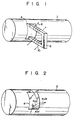
- a magnetic sheet preferably an amorphous magnetic ribbon 4 is arranged along the circumferential direction of a shaft 2 and is bonded to the shaft 2 to which rotary torque is applied. Further, an induced magnetic anisotropy is applied in advance to the amorphous magnetic ribbon 4 in the direction of angle to the circumferential direction of the ribbon.
- a U-shaped magnetic core 6 formed of a magnetic material, for example, an oxide magnetic material is disposed in the vicinity of the shaft 2, and the end faces of the core 6 are opposite to the amorphous magnetic ribbon 4 through gaps.
- An exciting coil 8 for generating a magnetic flux and a detecting coil 10 for detecting the magnetic flux depending upon the magnetic permeability of the amorphous magnetic ribbon 4 are wound around the U-shaped magnetic core 6.
- Such a torque sensor of a noncontact type detects the torque according to the principle which will be described.
- an induced magnetic anisotropy Ku is applied in advance to the amorphous magnetic ribbon 4 in the direction of angle 6>45° along the circumferential direction of the shaft 2, and its saturated magnetostriction is to be X,>0.
- a distortion stress generated at the shaft 2 is transmitted to the amorphous magnetic ribbon 4.
- a tension +a is produced in a direction of +45° to be circumferential direction in the magnetic ribbon 4
- a compression stress - ⁇ is produced in a direction of -45° to the circumferential direction.
- a magnetic anisotropy K U2 is induced by the magnetostriction in the magnetic ribbon 2 in response to these tensions + ⁇ and the compression stress -o. Therefore, a magnetic anisotropy Ku 3 is produced as the resultant vector of the magnetic anisotropies K U1 and Ku 2 .
- the magnetic permeability depends upon the direction of the vector of the magnetic anisotropy Ku 3 , and the variations in the magnetic permeability are present as variations in the mutual inductance in the magnetic ribbon 2 between the exciting coil 8 and the detecting coil 10 in the sensor as shown in Fig. 1.
- the amorphous magnetic ribbon 4 is not arranged along the entire circumference of the shaft 2 but is arranged along a given circumferential area, as shown in Figs. 1 and 2.
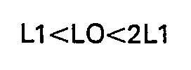
- the length LO of the amorphous magnetic ribbon 4 is suitably in a range where L1 is the effective length of the magnetic path of the magnetic core 6.
- the length L1 of the effective magnetic path of the core 6 is defined as the length of the magnetic path, which changes in the magnetic flux of the armophous magnetic ribbon 4 can be effectively detected.
- the inequality noted above is based on the following considerations.
- the core 6 can detect changes in the magnetic flux of the amorphous magnetic ribbon 4 only when the center-to-center distance between the end faces of the core 6 corresponds to the effective magnetic path length and the amorphous magnetic ribbon 4 is positioned between the centers of end faces of the core 6 while the shaft 2 is being rotated. Therefore, if the length LO of the amorphous magnetic ribbon 4 is smaller than the effective magnetic path length L1 of the minimum sensor core 6, the inductance P as shown in the graph of Fig. 4 is greatly reduced to reduce the sensitivity of detection.
- the length LO of the amorphous magnetic ribbon 4 is more than double the effective magnetic path length L1 of the core 6, i.e., 2L1 ⁇ LO, the width W of the peak shown in Fig. 4 is increased and the inductance P is varied to reduce the signal-to-noise ratio. For this reason, it is desired that there holds a condition Further, considering the fact that the core 6 has a pair of legs, the length LO is required to be less than one half the length Ls of the circumference of the shaft 2, that is, LO ⁇ 1/2 Ls.
- Fig. 5 shows a detailed structure.
- a pair of amorphous magnetic ribbons 4-1 and 4-2 are bonded by adhesive to a shaft 5 of a ferromagnetic material having a diameter of 55 mm.
- Induced magnetic anisotropy is applied to these magnetic strips 4-1 and 4-2 in directions at angles ⁇ and -8 with respect to the circumferential direction of the shaft 2.
- End faces of a pair of U-shaped magnetic cores 6-1 and 6-2 are concentrically arranged around the shaft 2 which transmits a torque with a gap of 1 mm provided between each end face of the cores and the outer surface of the magnetic strips 4-1 and 4-2.
- Exciting coils 8-1 and 8-2 and detecting coils 10-1 and 10-2 are wound on the cores 6-1 and 6-2.
- the detecting coils 10-1 and 10-2 are differentially connected as shown in Fig. 6.
- the effective magnetic path length L10 of the cores 10-1 and 10-2 is set to 10 mm. Magnetic flux is transmitted through magnetic ribbons 4-1 and 4-2 in the circumferential direction of the shaft 2.
- one peak of inductance P per rotation is produced or a plurality of peaks per rotation are produced in the case where a plurality of magnetic strips are arranged along the circumference, as shown in Fig. 4.
- the rotational rate of the torque transmission shaft can be obtained by supplying this output signal to a counter or the like.
- the output is unstable due to a reduced signal-to-noise ratio. From the above grounds, the distance LO is desirably in a range of
- a circuit for processing detection signals from the detecting coils 10-1 and 10-2 shown in Fig. 5, will be described with reference to Fig. 9.
- Exciting coils 8-1 and 8-2 which are cumulatively coupled are connected to an oscillator 12, and the differentially connected detecting coils 10-1 and 10-2 are connected to a detecting circuit 16.
- the torque coupled to the shaft 2 is changed while an AC voltage is applied to the exciting coils 8-1 and 8-2, the magnetic permeability of the amorphous magnetic ribbons 4-1 and 4-2 is changed.
- a sinusoidal detection voltage signal at a level corresponding to the magnetic permeability is detected by the detecting coils 10-1 and 10-2. That is, the detecting coils 10-1 and 10-2 generate a sinusoidal detection voltage signal corresponding to the torque coupled to the shaft 2.
- the sinusoidal voltage signal is detected by a detector 16.
- the detection signal from the detector is fed to an integrator 18 connected thereto for conversion to an integral output signal.
- the integral output signal thus obtained is converted by an analog-to-digital converter 20 connected to the integrator 18 from analog signal into digital signals.
- the digital signals thus obtained are sampled by a sample/ hold circuit 22 connected to the analog-to-digital converter 20 in a particular instant
- the shaft 2 to which torque is applied is provided with a rotation sensor 24 for detecting the rotation rate of the shaft 2.
- the rotation sensor 24 generates a rotation signal for every rotation of the shaft 2.
- a gate pulse generator 26 is connected to the rotation sensor 24, and it generates a gate pulse having a predetermined pulse width every time it receives a rotation signal.
- the gate pulse generator 26 is connected to the sample/ hold circuit 22, and the digital signal is sampled and held by the sample/hold circuit 22 in response to the gate pulse.
- the sampled and held digital voltage output is provided from an output terminal.
- the rotational rate may be detected at any point.
- the rotation signal is generated to generate a gate pulse while the amorphous magnetic ribbons 4-1 and 4-2 are temporally disposed between the centers of end faces of the cores 6-1 and 6-2.
- the amorphous magnetic ribbons 4-1 and 4-2 are arranged along only the circumference portion of the shaft 2. Accordingly, in the above circuit, magnetic characteristics of a particular circumferential portion of the amorphous magnetic ribbons 4-1 and 4-2 are sampled and held as digital signal in the sample/hold circuit 22 for each rotation of the shaft 2 to detect a torque applied to the shaft 2.
- a pulse signal is generated in synchronism to the rotational rate of the shaft 2, to which the torque is applied, and in response to this pulse, a magnetic characteristic change of the particular circumferential portion of the amorphous magnetic ribbons 4-1 and 4-2 are sampled.
- the magnetic characteristic change of the particular portion of the amorphous magnetic ribbons 4-1 and 4-2 thus can be detected in an equivalently stationary state.
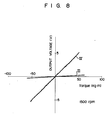
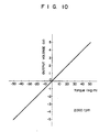
- the shaft 2 is made of a ferromagnetic material, e.g., a Fe system, it is possible to prevent output fluctuations stemming from the lack of uniformity of the magnetic permeability and obtain stable torque detection with a large signal-to-noise ratio. Further, the torque sensor itself may have a reduced size and be accommodated in a small space.
- a ferromagnetic material e.g., a Fe system
- FIG. 11 A modification of the circuit for processing the detection signal from the detecting coils employed in the torque sensor according to the invention, will now be described with reference to Fig. 11.
- reference numerals like those in Fig. 9 designate such parts.
- an averaging circuit 28 is used instead of the sample/hold circuit.
- the averaging circuit 28 includes two a arithmetic processing units, to which a pulse generator 32 is connected.
- the first arithmetic processing unit When a gate pulse is fed to the averaging circuit 28, the first arithmetic processing unit is held enable and the second arithmetic processing unit is held disenable and when the next pulse is fed to the averaging circuit 28, the first arithmetic processing unit is held disenabled and the second arithmetic processing unit is held enabled.
- the digital detection signals are fed from the A/D converter 20 to the averaging circuit and are accumulated and processed by the enabled arithmetic processing unit of the averaging circuit.
- the averaging circuit 28 provides an averaging voltage signal to output terminal 30.
- magnetic characteristics of a the amorphous magnetic ribbons 4-1 and 4-2 secured to the shaft 2 to which torque is applied are averaged by the averaging circuit 28 for each rotation of the shaft 2, whereby an average voltage digital signal corresponding to the magnetic characteristics of the amorphous magnetic ribbons 4-1 and 4-2 is provided from the output terminal 30. That is, a pulse signal is generated in synchronism of the rotational rate of the shaft 2 to which torque is applied, and the magnetic characteristics of the particular circumferential portion of the amorphous magnetic ribbons 4-1 and 4-2 are averaged in response to the pulse.
- the torque can be measured accurately by averaging and without being affected by the lack of uniformity of the magnetic permeability.
- the shaft 2 to which torque is applied is made of a ferromagnetic material, e.g., a Fe system
- the torque sensor itself may have a reduced size and be accommodated in a small space.
- the magnetic ribbon provided on a circumferential portion of the peripheral surface of the shaft and the detecting circuit having the averaging circuit, it is possible to easily detect a change of torque in a predetermined rotation angle range of the shaft.
- the amorphous magnetic ribbon 4 and core 6 may be made of Permalloy, sendust, and Fe-Si alloys as well as amorphous magnetic alloy materials. As has been shown, the circuits of Figs. 9 and 11 may be employed not only where the amorphous magnetic ribbons 4-1 and 4-2 are arranged over a part of the circumference of the shaft 2, but also where they are arranged over its entire circumference.
Landscapes
- Physics & Mathematics (AREA)
- Electromagnetism (AREA)
- General Physics & Mathematics (AREA)
- Force Measurement Appropriate To Specific Purposes (AREA)
Claims (14)

Applications Claiming Priority (6)
| Application Number | Priority Date | Filing Date | Title |
|---|---|---|---|
| JP58238658A JPS60129634A (ja) | 1983-12-17 | 1983-12-17 | トルクセンサ |
| JP238658/83 | 1983-12-17 | ||
| JP4790784A JPS60192233A (ja) | 1984-03-13 | 1984-03-13 | トルクセンサ |
| JP47907/84 | 1984-03-13 | ||
| JP5280984A JPS60196635A (ja) | 1984-03-19 | 1984-03-19 | トルクセンサ |
| JP52809/84 | 1984-03-19 |
Publications (3)
| Publication Number | Publication Date |
|---|---|
| EP0146382A2 EP0146382A2 (fr) | 1985-06-26 |
| EP0146382A3 EP0146382A3 (en) | 1986-08-27 |
| EP0146382B1 true EP0146382B1 (fr) | 1990-03-07 |
Family
ID=27293124
Family Applications (1)
| Application Number | Title | Priority Date | Filing Date |
|---|---|---|---|
| EP84308792A Expired - Lifetime EP0146382B1 (fr) | 1983-12-17 | 1984-12-17 | Capteur de couple du type sans contact |
Country Status (3)
| Country | Link |
|---|---|
| US (1) | US4590807A (fr) |
| EP (1) | EP0146382B1 (fr) |
| DE (1) | DE3481546D1 (fr) |
Families Citing this family (11)
| Publication number | Priority date | Publication date | Assignee | Title |
|---|---|---|---|---|
| JPS6275328A (ja) * | 1985-09-30 | 1987-04-07 | Toshiba Corp | トルクセンサ |
| US4762008A (en) * | 1986-05-13 | 1988-08-09 | Kabushiki Kaisha Toshiba | Torque detecting apparatus |
| JPS63210735A (ja) * | 1987-02-27 | 1988-09-01 | Honda Motor Co Ltd | 力学量検出素子 |
| JPH01189971A (ja) * | 1988-01-26 | 1989-07-31 | Toshiba Corp | トルクセンサ |
| US5144846A (en) * | 1988-07-21 | 1992-09-08 | Sensortech, L.P. | Minimal structure magnetostrictive stress and torque sensor |
| JP2783118B2 (ja) * | 1992-11-06 | 1998-08-06 | 三菱電機株式会社 | トルク検出装置 |
| US6494102B2 (en) | 2001-01-12 | 2002-12-17 | Trw Inc. | Magnetostrictive stress sensor |
| GB0129510D0 (en) * | 2001-12-10 | 2002-01-30 | Fast Technology Ag | Magnetic torque transducer |
| US20080134802A1 (en) * | 2006-12-06 | 2008-06-12 | Turbo Trac Systems Ulc | Torque sensor |
| EP2602595B1 (fr) * | 2011-12-08 | 2016-03-02 | PolyResearch AG | Capteur de force mécanique actif |
| USD887881S1 (en) * | 2018-09-10 | 2020-06-23 | China Pneumatic Corporation | Wireless torque transducer |
Family Cites Families (4)
| Publication number | Priority date | Publication date | Assignee | Title |
|---|---|---|---|---|
| SU473912A1 (ru) * | 1973-04-06 | 1975-06-14 | Пензенский Политехнический Институт | Магнитоупругий датчик |
| GB2022268B (en) * | 1978-06-02 | 1983-01-19 | Shibaura Eng Works Ltd | Stress measuring apparatus |
| DE2939566A1 (de) * | 1979-09-29 | 1981-04-09 | Zahnradfabrik Friedrichshafen Ag, 7990 Friedrichshafen | Magnetostriktives messverfahren, insbesondere zur drehmomentmessung an wellen |
| US4414855A (en) * | 1981-06-01 | 1983-11-15 | Aisin Seiki Kabushiki Kaisha | Torque sensor |
-
1984
- 1984-12-17 DE DE8484308792T patent/DE3481546D1/de not_active Expired - Lifetime
- 1984-12-17 EP EP84308792A patent/EP0146382B1/fr not_active Expired - Lifetime
- 1984-12-17 US US06/682,269 patent/US4590807A/en not_active Expired - Lifetime
Also Published As
| Publication number | Publication date |
|---|---|
| EP0146382A3 (en) | 1986-08-27 |
| DE3481546D1 (de) | 1990-04-12 |
| EP0146382A2 (fr) | 1985-06-26 |
| US4590807A (en) | 1986-05-27 |
Similar Documents
| Publication | Publication Date | Title |
|---|---|---|
| EP0217640B1 (fr) | Capteur d'un moment de torsion du type sans contact | |
| US5465627A (en) | Circularly magnetized non-contact torque sensor and method for measuring torque using same | |
| EP0523025B1 (fr) | Procédé pour mesurer un couple et/ou des contraintes axiales | |
| US5022275A (en) | Strain measuring device employing magnetostriction and having a magnetic shielding layer | |
| US7131339B2 (en) | Measurement of torsional dynamics of rotating shafts using magnetostrictive sensors | |
| CA1316714C (fr) | Appareil servant a detecter un couple | |
| US4986137A (en) | Strain detector with magnetostrictive elements | |
| US4590807A (en) | Torque sensor of noncontact type | |
| US5323659A (en) | Multifunctional torque sensor | |
| JPH0326339B2 (fr) | ||
| US4616424A (en) | Magnetic direction sensor | |
| CA1222396A (fr) | Dispositif pour mesurer le couple developpe par un arbre sans faire contact avec ledit arbre | |
| US5062307A (en) | Strain detector | |
| JPH07119657B2 (ja) | トルク検出装置 | |
| JPH0522858B2 (fr) | ||
| JPH0522859B2 (fr) | ||
| JPH04329327A (ja) | トルクセンサ | |
| JPH03269330A (ja) | トルクセンサ | |
| JPS6050429A (ja) | トルクセンサ | |
| JP2560781B2 (ja) | 歪検出装置 | |
| JPS61245032A (ja) | トルク検出装置 | |
| JPH09166504A (ja) | 磁歪式歪センサ | |
| JPH0663876B2 (ja) | 磁歪式トルクセンサの製造方法 | |
| JPH0431571Y2 (fr) | ||
| JPH01292226A (ja) | トルク検出装置 |
Legal Events
| Date | Code | Title | Description |
|---|---|---|---|
| PUAI | Public reference made under article 153(3) epc to a published international application that has entered the european phase |
Free format text: ORIGINAL CODE: 0009012 |
|
| 17P | Request for examination filed |
Effective date: 19850102 |
|
| AK | Designated contracting states |
Designated state(s): DE FR GB IT |
|
| PUAL | Search report despatched |
Free format text: ORIGINAL CODE: 0009013 |
|
| AK | Designated contracting states |
Kind code of ref document: A3 Designated state(s): DE FR GB IT |
|
| 17Q | First examination report despatched |
Effective date: 19871030 |
|
| GRAA | (expected) grant |
Free format text: ORIGINAL CODE: 0009210 |
|
| AK | Designated contracting states |
Kind code of ref document: B1 Designated state(s): DE FR GB IT |
|
| PG25 | Lapsed in a contracting state [announced via postgrant information from national office to epo] |
Ref country code: IT Free format text: LAPSE BECAUSE OF FAILURE TO SUBMIT A TRANSLATION OF THE DESCRIPTION OR TO PAY THE FEE WITHIN THE PRESCRIBED TIME-LIMIT;WARNING: LAPSES OF ITALIAN PATENTS WITH EFFECTIVE DATE BEFORE 2007 MAY HAVE OCCURRED AT ANY TIME BEFORE 2007. THE CORRECT EFFECTIVE DATE MAY BE DIFFERENT FROM THE ONE RECORDED. Effective date: 19900307 Ref country code: FR Effective date: 19900307 |
|
| REF | Corresponds to: |
Ref document number: 3481546 Country of ref document: DE Date of ref document: 19900412 |
|
| EN | Fr: translation not filed | ||
| PLBE | No opposition filed within time limit |
Free format text: ORIGINAL CODE: 0009261 |
|
| STAA | Information on the status of an ep patent application or granted ep patent |
Free format text: STATUS: NO OPPOSITION FILED WITHIN TIME LIMIT |
|
| 26N | No opposition filed | ||
| REG | Reference to a national code |
Ref country code: GB Ref legal event code: 746 Effective date: 19980929 |
|
| PGFP | Annual fee paid to national office [announced via postgrant information from national office to epo] |
Ref country code: GB Payment date: 19991215 Year of fee payment: 16 |
|
| PGFP | Annual fee paid to national office [announced via postgrant information from national office to epo] |
Ref country code: DE Payment date: 19991220 Year of fee payment: 16 |
|
| PG25 | Lapsed in a contracting state [announced via postgrant information from national office to epo] |
Ref country code: GB Free format text: LAPSE BECAUSE OF NON-PAYMENT OF DUE FEES Effective date: 20001217 |
|
| GBPC | Gb: european patent ceased through non-payment of renewal fee |
Effective date: 20001217 |
|
| PG25 | Lapsed in a contracting state [announced via postgrant information from national office to epo] |
Ref country code: DE Free format text: LAPSE BECAUSE OF NON-PAYMENT OF DUE FEES Effective date: 20011002 |