EP0146423A1 - Vorrichtung zum Messen eines seismischen Profils in einem Bohrloch - Google Patents
Vorrichtung zum Messen eines seismischen Profils in einem Bohrloch Download PDFInfo
- Publication number
- EP0146423A1 EP0146423A1 EP84402157A EP84402157A EP0146423A1 EP 0146423 A1 EP0146423 A1 EP 0146423A1 EP 84402157 A EP84402157 A EP 84402157A EP 84402157 A EP84402157 A EP 84402157A EP 0146423 A1 EP0146423 A1 EP 0146423A1
- Authority
- EP
- European Patent Office
- Prior art keywords
- geophone
- wellbore
- tool
- elasticity
- tool body
- Prior art date
- Legal status (The legal status is an assumption and is not a legal conclusion. Google has not performed a legal analysis and makes no representation as to the accuracy of the status listed.)
- Granted
Links
- 238000001514 detection method Methods 0.000 claims abstract description 4
- 230000001902 propagating effect Effects 0.000 claims description 5
- 238000001228 spectrum Methods 0.000 claims description 5
- 230000005540 biological transmission Effects 0.000 claims description 4
- 229920001971 elastomer Polymers 0.000 claims description 4
- 239000000806 elastomer Substances 0.000 claims description 4
- 230000004044 response Effects 0.000 claims description 2
- 238000005553 drilling Methods 0.000 claims 1
- 238000005259 measurement Methods 0.000 abstract description 22
- 230000006835 compression Effects 0.000 description 7
- 238000007906 compression Methods 0.000 description 7
- 230000003071 parasitic effect Effects 0.000 description 5
- 230000008878 coupling Effects 0.000 description 4
- 238000010168 coupling process Methods 0.000 description 4
- 238000005859 coupling reaction Methods 0.000 description 4
- 239000012530 fluid Substances 0.000 description 3
- 238000000034 method Methods 0.000 description 3
- 239000011435 rock Substances 0.000 description 3
- 229910000831 Steel Inorganic materials 0.000 description 1
- 230000003321 amplification Effects 0.000 description 1
- 239000004020 conductor Substances 0.000 description 1
- 238000010276 construction Methods 0.000 description 1
- 238000005474 detonation Methods 0.000 description 1
- 239000013013 elastic material Substances 0.000 description 1
- 239000002360 explosive Substances 0.000 description 1
- 230000006872 improvement Effects 0.000 description 1
- 238000003199 nucleic acid amplification method Methods 0.000 description 1
- 239000002245 particle Substances 0.000 description 1
- 229920001084 poly(chloroprene) Polymers 0.000 description 1
- 230000008569 process Effects 0.000 description 1
- 230000035939 shock Effects 0.000 description 1
- 239000002689 soil Substances 0.000 description 1
- 239000010959 steel Substances 0.000 description 1
Images
Classifications
-
- E—FIXED CONSTRUCTIONS
- E21—EARTH OR ROCK DRILLING; MINING
- E21B—EARTH OR ROCK DRILLING; OBTAINING OIL, GAS, WATER, SOLUBLE OR MELTABLE MATERIALS OR A SLURRY OF MINERALS FROM WELLS
- E21B47/00—Survey of boreholes or wells
- E21B47/01—Devices for supporting measuring instruments on drill bits, pipes, rods or wirelines; Protecting measuring instruments in boreholes against heat, shock, pressure or the like
-
- E—FIXED CONSTRUCTIONS
- E21—EARTH OR ROCK DRILLING; MINING
- E21B—EARTH OR ROCK DRILLING; OBTAINING OIL, GAS, WATER, SOLUBLE OR MELTABLE MATERIALS OR A SLURRY OF MINERALS FROM WELLS
- E21B23/00—Apparatus for displacing, setting, locking, releasing or removing tools, packers or the like in boreholes or wells
- E21B23/01—Apparatus for displacing, setting, locking, releasing or removing tools, packers or the like in boreholes or wells for anchoring the tools or the like
-
- G—PHYSICS
- G01—MEASURING; TESTING
- G01V—GEOPHYSICS; GRAVITATIONAL MEASUREMENTS; DETECTING MASSES OR OBJECTS; TAGS
- G01V1/00—Seismology; Seismic or acoustic prospecting or detecting
- G01V1/16—Receiving elements for seismic signals; Arrangements or adaptations of receiving elements
-
- G—PHYSICS
- G01—MEASURING; TESTING
- G01V—GEOPHYSICS; GRAVITATIONAL MEASUREMENTS; DETECTING MASSES OR OBJECTS; TAGS
- G01V11/00—Prospecting or detecting by methods combining techniques covered by two or more of main groups G01V1/00 - G01V9/00
- G01V11/002—Details, e.g. power supply systems for logging instruments, transmitting or recording data, specially adapted for well logging, also if the prospecting method is irrelevant
- G01V11/005—Devices for positioning logging sondes with respect to the borehole wall
-
- Y—GENERAL TAGGING OF NEW TECHNOLOGICAL DEVELOPMENTS; GENERAL TAGGING OF CROSS-SECTIONAL TECHNOLOGIES SPANNING OVER SEVERAL SECTIONS OF THE IPC; TECHNICAL SUBJECTS COVERED BY FORMER USPC CROSS-REFERENCE ART COLLECTIONS [XRACs] AND DIGESTS
- Y10—TECHNICAL SUBJECTS COVERED BY FORMER USPC
- Y10S—TECHNICAL SUBJECTS COVERED BY FORMER USPC CROSS-REFERENCE ART COLLECTIONS [XRACs] AND DIGESTS
- Y10S181/00—Acoustics
- Y10S181/40—Wave coupling
- Y10S181/401—Earth
-
- Y—GENERAL TAGGING OF NEW TECHNOLOGICAL DEVELOPMENTS; GENERAL TAGGING OF CROSS-SECTIONAL TECHNOLOGIES SPANNING OVER SEVERAL SECTIONS OF THE IPC; TECHNICAL SUBJECTS COVERED BY FORMER USPC CROSS-REFERENCE ART COLLECTIONS [XRACs] AND DIGESTS
- Y10—TECHNICAL SUBJECTS COVERED BY FORMER USPC
- Y10S—TECHNICAL SUBJECTS COVERED BY FORMER USPC CROSS-REFERENCE ART COLLECTIONS [XRACs] AND DIGESTS
- Y10S367/00—Communications, electrical: acoustic wave systems and devices
- Y10S367/911—Particular well-logging apparatus
Definitions
- the present invention relates to a measuring device for vertical seismic profile in a wellbore.
- Measurements made in a borehole generally fall into two main types.
- the first type of measurement is called ultrasonic. Such a measurement is carried out by means of a tool which is lowered into the wellbore, at the end of a cable.
- the tool comprises one or more transmitters and one or more receivers, in addition to the means necessary for triggering the transmitters at the appropriate times, and means for transmitting, on the surface of the ground, the signals received by the receivers, with a view to their recording and processing.
- Ultrasonic measurement uses transmitters capable of emitting high frequency acoustic signals, from a few thousand hertz to tens of thousands of hertz, in the fluid filling the well. Acoustic signals propagate in the fluid in the form of compression waves, the associated physical quantities of which are essentially the pressure and the speed of particles.
- the receivers used are hydrophones which are in reality sensors sensitive to vibratory pressure.
- the waves received by the sensors receive the compression waves defined above and, if need be, the parasitic waves originating from the compression waves and generated by the heterogeneities.
- the duration of each useful signal received on the sensor, after each transmission, is of the order of a few milliseconds, taking into account the frequency of the signals transmitted.
- the second type of measurement concerns a vertical seismic profile, an oblique seismic profile or another seismic well profile, this second type of measurement being completely different from the first type recalled previously for the record.
- seismic energy For oil exploration, for example, it is necessary to determine the nature and characteristics of the underground layers surrounding the wellbore. For this, we generate, on the ground surface and not in the wellbore, seismic energy by means of a detonation (explosive charge), an appropriate shock (drop in weight) or a vibrator in contact with the soil surface. This seismic energy creates waves which propagate in the underground layers and which are received on geophones and no longer on sensors.
- Geophones are, by construction, "velocimeters" sensitive to the vibrational speed, and arranged either on the surface of the ground and then they receive the waves reflected and / or refracted by the different underground layers, or in the wellbore but then they must imperatively be in direct contact with the wall of the wellbore, unlike ultrasonic measurement where the sensors must be in the fluid filling said wellbore.
- geophones or velocimeters are sensitive to the vibrational speed and must allow the determination of all types of seismic waves generated by the energy emitted at the surface.
- the direct mechanical coupling between the emission means and the ground surface gives rise to all types of waves since the seismic energy emitted necessarily encounters heterogeneities in the explored subsoil. Consequently, it is no longer possible to be satisfied with receiving on the geophone (s) a particular wave among the others, nor to accommodate a scalar quantity.
- it is necessary that the geophones receive all the waves, of compression or transverse, and in all the directions where they propagate, so as to be able, with the treatment, to distinguish all the possible directions of the vibratory velocities.
- frequencies between a few hertz and a few hundred hertz are emitted, from 5 to 500 Hz for example, the duration of the useful signal being a few seconds.
- the further processing of the signals received on the geophones makes it possible to obtain useful information on the underground layers crossed by the waves from the ground surface to the geophones.
- the device of the prior art includes a tool comprising a cylindrical element which serves to maintain the assembly of a geophone at the desired height in the wellbore, and which prevents the entire geophone from rotating relative to the tool by means of a key connection .
- the set of geophones comprises two arc spring blades, arranged symmetrically on either side of the tool which is centered in the wellbore, and connected to each other by pivots mounted on an element intermediate connected to the tool body.
- One of the spring blades is supported on the wall of the wellbore while the other carries, substantially at the top of its arrow, a shoe, pivotally mounted in the middle of the spring, said shoe being in contact by the external face on the wall opposite to that on which the first spring bears.
- a geophone is then fixed on the internal face of the shoe and it is connected by a conductive cable to the amplification equipment located inside the body of the tool.
- Such a tool constitutes a significant improvement over the technique of geophones arranged on the ground surface or distributed along the wall of the wellbore. However, it does not entirely solve the problem of direct coupling to the wall of the wellbore.
- Another disadvantage is that for a given measurement, the geophone is oriented in one direction and can therefore only detect one type of wave.
- the present invention which relates to the second type of measurement, makes it possible to provide a satisfactory solution to the problem posed and to remedy the drawbacks mentioned above.
- the subject of the present invention is a measuring device for seismic profile in a wellbore, of the type comprising emission means. arranged on the surface of the ground and capable of delivering emission signals whose frequency is included in the spectrum going from 5 and 500 Hz, a body of tool arranged in the wellbore and connected to the emission means by a cable conductor, at least one geophone mounted on elastic members which are connected to said tool body, said geophone detecting acoustic waves generated by said emission signals after propagation in underground layers which have their own elasticity at the level of the geophone, means for recording and processing the electrical signals delivered by said geophone in response to the acoustic waves received, the connection between said geophone and the recording and processing means which are arranged on the surface of the ground being carried out through said cable, and which is characterized in that the elastic members are constituted by flexible means in at least two directions and interposed between the geophone and means of application connected to the tool body and intended to apply said geophone against the wall of the wellbore during each detection of said waves, in that the
- connection of the geophone with the body of the tool by flexible means in two directions makes it possible to decouple almost completely the mass of the body of the tool from that of the geophone and, consequently, to eliminate almost all of the parasitic effects. introduced by the mass of the tool body in measures.
- the geophone is able to vibrate in the direction of the vibrational speed of the wave it receives.
- the device comprises three orthogonal geophones so as to detect both the vibrational velocities propagating in the three directions of space.
- the tool body is supported on a wall of the wellbore, opposite to that on which the geophone is applied, and comprises an articulated immobilization arm, also supported on the wall receiving the geophone.
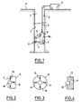
- the measuring device shown in FIG. 1 is intended to be lowered into a wellbore 1 delimited by its walls 2 and 3 and the ground surface 4.
- the wellbore 1 passes through underground layers which are not materialized on the drawings and we want to know some of their characteristics.
- a tool body 6 On the surface of the ground 4, represented schematically by a block 5, are arranged means for emitting seismic energy and means for controlling and moving a tool body 6 in the wellbore 1.
- the body 6 is suspended, in the wellbore 1, from a cable 7.
- a support arm 8 which is articulated on an axis 9 carried by the body 6.
- a geophone assembly 10 is mounted at one end of a rigid arm 11 and the other end of which is fixed to the tool body 6.
- the connection between the arm 11 and the tool body is made so that the assembly geophone 10 can be pressed against the wall 2 during a measurement of the vibratory velocities to be detected and removed from said wall 2 when the tool body 6 is moved to bring the latter into another position in the well 1.
- the geophone assembly 10, in a first embodiment is constituted by a housing 12 in which are mounted at least three springs 13 to 15 which are connected to a geophone 16 proper, so as to allow the latter to vibrate in all directions of propagation of the vibrational velocities of the waves created by the emission means 5.
- the geophone 16 is placed in the center of the box 12 and it is pushed against the wall 2 by the spring 15 while the springs 13 and 14 allow the geophone 12 to vibrate in the directions orthogonal to those of the spring 1 5 .
- the springs 13 to 15 are replaced by an elastomer block 17 disposed in the housing 12.
- the geophone 12 is then housed partly in the elastomer block 17 so as to have a free face capable of being applied against the wall 2.
- the immobilization of the tool body 6 against the walls 2 and 3 of the well 1 makes it possible to release the cable 7 and therefore also to decouple the tool body 6 relative to the positioning and emission means. 5 from the ground surface.
- the surface emission means 5 When all the measuring means are in place in the wellbore, the surface emission means 5 are excited which emit into the ground and therefore around the wellbore a signal whose frequency is between 5 and 300 Hz. This electrical signal gives rise to waves which propagate in the layers of land around the wellbore 1.
- Each type of wave created and arriving on the geophone assembly 10 is detected by the latter in the form of a speed. vibratory. The vibrations of the geophone (s) 16, in each direction are transmitted to the ground by the cable, recorded then processed by the appropriate means which will not be described in detail.
- Elastic means having such a deflection can easily be produced either from steel or from an elastic material such as neoprene.
Landscapes
- Life Sciences & Earth Sciences (AREA)
- Physics & Mathematics (AREA)
- Engineering & Computer Science (AREA)
- Geology (AREA)
- Mining & Mineral Resources (AREA)
- General Life Sciences & Earth Sciences (AREA)
- Environmental & Geological Engineering (AREA)
- Geophysics (AREA)
- Fluid Mechanics (AREA)
- Geochemistry & Mineralogy (AREA)
- General Physics & Mathematics (AREA)
- Acoustics & Sound (AREA)
- Remote Sensing (AREA)
- Geophysics And Detection Of Objects (AREA)
- Buildings Adapted To Withstand Abnormal External Influences (AREA)
Applications Claiming Priority (2)
| Application Number | Priority Date | Filing Date | Title |
|---|---|---|---|
| FR8317788 | 1983-11-09 | ||
| FR8317788A FR2554600B1 (fr) | 1983-11-09 | 1983-11-09 | Dispositif de mesure pour profil sismique dans un puits de forage |
Publications (2)
| Publication Number | Publication Date |
|---|---|
| EP0146423A1 true EP0146423A1 (de) | 1985-06-26 |
| EP0146423B1 EP0146423B1 (de) | 1988-02-03 |
Family
ID=9293922
Family Applications (1)
| Application Number | Title | Priority Date | Filing Date |
|---|---|---|---|
| EP84402157A Expired EP0146423B1 (de) | 1983-11-09 | 1984-10-26 | Vorrichtung zum Messen eines seismischen Profils in einem Bohrloch |
Country Status (12)
| Country | Link |
|---|---|
| US (1) | US4811814A (de) |
| EP (1) | EP0146423B1 (de) |
| AU (1) | AU578433B2 (de) |
| BR (1) | BR8405708A (de) |
| CA (1) | CA1216924A (de) |
| DE (1) | DE3469230D1 (de) |
| FR (1) | FR2554600B1 (de) |
| IN (1) | IN161198B (de) |
| IT (1) | IT1177153B (de) |
| MX (1) | MX156271A (de) |
| NO (1) | NO161587C (de) |
| OA (1) | OA07859A (de) |
Families Citing this family (14)
| Publication number | Priority date | Publication date | Assignee | Title |
|---|---|---|---|---|
| JPH0785109B2 (ja) * | 1985-07-24 | 1995-09-13 | シュルンベルジェ オーバーシーズ エス.エイ. | ダウンホ−ル地震探査装置 |
| DZ1241A1 (fr) * | 1987-08-13 | 2004-09-13 | Schlumberger Ltd | Procédé pour coupler un module de détection sismique à la paroi d'un sondage et sonde pour sa mise en oeuvre. |
| US5200581A (en) * | 1987-08-13 | 1993-04-06 | Schlumberger Technology Corporation | Method of coupling a seimic detector module to the wall of a borehole, and a sonde for implementing the method |
| US5044461A (en) * | 1991-01-10 | 1991-09-03 | Western Atlas International, Inc. | Decoupled borehole sensor |
| FR2692364B1 (fr) * | 1992-06-12 | 1994-07-29 | Inst Francais Du Petrole | Systeme sismique mobile de grande longueur pour puits. |
| RU2030766C1 (ru) * | 1993-01-05 | 1995-03-10 | Виктор Никифорович Лисин | Способ сейсмической разведки |
| GB2344174B (en) | 1998-07-10 | 2002-09-11 | Schlumberger Ltd | Borehole seismic tool |
| US7048089B2 (en) * | 2003-05-07 | 2006-05-23 | Battelle Energy Alliance, Llc | Methods and apparatus for use in detecting seismic waves in a borehole |
| US7874362B2 (en) * | 2007-03-26 | 2011-01-25 | Schlumberger Technology Corporation | Determination of downhole pressure while pumping |
| US9103203B2 (en) * | 2007-03-26 | 2015-08-11 | Schlumberger Technology Corporation | Wireless logging of fluid filled boreholes |
| US20080253226A1 (en) * | 2007-04-11 | 2008-10-16 | Stig Rune Lennart Tenghamn | System and method for marine seismic surveying |
| US8654606B2 (en) * | 2010-07-27 | 2014-02-18 | Westerngeco L.L.C. | Obtaining a response based on differencing of outputs of sensors |
| US9081110B2 (en) * | 2012-12-18 | 2015-07-14 | Schlumberger Technology Corporation | Devices, systems and methods for low frequency seismic borehole investigations |
| CN115373019B (zh) * | 2022-07-19 | 2023-04-07 | 中国科学院地质与地球物理研究所 | 一种高灵敏度、宽频带、全倾角地震检波器 |
Citations (6)
| Publication number | Priority date | Publication date | Assignee | Title |
|---|---|---|---|---|
| FR1169871A (fr) * | 1956-03-21 | 1959-01-07 | Exxon Research Engineering Co | Géophone |
| US3626364A (en) * | 1969-07-15 | 1971-12-07 | Little Inc A | Three-axis seismometer |
| FR2172808A1 (de) * | 1972-02-22 | 1973-10-05 | Inst Francais Du Petrole | |
| US4056004A (en) * | 1976-09-02 | 1977-11-01 | Dresser Industries, Inc. | Multiple arm pad instrument for logging highly deviated boreholes |
| US4325259A (en) * | 1980-10-07 | 1982-04-20 | Westinghouse Electric Corp. | Vibration amplitude measuring device |
| FR2530345A1 (fr) * | 1982-07-13 | 1984-01-20 | Schlumberger Prospection | Procede pour coupler un detecteur sismique a la paroi d'un forage, et sonde d'acquisition sismique pour la mise en oeuvre de ce procede |
Family Cites Families (14)
| Publication number | Priority date | Publication date | Assignee | Title |
|---|---|---|---|---|
| US31607A (en) * | 1861-03-05 | Improvement in transmitting motion | ||
| CA649113A (en) * | 1962-09-25 | B. Hildebrandt Alexander | Geophone assembly | |
| US2963641A (en) * | 1958-08-01 | 1960-12-06 | Shell Oil Co | Exploration of earth formations associated with petroleum deposits |
| US3542150A (en) * | 1968-10-10 | 1970-11-24 | Dresser Ind | Acoustic well-logging apparatus having angled acoustic transducers |
| US3475722A (en) * | 1968-11-07 | 1969-10-28 | Marathon Oil Co | Method and apparatus for acoustic bore hole logging using acoustic signals of controlled direction |
| US3648515A (en) * | 1969-10-29 | 1972-03-14 | Dresser Ind | Radioactivity logging apparatus having shielded wall contacting source and detector |
| US3978939A (en) * | 1971-05-24 | 1976-09-07 | Schlumberger Technology Corporation | Acoustic well logging methods and apparatus |
| US3794976A (en) * | 1972-05-30 | 1974-02-26 | Schlumberger Technology Corp | Methods and apparatus for acoustically investigating earth formations using shear waves |
| US3798966A (en) * | 1972-08-29 | 1974-03-26 | Schlumberger Technology Corp | Well logging sonde having articulated centering and measuring shoes |
| SU711514A1 (ru) * | 1975-12-17 | 1980-01-25 | Научно-Производственное Объединение "Геофизика" Министерства Геологии Ссср | Центрирующее устройство дл скважинного прибора акустического каротажа |
| SU586410A1 (ru) * | 1976-01-04 | 1977-12-30 | Всесоюзный Научно-Исследовательский Институт По Осуществлению Месторождений Полезных Ископоемых,Специальным Горным Работам,Рудничной Геологии И Маркшейдерскому Делу | Устройство дл приема упругих колебаний |
| USRE31607E (en) | 1977-07-28 | 1984-06-19 | Shell Oil Company | Circumferential acoustical detector |
| US4578785A (en) * | 1983-06-06 | 1986-03-25 | Western Geophysical Company Of America | Two-component acoustic borehole tool |
| FR2556478B1 (fr) * | 1983-12-09 | 1986-09-05 | Elf Aquitaine | Procede et dispositif de mesures geophysiques dans un puits fore |
-
1983
- 1983-11-09 FR FR8317788A patent/FR2554600B1/fr not_active Expired
-
1984
- 1984-10-26 EP EP84402157A patent/EP0146423B1/de not_active Expired
- 1984-10-26 DE DE8484402157T patent/DE3469230D1/de not_active Expired
- 1984-10-27 IN IN804/MAS/84A patent/IN161198B/en unknown
- 1984-10-30 CA CA000466627A patent/CA1216924A/en not_active Expired
- 1984-11-05 NO NO844387A patent/NO161587C/no unknown
- 1984-11-06 MX MX203299A patent/MX156271A/es unknown
- 1984-11-07 AU AU35171/84A patent/AU578433B2/en not_active Ceased
- 1984-11-08 BR BR8405708A patent/BR8405708A/pt not_active IP Right Cessation
- 1984-11-09 OA OA58436A patent/OA07859A/xx unknown
- 1984-11-09 IT IT23524/84A patent/IT1177153B/it active
-
1987
- 1987-01-29 US US07/009,586 patent/US4811814A/en not_active Expired - Fee Related
Patent Citations (6)
| Publication number | Priority date | Publication date | Assignee | Title |
|---|---|---|---|---|
| FR1169871A (fr) * | 1956-03-21 | 1959-01-07 | Exxon Research Engineering Co | Géophone |
| US3626364A (en) * | 1969-07-15 | 1971-12-07 | Little Inc A | Three-axis seismometer |
| FR2172808A1 (de) * | 1972-02-22 | 1973-10-05 | Inst Francais Du Petrole | |
| US4056004A (en) * | 1976-09-02 | 1977-11-01 | Dresser Industries, Inc. | Multiple arm pad instrument for logging highly deviated boreholes |
| US4325259A (en) * | 1980-10-07 | 1982-04-20 | Westinghouse Electric Corp. | Vibration amplitude measuring device |
| FR2530345A1 (fr) * | 1982-07-13 | 1984-01-20 | Schlumberger Prospection | Procede pour coupler un detecteur sismique a la paroi d'un forage, et sonde d'acquisition sismique pour la mise en oeuvre de ce procede |
Non-Patent Citations (1)
| Title |
|---|
| V.H. PITT: "The Penguin dictionary of physics", 1977, pages 120,247-248, Penguin Books, éd.: V.H. Pitt, Harmondsworth, GB; * |
Also Published As
| Publication number | Publication date |
|---|---|
| IT1177153B (it) | 1987-08-26 |
| EP0146423B1 (de) | 1988-02-03 |
| IT8423524A0 (it) | 1984-11-09 |
| OA07859A (fr) | 1986-11-20 |
| NO161587B (no) | 1989-05-22 |
| FR2554600A1 (fr) | 1985-05-10 |
| IT8423524A1 (it) | 1986-05-09 |
| US4811814A (en) | 1989-03-14 |
| NO844387L (no) | 1985-05-10 |
| AU578433B2 (en) | 1988-10-27 |
| AU3517184A (en) | 1985-05-16 |
| CA1216924A (en) | 1987-01-20 |
| IN161198B (de) | 1987-10-17 |
| DE3469230D1 (en) | 1988-03-10 |
| MX156271A (es) | 1988-08-03 |
| BR8405708A (pt) | 1985-09-10 |
| NO161587C (no) | 1989-08-30 |
| FR2554600B1 (fr) | 1986-02-07 |
Similar Documents
| Publication | Publication Date | Title |
|---|---|---|
| EP0148667B1 (de) | Verfahren und Gerät für geophysikalische Messungen in einem Bohrloch | |
| EP0156660B1 (de) | Vorrichtung für geophysikalische Messungen in einem Bohrloch | |
| EP0146423B1 (de) | Vorrichtung zum Messen eines seismischen Profils in einem Bohrloch | |
| FR2532058A1 (fr) | Appareil et procede de diagraphie acoustique et procede de reduction du bruit du aux ondes de compression et de stoneley | |
| CA1311833C (fr) | Geophone comportant un element sensible en polymere piezoelectrique | |
| FR2650336A1 (fr) | Procede et dispositif pour determiner un profil sismique vertical par la mesure de vibrations provenant d'un forage | |
| FR2754607A1 (fr) | Appareillage et procede pour l'exploration sismique d'un puits de forage | |
| JP4889900B2 (ja) | 地震波受信装置および地震波受信装置を下層土のような固体媒体に結合する方法 | |
| FR2551222A1 (fr) | Appareil et procede de diagraphie | |
| FR2700018A1 (fr) | Méthode et dispositif de prospection sismique utilisant un outil de forage en action dans un puits. | |
| EP0291388B1 (de) | Seismisches Prospektionsverfahren für die Bestimmung von unterirdischen geologischen Schichten | |
| FR2538562A1 (fr) | Methode et appareillage de detection des fractures par echographie ultrasonique le long de la paroi d'un materiau ou d'une formation | |
| FR2563273A1 (fr) | Dispositif pour transmettre des donnees d'un emetteur a un recepteur par un train de tiges de forage dans un sondage | |
| FR2609177A1 (fr) | Procede et appareil pour former acoustiquement des images de la paroi d'un trou de sonde | |
| EP0769606B1 (de) | Gerät zum Erkunden einer von einem horizontalen Bohrloch durchquerten, unterirdischen Formation mittels Sensoren | |
| EP2643747A2 (de) | System zur erkennung und ortung einer störung in einem medium sowie entsprechendes medium und computerprogramm | |
| CA2213685C (fr) | Dispositif de couplage d'un systeme de reception a la paroi d'un puits | |
| FR2969770A1 (fr) | Procede, dispositif et unite de reception pour l'acquisition sismique au fond de la mer | |
| EP0232646B1 (de) | Feststellgerät für eine Kardanmontierte Detektorgruppe | |
| FR2585127A2 (fr) | Transducteur de pression a resonateur | |
| EP0118329B1 (de) | Geschwindigkeitshydrophon | |
| EP1041403B1 (de) | Kompakter seismischer Vibrator und Verfahren zur seiner Verwendung in seismische Überwachung und Prospektion | |
| EP0296933A1 (de) | Verfahren und Gerät zur seismischen Untersuchung einer Umgebung mittels induzierter Wellen, die in einem Bohrloch künstlich erregt werden | |
| EP1546762B1 (de) | Einrichtung zur seismischen emission in einer unterirdischen formation und verfahren zu ihrer implementierung | |
| EP0458947B1 (de) | Verfahren und vorrichtung zur datenerfassung von seismischen messwerten aus bohrlöchern in zwei entgegengesetzten richtungen |
Legal Events
| Date | Code | Title | Description |
|---|---|---|---|
| PUAI | Public reference made under article 153(3) epc to a published international application that has entered the european phase |
Free format text: ORIGINAL CODE: 0009012 |
|
| AK | Designated contracting states |
Designated state(s): DE GB NL |
|
| 17P | Request for examination filed |
Effective date: 19850812 |
|
| 17Q | First examination report despatched |
Effective date: 19861121 |
|
| GRAA | (expected) grant |
Free format text: ORIGINAL CODE: 0009210 |
|
| AK | Designated contracting states |
Kind code of ref document: B1 Designated state(s): DE GB NL |
|
| GBT | Gb: translation of ep patent filed (gb section 77(6)(a)/1977) | ||
| REF | Corresponds to: |
Ref document number: 3469230 Country of ref document: DE Date of ref document: 19880310 |
|
| PLBE | No opposition filed within time limit |
Free format text: ORIGINAL CODE: 0009261 |
|
| STAA | Information on the status of an ep patent application or granted ep patent |
Free format text: STATUS: NO OPPOSITION FILED WITHIN TIME LIMIT |
|
| 26N | No opposition filed | ||
| PGFP | Annual fee paid to national office [announced via postgrant information from national office to epo] |
Ref country code: DE Payment date: 19930630 Year of fee payment: 10 |
|
| PGFP | Annual fee paid to national office [announced via postgrant information from national office to epo] |
Ref country code: GB Payment date: 19941018 Year of fee payment: 11 |
|
| PGFP | Annual fee paid to national office [announced via postgrant information from national office to epo] |
Ref country code: NL Payment date: 19941031 Year of fee payment: 11 |
|
| PG25 | Lapsed in a contracting state [announced via postgrant information from national office to epo] |
Ref country code: DE Effective date: 19950701 |
|
| PG25 | Lapsed in a contracting state [announced via postgrant information from national office to epo] |
Ref country code: GB Effective date: 19951026 |
|
| PG25 | Lapsed in a contracting state [announced via postgrant information from national office to epo] |
Ref country code: NL Effective date: 19960501 |
|
| GBPC | Gb: european patent ceased through non-payment of renewal fee |
Effective date: 19951026 |
|
| NLV4 | Nl: lapsed or anulled due to non-payment of the annual fee |
Effective date: 19960501 |