EP0146426A1 - Verfahren für die Steuerung eines Motors mit durch Lambdasonde regulierter Kraftstoffeinspritzung und gesteuerter Zündung - Google Patents
Verfahren für die Steuerung eines Motors mit durch Lambdasonde regulierter Kraftstoffeinspritzung und gesteuerter Zündung Download PDFInfo
- Publication number
- EP0146426A1 EP0146426A1 EP84402175A EP84402175A EP0146426A1 EP 0146426 A1 EP0146426 A1 EP 0146426A1 EP 84402175 A EP84402175 A EP 84402175A EP 84402175 A EP84402175 A EP 84402175A EP 0146426 A1 EP0146426 A1 EP 0146426A1
- Authority
- EP
- European Patent Office
- Prior art keywords
- engine
- temporary
- enrichment
- injection time
- nominal
- Prior art date
- Legal status (The legal status is an assumption and is not a legal conclusion. Google has not performed a legal analysis and makes no representation as to the accuracy of the status listed.)
- Granted
Links
- 238000002347 injection Methods 0.000 title claims abstract description 64
- 239000007924 injection Substances 0.000 title claims abstract description 64
- 238000000034 method Methods 0.000 title claims abstract description 30
- 239000000446 fuel Substances 0.000 title claims abstract description 18
- 239000000523 sample Substances 0.000 title claims description 20
- 230000001276 controlling effect Effects 0.000 title description 3
- 230000001105 regulatory effect Effects 0.000 title description 2
- 239000000203 mixture Substances 0.000 claims abstract description 26
- ATJFFYVFTNAWJD-UHFFFAOYSA-N Tin Chemical compound [Sn] ATJFFYVFTNAWJD-UHFFFAOYSA-N 0.000 claims abstract description 16
- 230000009467 reduction Effects 0.000 claims abstract description 14
- 229910052760 oxygen Inorganic materials 0.000 claims abstract description 9
- 239000001301 oxygen Substances 0.000 claims abstract description 9
- QVGXLLKOCUKJST-UHFFFAOYSA-N atomic oxygen Chemical compound [O] QVGXLLKOCUKJST-UHFFFAOYSA-N 0.000 claims abstract description 8
- 239000007789 gas Substances 0.000 claims abstract description 8
- 230000004044 response Effects 0.000 claims abstract description 7
- 230000001133 acceleration Effects 0.000 claims description 2
- 230000001052 transient effect Effects 0.000 claims description 2
- 239000002826 coolant Substances 0.000 claims 1
- 238000012360 testing method Methods 0.000 description 46
- 230000006870 function Effects 0.000 description 10
- 230000008569 process Effects 0.000 description 8
- 238000013507 mapping Methods 0.000 description 4
- 238000010586 diagram Methods 0.000 description 3
- 230000008901 benefit Effects 0.000 description 2
- 239000000498 cooling water Substances 0.000 description 2
- 230000000737 periodic effect Effects 0.000 description 2
- XLYOFNOQVPJJNP-UHFFFAOYSA-N water Substances O XLYOFNOQVPJJNP-UHFFFAOYSA-N 0.000 description 2
- 239000004215 Carbon black (E152) Substances 0.000 description 1
- UGFAIRIUMAVXCW-UHFFFAOYSA-N Carbon monoxide Chemical compound [O+]#[C-] UGFAIRIUMAVXCW-UHFFFAOYSA-N 0.000 description 1
- 230000032683 aging Effects 0.000 description 1
- 230000002238 attenuated effect Effects 0.000 description 1
- 230000003416 augmentation Effects 0.000 description 1
- 229910002091 carbon monoxide Inorganic materials 0.000 description 1
- 230000003247 decreasing effect Effects 0.000 description 1
- 230000006735 deficit Effects 0.000 description 1
- 238000001514 detection method Methods 0.000 description 1
- 230000000694 effects Effects 0.000 description 1
- 238000005562 fading Methods 0.000 description 1
- 229930195733 hydrocarbon Natural products 0.000 description 1
- 150000002430 hydrocarbons Chemical class 0.000 description 1
- 238000012986 modification Methods 0.000 description 1
- 230000004048 modification Effects 0.000 description 1
- 150000002926 oxygen Chemical class 0.000 description 1
- 230000010363 phase shift Effects 0.000 description 1
- 231100000331 toxic Toxicity 0.000 description 1
- 230000002588 toxic effect Effects 0.000 description 1
- 238000012546 transfer Methods 0.000 description 1
- 230000017105 transposition Effects 0.000 description 1
Images

Classifications
-
- F—MECHANICAL ENGINEERING; LIGHTING; HEATING; WEAPONS; BLASTING
- F02—COMBUSTION ENGINES; HOT-GAS OR COMBUSTION-PRODUCT ENGINE PLANTS
- F02D—CONTROLLING COMBUSTION ENGINES
- F02D41/00—Electrical control of supply of combustible mixture or its constituents
- F02D41/02—Circuit arrangements for generating control signals
- F02D41/04—Introducing corrections for particular operating conditions
- F02D41/10—Introducing corrections for particular operating conditions for acceleration
-
- F—MECHANICAL ENGINEERING; LIGHTING; HEATING; WEAPONS; BLASTING
- F02—COMBUSTION ENGINES; HOT-GAS OR COMBUSTION-PRODUCT ENGINE PLANTS
- F02D—CONTROLLING COMBUSTION ENGINES
- F02D37/00—Non-electrical conjoint control of two or more functions of engines, not otherwise provided for
- F02D37/02—Non-electrical conjoint control of two or more functions of engines, not otherwise provided for one of the functions being ignition
-
- F—MECHANICAL ENGINEERING; LIGHTING; HEATING; WEAPONS; BLASTING
- F02—COMBUSTION ENGINES; HOT-GAS OR COMBUSTION-PRODUCT ENGINE PLANTS
- F02D—CONTROLLING COMBUSTION ENGINES
- F02D41/00—Electrical control of supply of combustible mixture or its constituents
- F02D41/22—Safety or indicating devices for abnormal conditions
-
- F—MECHANICAL ENGINEERING; LIGHTING; HEATING; WEAPONS; BLASTING
- F02—COMBUSTION ENGINES; HOT-GAS OR COMBUSTION-PRODUCT ENGINE PLANTS
- F02D—CONTROLLING COMBUSTION ENGINES
- F02D41/00—Electrical control of supply of combustible mixture or its constituents
- F02D41/24—Electrical control of supply of combustible mixture or its constituents characterised by the use of digital means
- F02D41/2406—Electrical control of supply of combustible mixture or its constituents characterised by the use of digital means using essentially read only memories
- F02D41/2425—Particular ways of programming the data
- F02D41/2429—Methods of calibrating or learning
- F02D41/2451—Methods of calibrating or learning characterised by what is learned or calibrated
- F02D41/2454—Learning of the air-fuel ratio control
- F02D41/2458—Learning of the air-fuel ratio control with an additional dither signal
Definitions
- the present invention relates to a method for controlling a fuel injection and spark-ignition engine by means of an electronic computer coupled to a probe for detecting the oxygen content of the exhaust gases, hereinafter called probe / ⁇ .
- the probe A is an all-or-nothing sensor whose output voltage is either higher or lower than a certain threshold depending on whether the oxygen content of the exhaust gases is lower or higher than a predetermined value.
- This oxygen content of the exhaust gases is itself an image of the mixture of air and fuel admitted into the engine: a lean mixture generates an excess of oxygen in the exhaust gases and a rich mixture a deficit of oxygen, the threshold of the probe A corresponding to the stoichiometric ratio.
- Such a probe A can thus be used in combination with an injection computer to measure the air / fuel mixture admitted into the engine as a function of the oxygen content of the exhaust gases.
- This regulation makes it possible in particular to reduce the emissions of toxic components from spark-ignition engines as required by national regulations in a certain number of countries.
- Another advantage of such regulation by probe lies in the possibility of operating the engine in a lean mixture, at least in certain areas of its operating range, in order to minimize fuel consumption and reduce carbon monoxide and unburnt hydrocarbon emissions.
- the invention aims to solve this problem and, for this purpose, it relates to a method for controlling a fuel injection engine and controlled ignition equipped with an electronic injection and ignition computer coupled to a detection probe.
- the oxygen content of the exhaust gases according to which a nominal advance advance angle is developed as a function of the engine operating parameters which is temporarily reduced in certain operating conditions of the engine and a nominal injection time corresponding to a low-fuel dosage of the fuel mixture and a temporary enrichment of said mixture is periodically caused by an increase in injection time, characterized in that, in response to said temporary enrichment , said temporary reduction in the angle of advance at nominal ignition is caused and in that the amplitude of the reduction in the angle of advance at ignition is proportional to said nominal angle of advance and depends on the value of the temporary increase in injection time.
- the temporary advance reduction is generated a predetermined number of engine revolutions after the start of the temporary enrichment.
- a positive-ignition engine 1 comprises an intake pipe 2, in which an injector 3 is arranged downstream of a throttle valve 4, and an exhaust pipe 5, The time
- a digital computer 6 which receives from a pressure sensor 7 information relating to the air pressure in the supply line intake 2 and a speed sensor 8 information relating to the speed of rotation of the engine 1.
- the sensor 8 is associated with a toothed target 9 integral in rotation with the crankshaft (not shown) of the engine 1 and some of whose teeth have been suppressed the output signal from the sensor 8 is thus used by the computer 6 to determine both the speed and the angular position of the crankshaft as described in patent FR-A- 79.00 386.
- the computer 6 also receives the signals from output of a probe A 10 arranged in the exhaust pipe 5 and of a temperature sensor 11 disposed in the cooling water circuit 12 of the engine 1.
- the computer 6 also develops the ignition advance angle as a function of the engine speed and load parameters and controls the instant of ignition of the mixture in a cylinder 13 of the engine by a spark plug 14.
- the computer 6 has in memory a map making it possible to calculate the injection time as a function of the speed and of the engine load.
- This mapping corresponds to a basic injection time TIo determining an operation of the engine in lean mixture.
- the speed and the load of the engine, and therefore the basic injection time TIo are assumed to be constant.
- the computer 6 causes an additional enrichment of the mixture by increasing the injection time by a value b during a number of engine revolutions a.
- the quantities a and b are calculated so that, at the operating point considered, the probe A is at the limit of tilting.
- the basic injection time is reduced by a small amount and, if not, it is increased by an equally small amount, which leads to a nominal injection time TIn different from the basic time TIo.
- this temporary enrichment (a, b) tends to generate an increase in torque which, in accordance with the invention, is compensated by an equally temporary reduction in the angle of advance on ignition.
- this comprises in memory an addressable advance map as a function of the pressure and the engine speed and generates a basic advance angle Avo.
- the advance angle Avo is reduced by an amount e during a number of revolutions f.
- the values of a, b, c, d, e, f and g depend on the type of injection system and on the characteristics of the engine considered.
- the duration of the advance enrichment and blurring slots (a, f) can be fixed because the injectors deliver the fuel directly on the intake valves.
- the duration of the slots enrichment and advance blurring should then preferably depend on the engine operating point, which can be achieved by memorization, of a specific mapping in the digital advance and injection computer 6.
- the amplitude b of the enrichment slot is preferably inversely proportional to the nominal richness, that is to say to the nominal injection time, for the considered operating point of the engine, while the value e of the Advance shading is preferably proportional to the amplitude b of the enrichment window.
- the phase shift g between the enrichment slot and the advance dimming slot can be either fixed, or a function of the engine load and speed. The same goes for the repetition period d of the temporary enrichment process and for the number of revolutions c at the end of which the condition of the probe is examined. If a is fixed, it is preferably also, but if a depends on the load and the engine speed, c can either depend on the same parameters, or be a predetermined number of turns counted from the end of the slot. enrichment.
- the regulation by temporary enrichment and blurring described above may only be carried out in certain engine operating zones. This type of regulation will preferably be avoided in the field of high loads (rich mixture), low loads (deceleration zones) and low speeds (stability problems). This regulation should preferably also be prohibited during transient or cold operations because of deceleration cuts and acceleration and cold enrichments that can be expected and that the regulation described would disturb.
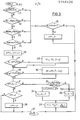
- FIG. 3 precisely illustrates an embodiment of the invention which eliminates regulation by temporary enrichment and blurring in advance in the above-mentioned operating zones.
- the values of a, c, d, f and g will be assumed to be fixed.
- the response to at least one of tests 21 to 24 is negative and we pass to test 25.
- the state of the probe ⁇ used as a looping criterion for an injection system programmed to operate in lean mixture, is used so as to periodically make the mixture generated tend to the stoichiometric report.
- This results in changes to the programmed base injection time which provide self-adaptive control of the nominal wealth for each engine operating point programmed in the computer mapping, which overcomes variations in characteristics due to engine aging.
- This regulation is made acceptable in its application on a motor vehicle by the fact that the excess torque normally generated by the periodic enrichment is considerably attenuated by the periodic blurring in advance carried out.
Landscapes
- Engineering & Computer Science (AREA)
- Chemical & Material Sciences (AREA)
- Combustion & Propulsion (AREA)
- Mechanical Engineering (AREA)
- General Engineering & Computer Science (AREA)
- Electrical Control Of Air Or Fuel Supplied To Internal-Combustion Engine (AREA)
Applications Claiming Priority (2)
| Application Number | Priority Date | Filing Date | Title |
|---|---|---|---|
| FR8317538A FR2554509B1 (fr) | 1983-11-04 | 1983-11-04 | Procede de commande d'un moteur a injection de carburant regulee par sonde l et a allumage commande |
| FR8317538 | 1983-11-04 |
Publications (2)
| Publication Number | Publication Date |
|---|---|
| EP0146426A1 true EP0146426A1 (de) | 1985-06-26 |
| EP0146426B1 EP0146426B1 (de) | 1988-05-11 |
Family
ID=9293783
Family Applications (1)
| Application Number | Title | Priority Date | Filing Date |
|---|---|---|---|
| EP84402175A Expired EP0146426B1 (de) | 1983-11-04 | 1984-10-30 | Verfahren für die Steuerung eines Motors mit durch Lambdasonde regulierter Kraftstoffeinspritzung und gesteuerter Zündung |
Country Status (3)
| Country | Link |
|---|---|
| EP (1) | EP0146426B1 (de) |
| DE (1) | DE3471131D1 (de) |
| FR (1) | FR2554509B1 (de) |
Families Citing this family (2)
| Publication number | Priority date | Publication date | Assignee | Title |
|---|---|---|---|---|
| US5127383A (en) * | 1988-12-10 | 1992-07-07 | Robert Bosch Gmbh | Adaptive acceleration enrichment for petrol injection systems |
| FR2721653A1 (fr) * | 1994-06-27 | 1995-12-29 | Siemens Automotive Sa | Procédé et dispositif de réduction des émissions de polluants d'un moteur à combustion interne. |
Citations (5)
| Publication number | Priority date | Publication date | Assignee | Title |
|---|---|---|---|---|
| EP0007998A1 (de) * | 1978-08-08 | 1980-02-20 | Robert Bosch Gmbh | Verfahren und Vorrichtung zur wenigstens teilweisen Unterbrechung der Kraftstoffzufuhr bei vorzugsweise in Fahrzeugen eingebauten Brennkraftmaschinen im Schiebebetrieb |
| DE2852715B1 (de) * | 1978-12-06 | 1980-06-19 | Volkswagenwerk Ag | Verfahren zum Betrieb einer Brennkraftmaschine und Brennkraftmaschine zur Durchfuehrung des Verfahrens |
| GB2047439A (en) * | 1979-04-06 | 1980-11-26 | Nissan Motor | Air-fuel ratio control system for internal combustion engines |
| FR2465887A1 (fr) * | 1979-08-02 | 1981-03-27 | Fuji Heavy Ind Ltd | Dispositif de commande du rapport air-combustible pour un moteur a combustion interne |
| EP0042163A2 (de) * | 1980-06-14 | 1981-12-23 | Robert Bosch Gmbh | Verfahren zur Steuerung der Kraftstoffzumessung und des Zündzeitpunkts einer Brennkraftmaschine |
Family Cites Families (2)
| Publication number | Priority date | Publication date | Assignee | Title |
|---|---|---|---|---|
| IT1081383B (it) * | 1977-04-27 | 1985-05-21 | Magneti Marelli Spa | Apparecchiatura elettronica per il controllo dell'alimentazione di una miscela aria/benzina di un motore a combustione interna |
| JPS58104342A (ja) * | 1981-12-16 | 1983-06-21 | Toyota Motor Corp | 内燃機関の空燃比制御方法 |
-
1983
- 1983-11-04 FR FR8317538A patent/FR2554509B1/fr not_active Expired
-
1984
- 1984-10-30 EP EP84402175A patent/EP0146426B1/de not_active Expired
- 1984-10-30 DE DE8484402175T patent/DE3471131D1/de not_active Expired
Patent Citations (5)
| Publication number | Priority date | Publication date | Assignee | Title |
|---|---|---|---|---|
| EP0007998A1 (de) * | 1978-08-08 | 1980-02-20 | Robert Bosch Gmbh | Verfahren und Vorrichtung zur wenigstens teilweisen Unterbrechung der Kraftstoffzufuhr bei vorzugsweise in Fahrzeugen eingebauten Brennkraftmaschinen im Schiebebetrieb |
| DE2852715B1 (de) * | 1978-12-06 | 1980-06-19 | Volkswagenwerk Ag | Verfahren zum Betrieb einer Brennkraftmaschine und Brennkraftmaschine zur Durchfuehrung des Verfahrens |
| GB2047439A (en) * | 1979-04-06 | 1980-11-26 | Nissan Motor | Air-fuel ratio control system for internal combustion engines |
| FR2465887A1 (fr) * | 1979-08-02 | 1981-03-27 | Fuji Heavy Ind Ltd | Dispositif de commande du rapport air-combustible pour un moteur a combustion interne |
| EP0042163A2 (de) * | 1980-06-14 | 1981-12-23 | Robert Bosch Gmbh | Verfahren zur Steuerung der Kraftstoffzumessung und des Zündzeitpunkts einer Brennkraftmaschine |
Non-Patent Citations (1)
| Title |
|---|
| PATENTS ABSTRACTS OF JAPAN, vol. 7, no. 207(M-242)[1352], 13 septembre 1983, page 70M242; & JP - A - 58 104 342 (TOYOTA JIDOSHA KOGYO K.K.) 21-06-1983 * |
Also Published As
| Publication number | Publication date |
|---|---|
| FR2554509A1 (fr) | 1985-05-10 |
| DE3471131D1 (en) | 1988-06-16 |
| FR2554509B1 (fr) | 1988-03-18 |
| EP0146426B1 (de) | 1988-05-11 |
Similar Documents
| Publication | Publication Date | Title |
|---|---|---|
| KR102599556B1 (ko) | 배기가스 성분을 위한 촉매 컨버터의 저장기의 충전 레벨을 조절하기 위한 방법 및 제어부 | |
| FR2466633A1 (fr) | Systeme de commande de synchronisation d'etincelles pour moteurs a combustion interne | |
| FR2803877A1 (fr) | Procede et dispositif de surveillance de fonctionnement d'un clapet pour ecoulement des gaz, notamment d'un moteur a combustion interne | |
| FR2759117A1 (fr) | Procedes et dispositifs pour la commande d'un moteur a combustion interne | |
| FR3033364A1 (fr) | Dispositif et procede de regulation de la richesse d'un moteur a combustion interne | |
| FR2780447A1 (fr) | Procede de correction de la duree d'injection dans un moteur a combustion interne a systeme d'air secondaire | |
| EP0175596B1 (de) | Verfahren für die anpassungsfähige Steuerung der Kraftstoffeinspritzung eines Einspritzmotors | |
| FR2541728A1 (fr) | Procede de reglage du ralenti par reaction dans un moteur a combustion interne | |
| FR2463287A1 (fr) | Dispositif et procede de commande du rapport air-combustible pour un carburateur de moteur a combustion interne | |
| EP0236207B1 (de) | Elektronisches Einspritzverfahren und -system mit Lambdasondenregelung für Brennkraftmaschinen | |
| EP0146426B1 (de) | Verfahren für die Steuerung eines Motors mit durch Lambdasonde regulierter Kraftstoffeinspritzung und gesteuerter Zündung | |
| EP0856099B1 (de) | System und verfahren mit einem doppelten regelungskreis für brennkraftmaschine | |
| FR2796670A1 (fr) | Procede et dispositif de commande du mode de combustion d'un moteur a combustion interne | |
| WO2022018332A1 (fr) | Procede de correction d'une derive de mesure de richesse | |
| FR2737920A1 (fr) | Procede de diagnostic pour un detecteur de gaz d'echappement | |
| EP0852667B1 (de) | Verfahren zur bestimmung des einem verbrennungsmotor zugeführten optimalen luft-kraftstoff-verhältnisses und entsprechende vorrichtung | |
| EP1760295B1 (de) | Regelvorrichtung für eine Diesel-Brennkraftmaschine mit Abgasrückführung | |
| EP0636778B1 (de) | Verfahren und Vorrichtung zum korrigieren der Kraftstoffeinspritzungsdauer in Abhängigkeit des Durchflusses einer Tankentlüftungsanlage für einen Einspritzmotor | |
| WO1998028615A1 (fr) | Procede de diagnostic electrique d'une sonde a oxygene d'un moteur a combustion interne | |
| EP1693559B1 (de) | Steuerungssystem zum Betreiben eines Dieselmotors mit Abgasrückführung | |
| EP1170494B1 (de) | Verfahren zur Regelung des einem Verbrennungsmotor zugeführten Kraftstoff-Luftgemischgehaltes | |
| FR2851788A1 (fr) | Procede de determination du gain d'un injecteur de carburant | |
| FR2892769A1 (fr) | Strategie de reconnaissance de taux de carburant exotique dans le reservoir principal | |
| JP3493697B2 (ja) | エンジンの空燃比制御装置 | |
| FR2722248A1 (fr) | Procede et dispositif de regulation de las richesse de combustion d'un moteur a combustion interne |
Legal Events
| Date | Code | Title | Description |
|---|---|---|---|
| PUAI | Public reference made under article 153(3) epc to a published international application that has entered the european phase |
Free format text: ORIGINAL CODE: 0009012 |
|
| 17P | Request for examination filed |
Effective date: 19841105 |
|
| AK | Designated contracting states |
Designated state(s): DE GB IT SE |
|
| 17Q | First examination report despatched |
Effective date: 19870109 |
|
| D17Q | First examination report despatched (deleted) | ||
| GRAA | (expected) grant |
Free format text: ORIGINAL CODE: 0009210 |
|
| AK | Designated contracting states |
Kind code of ref document: B1 Designated state(s): DE GB IT SE |
|
| ITF | It: translation for a ep patent filed | ||
| REF | Corresponds to: |
Ref document number: 3471131 Country of ref document: DE Date of ref document: 19880616 |
|
| GBT | Gb: translation of ep patent filed (gb section 77(6)(a)/1977) | ||
| PLBE | No opposition filed within time limit |
Free format text: ORIGINAL CODE: 0009261 |
|
| STAA | Information on the status of an ep patent application or granted ep patent |
Free format text: STATUS: NO OPPOSITION FILED WITHIN TIME LIMIT |
|
| 26N | No opposition filed | ||
| ITTA | It: last paid annual fee | ||
| EAL | Se: european patent in force in sweden |
Ref document number: 84402175.8 |
|
| PGFP | Annual fee paid to national office [announced via postgrant information from national office to epo] |
Ref country code: SE Payment date: 19960923 Year of fee payment: 13 |
|
| PG25 | Lapsed in a contracting state [announced via postgrant information from national office to epo] |
Ref country code: SE Free format text: LAPSE BECAUSE OF NON-PAYMENT OF DUE FEES Effective date: 19971031 |
|
| EUG | Se: european patent has lapsed |
Ref document number: 84402175.8 |
|
| PGFP | Annual fee paid to national office [announced via postgrant information from national office to epo] |
Ref country code: GB Payment date: 19990913 Year of fee payment: 16 |
|
| PGFP | Annual fee paid to national office [announced via postgrant information from national office to epo] |
Ref country code: DE Payment date: 19990927 Year of fee payment: 16 |
|
| PG25 | Lapsed in a contracting state [announced via postgrant information from national office to epo] |
Ref country code: GB Free format text: LAPSE BECAUSE OF NON-PAYMENT OF DUE FEES Effective date: 20001030 |
|
| GBPC | Gb: european patent ceased through non-payment of renewal fee |
Effective date: 20001030 |
|
| PG25 | Lapsed in a contracting state [announced via postgrant information from national office to epo] |
Ref country code: DE Free format text: LAPSE BECAUSE OF NON-PAYMENT OF DUE FEES Effective date: 20010703 |