EP0146473B1 - Klarsichtfenster für Haushaltskochgerät mit Antibeschlagmitteln - Google Patents
Klarsichtfenster für Haushaltskochgerät mit Antibeschlagmitteln Download PDFInfo
- Publication number
- EP0146473B1 EP0146473B1 EP19840402578 EP84402578A EP0146473B1 EP 0146473 B1 EP0146473 B1 EP 0146473B1 EP 19840402578 EP19840402578 EP 19840402578 EP 84402578 A EP84402578 A EP 84402578A EP 0146473 B1 EP0146473 B1 EP 0146473B1
- Authority
- EP
- European Patent Office
- Prior art keywords
- cooker
- window according
- wall
- window
- flap
- Prior art date
- Legal status (The legal status is an assumption and is not a legal conclusion. Google has not performed a legal analysis and makes no representation as to the accuracy of the status listed.)
- Expired
Links
- 238000010411 cooking Methods 0.000 title description 26
- 239000000463 material Substances 0.000 claims description 4
- 238000011144 upstream manufacturing Methods 0.000 claims description 2
- 238000007688 edging Methods 0.000 claims 1
- 238000009833 condensation Methods 0.000 description 7
- 230000005494 condensation Effects 0.000 description 7
- XLYOFNOQVPJJNP-UHFFFAOYSA-N water Substances O XLYOFNOQVPJJNP-UHFFFAOYSA-N 0.000 description 5
- 239000007789 gas Substances 0.000 description 4
- 239000003570 air Substances 0.000 description 3
- 230000008034 disappearance Effects 0.000 description 2
- 239000003517 fume Substances 0.000 description 2
- 230000005484 gravity Effects 0.000 description 2
- 238000012423 maintenance Methods 0.000 description 2
- 230000000284 resting effect Effects 0.000 description 2
- 239000000126 substance Substances 0.000 description 2
- 239000012780 transparent material Substances 0.000 description 2
- 239000012080 ambient air Substances 0.000 description 1
- 230000000903 blocking effect Effects 0.000 description 1
- 238000004140 cleaning Methods 0.000 description 1
- 230000008094 contradictory effect Effects 0.000 description 1
- 230000001934 delay Effects 0.000 description 1
- 238000001914 filtration Methods 0.000 description 1
- 239000011521 glass Substances 0.000 description 1
- 239000004519 grease Substances 0.000 description 1
- 238000009413 insulation Methods 0.000 description 1
- 239000007788 liquid Substances 0.000 description 1
- 239000003595 mist Substances 0.000 description 1
- 238000012544 monitoring process Methods 0.000 description 1
- 235000019645 odor Nutrition 0.000 description 1
- 239000002245 particle Substances 0.000 description 1
- 230000000737 periodic effect Effects 0.000 description 1
- 229920002492 poly(sulfone) Polymers 0.000 description 1
- 230000001737 promoting effect Effects 0.000 description 1
- 238000007789 sealing Methods 0.000 description 1
- 238000002604 ultrasonography Methods 0.000 description 1
Images

Classifications
-
- A—HUMAN NECESSITIES
- A47—FURNITURE; DOMESTIC ARTICLES OR APPLIANCES; COFFEE MILLS; SPICE MILLS; SUCTION CLEANERS IN GENERAL
- A47J—KITCHEN EQUIPMENT; COFFEE MILLS; SPICE MILLS; APPARATUS FOR MAKING BEVERAGES
- A47J36/00—Parts, details or accessories of cooking-vessels
- A47J36/38—Parts, details or accessories of cooking-vessels for withdrawing or condensing cooking vapors from cooking utensils
-
- A—HUMAN NECESSITIES
- A47—FURNITURE; DOMESTIC ARTICLES OR APPLIANCES; COFFEE MILLS; SPICE MILLS; SUCTION CLEANERS IN GENERAL
- A47J—KITCHEN EQUIPMENT; COFFEE MILLS; SPICE MILLS; APPARATUS FOR MAKING BEVERAGES
- A47J37/00—Baking; Roasting; Grilling; Frying
- A47J37/12—Deep fat fryers, e.g. for frying fish or chips
- A47J37/1204—Deep fat fryers, e.g. for frying fish or chips for domestic use
- A47J37/1209—Deep fat fryers, e.g. for frying fish or chips for domestic use electrically heated
Definitions
- the present invention relates to a porthole for a household cooking appliance, such as an oven, a stove, a fryer or the like, fixed or mobile, the porthole being able in particular to be incorporated into a cover, attached to such an appliance.
- a household cooking appliance such as an oven, a stove, a fryer or the like
- a known solution for devices provided with a porthole disposed in a cover mounted on their upper part, consists in placing the porthole obliquely with respect to the plane of the cover to avoid the parking of the condensation water. But only the sufficiently large drops of water flow by gravity; the fine droplets and the drops of fatty substance remain fixed on the internal face of the cover, the forces which they undergo due to the surface tension of the liquid being greater than that which results from gravity.
- Another known solution (GB-A-2 119 635) consists in making a double-walled porthole.
- the transparent wall which is on the internal side of the cooking appliance is tightly mounted in the cover and is covered by a movable flap spaced from this wall so that the latter is isolated from the outside environment by a layer of air trapped between it and the shutter.
- the internal wall is therefore brought to a temperature close to that of the cooking vapors, which eliminates the fogging resulting from the initial condensation.
- the temperature rise thereof is long, which consequently delays the disappearance of the condensation and the possibility of monitoring the advance of cooking.
- the document DE-B-1.019.451 describes an oven door comprising two openings in the wall which supports the porthole, these openings being equipped with valves and being arranged one at the top the other at the bottom of the door of the oven.
- the present invention aims to overcome the drawbacks listed above and by creating a porthole for a cooking appliance comprising particularly simple means for preventing condensation on its transparent wall.
- a device porthole comprising a transparent plate mounted in a wall of the appliance and covered with a movable flap spaced from the transparent plate to create a space between them, and a communication passage between the interior of the cooking appliance and the space between the transparent plate and the flap, characterized in that the communication passage is a bypass of an exhaust duct between the interior and the exterior of the cooking appliance.
- filtering means are arranged in the communication passage.
- the wall of a household cooking appliance here the cover 1 of a fryer equipped with a porthole according to the invention.
- the cover 1 has at its upper part a frame 2 providing a compartment 3 in communication with the interior of the fryer by slots 4 and containing a filter 5 held in place by a removable valve 6 having lights 7 (see Figures 1 and 3).
- the frame 2 also encloses a porthole comprising a transparent plate 8 mounted in an opening in the cover 1 and covered with a movable flap 9 spaced from the transparent wall to create a space 10 between them.
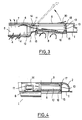
- a bypass 11 is made between the space 10 and the compartment 3 forming an exhaust duct between the interior and the exterior of the cooking appliance so that through the compartment 3 and the bypass 11 is obtains a communication passage between the interior of the cooking appliance and the space 10 between the transparent plate 8 and the flap 9 (see FIGS. 3 and 4).
- the cover 1 In its part constituting the lower wall of compartment 3, the cover 1 comprises a circular rib 12 directed towards the inside of compartment 3 and constituting a sealing rim in connection with the lower face of the filter cartridge 5. Furthermore, the valve 6 is kept slightly apart from the upper face of the cartridge 5 by means of leaf springs or bosses (not shown) fixed on the lower face of the valve 6 and resting on the upper face of the cartridge 5, so that the vapors coming from inside the fryer and having passed through the filter cartridge 5 can partly escape on the side of the filter cartridge towards the bypass 11 and the filter cartridge 5 thus constitutes filter means arranged in the passage of communication between the interior of the cooking appliance and the space 10, upstream of the bypass 11.
- the space 10 between the transparent plate 8 and the flap 9 is surrounded by a side wall 13 having openings in the form of nozzles 14 facing the exhaust duct formed by the compartment 3.
- the transparent plate comprises a flange 15 bearing on the internal face of the cover 1 and a skirt 16 extending towards the outside of the device and cooperating with the side wall 13 of the space 10 between the transparent plate 8 and the flap 9.
- the transparent plate 8 and the side wall 13 are made of materials which can be welded together, for example made of polysulfone which is weldable by ultrasound, and are thus made integral with one another during assembly.
- the flap 9 is articulated along one of its edges by means of two tenons 17 engaging in corresponding cells of the frame 2.
- the flap 9 is made of a flexible material and has on its edge opposite the articulated edge a lug blocking device 18 cooperating with the edge of an opening 19 in the frame 1.
- the flap 9 has a notch 20, the opening of which is directed towards the lug 18.
- a slight clearance 21 is provided between the edge of the flap 9 and the edge of the opening 19.
- the operation of the device is as follows: at the start of cooking, the fryer cover is closed and the shutter 9 is also closed with the lug 18 engaged under the edge of the opening 19 in the frame 2 and resting on the upper edge of the side wall 13. From the start of cooking, the hot vapors are pushed through. slots 4 by the differential pressure existing between the interior of the container and the exterior; these vapors pass through the filter cartridge 5 and escape mainly through the ports 7.
- the ports 7 however constitute a resistance to the escape of the vapors so that a part of these goes towards the bypass 11 and enters the space 10 where it comes to heat the upper surface of the transparent plate 8. while the lower face of this transparent plate 8 is heated by the steam contained inside the container.
- the plate 8 is heated simultaneously on its two faces and quickly reaches a temperature at which the water vapor formed during cooking in the container can no longer condense on the plate 8.
- the size of the openings 14 forming the bypass 11 should preferably be large enough to allow a flow of hot vapors sufficient to heat the plate 8, but also not be too large, so that these vapors, which contain water vapor, do not interfere with the observation of the user when the latter opens the flap 9.
- the hot vapors contained in the space 10 can partly escape towards the outside of the device, even when the shutter 9 is closed and the gases trapped in the space 10 are thus renewed so that this space is maintained at a high temperature, promoting the temperature maintenance of the transparent plate 8.
- the present invention is not limited to the embodiment described above and it is possible to make variant embodiments.
- the shutter 9 can be made to slide instead of being tilted as in the embodiment shown and provision can be made to remove the lug 18, the shutter 9 then being closed by its own weight.
- the flap 9 is made of a transparent material so that, under certain conditions, the user can observe the state of cooking of the food without opening the flap 9.
- the transparent plate 8 is inclined so as to promote a flow of projections resulting from cooking on the internal face of the transparent plate. This arrangement improves vision, but is not essential, the disappearance of the mist being in itself sufficient to allow good vision of the food during cooking.
- exhaust nozzles are provided in one side of the side wall adjacent or preferably opposite to that which contains the nozzles 14. These exhaust nozzles, associated with openings in the frame 2 allow a greater vapor escape than through clearance 21 and therefore promote circulation of hot steam in space 10.
Landscapes
- Engineering & Computer Science (AREA)
- Food Science & Technology (AREA)
- Cookers (AREA)
- Baking, Grill, Roasting (AREA)
- Frying-Pans Or Fryers (AREA)
Claims (10)
Applications Claiming Priority (2)
| Application Number | Priority Date | Filing Date | Title |
|---|---|---|---|
| FR8320003 | 1983-12-14 | ||
| FR8320003A FR2556576B1 (fr) | 1983-12-14 | 1983-12-14 | Hublot pour appareil menager de cuisson avec dispositif anti-buee |
Publications (3)
| Publication Number | Publication Date |
|---|---|
| EP0146473A2 EP0146473A2 (de) | 1985-06-26 |
| EP0146473A3 EP0146473A3 (en) | 1985-08-14 |
| EP0146473B1 true EP0146473B1 (de) | 1987-06-16 |
Family
ID=9295156
Family Applications (1)
| Application Number | Title | Priority Date | Filing Date |
|---|---|---|---|
| EP19840402578 Expired EP0146473B1 (de) | 1983-12-14 | 1984-12-13 | Klarsichtfenster für Haushaltskochgerät mit Antibeschlagmitteln |
Country Status (3)
| Country | Link |
|---|---|
| EP (1) | EP0146473B1 (de) |
| DE (2) | DE146473T1 (de) |
| FR (1) | FR2556576B1 (de) |
Families Citing this family (4)
| Publication number | Priority date | Publication date | Assignee | Title |
|---|---|---|---|---|
| JPS63189130U (de) * | 1987-05-28 | 1988-12-05 | ||
| FR2705878B1 (fr) * | 1993-06-03 | 1995-07-13 | Seb Sa | Couvercle pour récipient culinaire à ouverture réglable et récipient culinaire équipé d'un tel couvercle. |
| FR2712791B1 (fr) * | 1993-11-25 | 1996-01-19 | Garcia Fernand | Installation de cuisson et panier pour une telle installation. |
| FR2928821B1 (fr) * | 2008-03-20 | 2010-03-19 | Seb Sa | Couvercle d'appareil de cuisson comportant un hublot a double paroi |
Family Cites Families (4)
| Publication number | Priority date | Publication date | Assignee | Title |
|---|---|---|---|---|
| DE1019451B (de) * | 1954-05-19 | 1957-11-14 | Karel Groenhof | Einrichtung an Doppeltueren von Brat- und Backroehren, insbesondere von Herden |
| FR1273751A (fr) * | 1960-11-16 | 1961-10-13 | Tappan Co | Fourneau à gaz |
| US3509868A (en) * | 1967-06-19 | 1970-05-05 | Skagersviks Ind Ab | Arrangement in oven openings |
| FR2525888A1 (fr) * | 1982-04-30 | 1983-11-04 | Moulinex Sa | Couvercle pour cuve de cuisson |
-
1983
- 1983-12-14 FR FR8320003A patent/FR2556576B1/fr not_active Expired
-
1984
- 1984-12-13 DE DE1984402578 patent/DE146473T1/de active Pending
- 1984-12-13 DE DE8484402578T patent/DE3464201D1/de not_active Expired
- 1984-12-13 EP EP19840402578 patent/EP0146473B1/de not_active Expired
Also Published As
| Publication number | Publication date |
|---|---|
| DE146473T1 (de) | 1985-10-10 |
| DE3464201D1 (en) | 1987-07-23 |
| EP0146473A2 (de) | 1985-06-26 |
| FR2556576B1 (fr) | 1987-01-09 |
| FR2556576A1 (fr) | 1985-06-21 |
| EP0146473A3 (en) | 1985-08-14 |
Similar Documents
| Publication | Publication Date | Title |
|---|---|---|
| WO1993010698A1 (fr) | Appareil de cuisson a ventilation forcee | |
| EP0713668B1 (de) | Kochgerät von Gas-Grill Typ | |
| EP1996052A2 (de) | Abdeckung für einen küchenartikel mit silikondichtung | |
| EP0137809A1 (de) | Elektrisches fritiergerät | |
| EP0146473B1 (de) | Klarsichtfenster für Haushaltskochgerät mit Antibeschlagmitteln | |
| CA2268810A1 (fr) | Appareil de cuisson electrique comportant un dispositif de condensation des vapeurs de cuisson | |
| JP2009261892A (ja) | フライパン | |
| FR2550611A1 (fr) | Foyer pour cheminee mixte destine a fonctionner ouvert et ferme | |
| EP0663568B1 (de) | Haushaltskochofen | |
| FR2965466A1 (fr) | Appareil de cuisson electrique comportant un couvercle pivotant equipe d'un dispositif de recuperation des condensats | |
| EP2147622B1 (de) | Deckel eines Elektro-Haushaltsgeräts zum Kochen, der eine Filteruntereinheit umfasst | |
| EP0740518B1 (de) | Kochgerät, beispielsweise friteuse | |
| EP0719987B1 (de) | Verbesserter Gaskocher | |
| BE1001612A3 (fr) | Appareil de chauffage a combustible solide. | |
| EP0142452B1 (de) | Deckel für Kochherde oder für Heizeinrichtungen | |
| FR2759770A1 (fr) | Four menager avec garniture d'etancheite pour l'ouverture frontale d'alimentation | |
| LU81821A1 (fr) | Dispositif de collecte et d'evacuation des condensats dans les appareils culinaires | |
| EP0669498B1 (de) | Feuerstätte für festen oder flüssigen Brennstoff | |
| WO2024189296A1 (fr) | Appareil de cuisson polyvalent de type four, barbecue et plancha | |
| FR2705878A1 (fr) | Couvercle pour récipient culinaire à ouverture réglable et récipient culinaire équipé d'un tel couvercle. | |
| EP4570136A1 (de) | Elektrisches lebensmittelzubereitungsgerät | |
| JP3112730U (ja) | てんぷら鍋 | |
| EP1298394A1 (de) | Haushaltsofen | |
| BE896081A (fr) | Friteuse electrique | |
| FR2724832A1 (fr) | Appareil de cuisson et dispositif formant catalyseur pour un tel appareil |
Legal Events
| Date | Code | Title | Description |
|---|---|---|---|
| PUAI | Public reference made under article 153(3) epc to a published international application that has entered the european phase |
Free format text: ORIGINAL CODE: 0009012 |
|
| PUAL | Search report despatched |
Free format text: ORIGINAL CODE: 0009013 |
|
| 17P | Request for examination filed |
Effective date: 19841217 |
|
| AK | Designated contracting states |
Designated state(s): BE CH DE GB LI |
|
| AK | Designated contracting states |
Designated state(s): BE CH DE GB LI |
|
| DET | De: translation of patent claims | ||
| 17Q | First examination report despatched |
Effective date: 19860811 |
|
| GRAA | (expected) grant |
Free format text: ORIGINAL CODE: 0009210 |
|
| AK | Designated contracting states |
Kind code of ref document: B1 Designated state(s): BE CH DE GB LI |
|
| REF | Corresponds to: |
Ref document number: 3464201 Country of ref document: DE Date of ref document: 19870723 |
|
| PLBE | No opposition filed within time limit |
Free format text: ORIGINAL CODE: 0009261 |
|
| STAA | Information on the status of an ep patent application or granted ep patent |
Free format text: STATUS: NO OPPOSITION FILED WITHIN TIME LIMIT |
|
| 26N | No opposition filed | ||
| PGFP | Annual fee paid to national office [announced via postgrant information from national office to epo] |
Ref country code: CH Payment date: 19911217 Year of fee payment: 8 |
|
| PGFP | Annual fee paid to national office [announced via postgrant information from national office to epo] |
Ref country code: GB Payment date: 19921210 Year of fee payment: 9 |
|
| PG25 | Lapsed in a contracting state [announced via postgrant information from national office to epo] |
Ref country code: LI Effective date: 19921231 Ref country code: CH Effective date: 19921231 |
|
| PGFP | Annual fee paid to national office [announced via postgrant information from national office to epo] |
Ref country code: BE Payment date: 19930128 Year of fee payment: 9 |
|
| PGFP | Annual fee paid to national office [announced via postgrant information from national office to epo] |
Ref country code: DE Payment date: 19930225 Year of fee payment: 9 |
|
| REG | Reference to a national code |
Ref country code: CH Ref legal event code: PL |
|
| PG25 | Lapsed in a contracting state [announced via postgrant information from national office to epo] |
Ref country code: GB Effective date: 19931213 |
|
| PG25 | Lapsed in a contracting state [announced via postgrant information from national office to epo] |
Ref country code: BE Effective date: 19931231 |
|
| BERE | Be: lapsed |
Owner name: SEB S.A. Effective date: 19931231 |
|
| GBPC | Gb: european patent ceased through non-payment of renewal fee |
Effective date: 19931213 |
|
| PG25 | Lapsed in a contracting state [announced via postgrant information from national office to epo] |
Ref country code: DE Effective date: 19940901 |