EP0146476B1 - Vorrichtung für Stereoaufnahmen mit einem die Basis bestimmenden System - Google Patents
Vorrichtung für Stereoaufnahmen mit einem die Basis bestimmenden System Download PDFInfo
- Publication number
- EP0146476B1 EP0146476B1 EP84402607A EP84402607A EP0146476B1 EP 0146476 B1 EP0146476 B1 EP 0146476B1 EP 84402607 A EP84402607 A EP 84402607A EP 84402607 A EP84402607 A EP 84402607A EP 0146476 B1 EP0146476 B1 EP 0146476B1
- Authority
- EP
- European Patent Office
- Prior art keywords
- convergence
- base
- objective
- setting
- viewing
- Prior art date
- Legal status (The legal status is an assumption and is not a legal conclusion. Google has not performed a legal analysis and makes no representation as to the accuracy of the status listed.)
- Expired
Links
Images


Classifications
-
- G—PHYSICS
- G03—PHOTOGRAPHY; CINEMATOGRAPHY; ANALOGOUS TECHNIQUES USING WAVES OTHER THAN OPTICAL WAVES; ELECTROGRAPHY; HOLOGRAPHY
- G03B—APPARATUS OR ARRANGEMENTS FOR TAKING PHOTOGRAPHS OR FOR PROJECTING OR VIEWING THEM; APPARATUS OR ARRANGEMENTS EMPLOYING ANALOGOUS TECHNIQUES USING WAVES OTHER THAN OPTICAL WAVES; ACCESSORIES THEREFOR
- G03B35/00—Stereoscopic photography
- G03B35/08—Stereoscopic photography by simultaneous recording
-
- H—ELECTRICITY
- H04—ELECTRIC COMMUNICATION TECHNIQUE
- H04N—PICTORIAL COMMUNICATION, e.g. TELEVISION
- H04N13/00—Stereoscopic video systems; Multi-view video systems; Details thereof
- H04N13/20—Image signal generators
- H04N13/204—Image signal generators using stereoscopic image cameras
- H04N13/207—Image signal generators using stereoscopic image cameras using a single two-dimensional [2D] image sensor
- H04N13/211—Image signal generators using stereoscopic image cameras using a single two-dimensional [2D] image sensor using temporal multiplexing
-
- H—ELECTRICITY
- H04—ELECTRIC COMMUNICATION TECHNIQUE
- H04N—PICTORIAL COMMUNICATION, e.g. TELEVISION
- H04N13/00—Stereoscopic video systems; Multi-view video systems; Details thereof
- H04N13/20—Image signal generators
- H04N13/204—Image signal generators using stereoscopic image cameras
- H04N13/207—Image signal generators using stereoscopic image cameras using a single two-dimensional [2D] image sensor
- H04N13/214—Image signal generators using stereoscopic image cameras using a single two-dimensional [2D] image sensor using spectral multiplexing
-
- H—ELECTRICITY
- H04—ELECTRIC COMMUNICATION TECHNIQUE
- H04N—PICTORIAL COMMUNICATION, e.g. TELEVISION
- H04N13/00—Stereoscopic video systems; Multi-view video systems; Details thereof
- H04N13/20—Image signal generators
- H04N13/204—Image signal generators using stereoscopic image cameras
- H04N13/207—Image signal generators using stereoscopic image cameras using a single two-dimensional [2D] image sensor
- H04N13/218—Image signal generators using stereoscopic image cameras using a single two-dimensional [2D] image sensor using spatial multiplexing
-
- H—ELECTRICITY
- H04—ELECTRIC COMMUNICATION TECHNIQUE
- H04N—PICTORIAL COMMUNICATION, e.g. TELEVISION
- H04N13/00—Stereoscopic video systems; Multi-view video systems; Details thereof
- H04N13/20—Image signal generators
- H04N13/204—Image signal generators using stereoscopic image cameras
- H04N13/239—Image signal generators using stereoscopic image cameras using two two-dimensional [2D] image sensors having a relative position equal to or related to the interocular distance
-
- H—ELECTRICITY
- H04—ELECTRIC COMMUNICATION TECHNIQUE
- H04N—PICTORIAL COMMUNICATION, e.g. TELEVISION
- H04N13/00—Stereoscopic video systems; Multi-view video systems; Details thereof
- H04N13/20—Image signal generators
- H04N13/296—Synchronisation thereof; Control thereof
-
- H—ELECTRICITY
- H04—ELECTRIC COMMUNICATION TECHNIQUE
- H04N—PICTORIAL COMMUNICATION, e.g. TELEVISION
- H04N13/00—Stereoscopic video systems; Multi-view video systems; Details thereof
- H04N13/10—Processing, recording or transmission of stereoscopic or multi-view image signals
- H04N13/189—Recording image signals; Reproducing recorded image signals
-
- H—ELECTRICITY
- H04—ELECTRIC COMMUNICATION TECHNIQUE
- H04N—PICTORIAL COMMUNICATION, e.g. TELEVISION
- H04N13/00—Stereoscopic video systems; Multi-view video systems; Details thereof
- H04N13/30—Image reproducers
- H04N13/363—Image reproducers using image projection screens
Definitions
- the invention relates to stereoscopic shooting, for cinema or television, in the case where one or two objectives with variable focal length are used.
- base • a variable distance between the two shooting points
- convergence • a variable angle between the two viewing directions
- the base is adjusted manually, according to empirical formulas, according to the focusing distance and the focal distance of the lens (s) used.
- the cameraman can also take into account the depth of field, to improve the relief effect, the appreciation of which remains subjective.
- the convergence is adjusted, manually, so that the two directions of view converge on the most interesting plane of the subject, but this adjustment is, too, quite subjective.
- the setting that is most often changed is the focus setting, so it is the one that will most often cause the cameraman to change the base and convergence.
- the objectives have a variable focal length, in other words are "zooms", it is necessary in addition to modify the adjustment of the base and the convergence, when one varies the focal distance.
- the distortion of the perspectives causes a degradation of the relief effect perceived by the observer, since it retains the same angle of view, during the restitution of the image, whatever the conditions in which the shooting has been carried out.
- the observer perceives an under-relief in the case where the shooting was made with objectives at large focal distance, and perceives an over-relief in the case where the shooting was carried out by objectives at short distance focal.
- Patent application GB-A-888,317 describes a device automatically regulating the convergence of a couple of cameras having objectives with fixed focal distance. This device is mechanical and modifies convergence as a function only of the focus adjustment of the two objectives.
- Patent application GB-A-2114395 describes a stereoscopic camera comprising mechanisms allowing remote control of the adjustment of the convergence and the adjustment of the base of a pair of cameras. These settings are remotely controlled but are not performed automatically. It therefore requires an operator to remotely control them. These settings are controlled according to the distance between the cameras and the object observed, but not according to the focal length of the lenses, although the use of zoom lenses is mentioned.
- the device includes a program memory and position controls for automatically adjusting, according to predetermined laws, the base and convergence, as a function of the focusing distance and mainly the focal distance, to facilitate the use of the zoom (s), for stereoscopic shots of cinema or television.
- control device of the servo device determines the convergence value and the base value also according to the setting of the focal length of the objective, according to a predetermined law stored in a memory, the value of focus adjustment and the focal length adjustment value being provided by the lens controller.
- the embodiment shown in Figure 1 has a mechanical and optical part, and an electronic part.
- the mechanical and optical part includes two identical zoom lenses 1 and 2, two television cameras 3 and 4, two axes of rotation 7 and 8 on which the cameras 3 and 4 are fixed respectively, two supports 5 and 6 in which the axes rotate. 7 and 8, two guides 9 and 10 on which the supports 5 and 6 slide, and two motors 11 and 12.
- the two cameras 3 and 4 each take views of an object 0 placed in front of them.
- the two viewing directions are formed by the optical axes of the zooms 1 and 2, which converge towards the point 0 at an angle 6.
- the base which is the distance between the two shooting points of views, is equal to the distance B separating the optical centers from the zooms 1 and 2.
- a mechanical device makes it possible to control the convergence and the base to control signals determined as a function of the adjustment of focus M, of the adjustment of the focal length F, and of the diaphragm adjustment D of zooms 1 and 2.
- the cameras 3 and 4 can rotate around a vertical axis, 7 and 8 respectively, to adjust the convergence of the viewing directions in a horizontal plane.
- the axes 7 and 8 are mounted on the supports 5 and 6 which can move horizontally on the guides 9 and 10 which consist of two rods parallel to each other, horizontal, and perpendicular to the planes of symmetry of the directions of view.
- the displacement of the supports 5 and 6 makes it possible to adjust the base B.
- the motors 11 and 12 make it possible to ensure this displacement as well as the rotation of the axes 7 and 8, according to a mechanism described below.
- the electronic part of this exemplary embodiment comprises a device 17 for remote control of the zooms, a device 18 for controlling the device for controlling the convergence and for controlling the base, a device 19 for selecting a law for these controls. , and a device 21 for manual adjustment of the base and of the convergence.
- Professional television cameras are equipped with a zoom whose setting M of the focusing, the setting F of the focal distance, and the setting D of the diaphragm are carried out by an electric remote control made up of a position control which recopies the position of a button operated by the cameraman.
- the device 17 is manipulated by the cameraman to provide the zooms 1 and 2 with three adjustment instructions M, F, D in the form of three voltages, and these instructions are applied at the same time to an input of the device 18.
- the devices 21 and 19 each have an output connected respectively to an input of the device 18.
- the device 19 allows the cameraman to select a control law from among four predetermined laws, or else manual adjustment, by control buttons of the device 21 .
- the device 18 comprises a microprocessor 13 connected by an address and data bus to a read-only memory 15, to a random access memory 16, and to an interface 14.
- the interface 14 has two inputs connected respectively to the outputs of the devices 19 and 21; a multiple input connected to an input-output of the device 17 to receive the values of the setpoints of the settings M, F, D; and an input-output.
- This input-output on the one hand provides control signals to the motors 11 and 12, and on the other hand receives signals supplied by position sensors translating the position of the supports 5 and 6 and the axes of rotation 7 and 8 , these sensors not being shown in the figures.
- the device 19 for selecting a law makes it possible to select one of four laws making it possible to determine a value of the convergence and a value of the base as a function of the values of the settings M, F and D. Three of these laws are frozen and are stored in the read-only memory 15. One of them, which is the most used in practice, corresponds to a restitution of the most natural relief possible in all the conditions of shooting. For example, this law can be deduced from the formulas stated by General Hurault in his work entitled "Problèmes Techniques de la Photographie Sterrissaoscopique" published by the National Geographic Institute in 1964. This book gives, on page 119, a formula allowing to determine the basis of stereoscopic shooting.
- the value fp varies but also the values D, and D 2 because the depth of field is determined by the focal distance and by the opening of the shooting objectives views.
- the focal length f, of the stereoscope is a constant value which is replaced by an equivalent value in the case of a reproduction of the images by a projection on a diffusing screen or on a television screen.
- the law stored in the read-only memory 15 is therefore of the form:
- D, (M, F, D) and D 2 (M, F, D) are respectively the distance between the camera and the first sharp plane and the distance between the camera and the last sharp plane, and are determined according to the values M, F and D by a classical calculation in optics or are read in tables stored in read-only memory after having been calculated by the classical formulas of optics or else after having been determined experimentally.
- the coefficient A is a constant coefficient which is determined experimentally, which depends on the importance of the desired relief effect and which depends on the conditions of observation of the restored images: the dimensions of the screen and the distance of the spectators from on this screen.
- Two other predetermined laws are stored in the read-only memory 15 and correspond to a coefficient A of double value and to a coefficient A of half value, to obtain respectively an effect of over-relief or to obtain an effect of under-relief.
- a fourth law can be stored in the random access memory 16 by a learning process consisting in carrying out test shots with manual adjustment by the device 21, during repetitions of the scene, then in storing the values of the convergence and of the base according to the value of one of the parameters, for example the setting M of the focusing.
- the learning function of the device 18 is controlled by the cameraman using manual controls integrated into the adjustment device 21.
- the selection device 19 selects the fourth law by the selection device 19 and he acts on the adjustments zooms 1 and 2 without being concerned with the effect of relief to be obtained by acting on the base and the convergence, the device 18 for controlling the servos achieves this effect as a function of the adjustment value of the focusing.
- the speed at which the effect takes place can be much faster than the speed at which learning has taken place, without difficulty for the cameraman.
- the work of the cameraman is as easy as in the case of a conventional camera since he has selected one of the laws automatically determining the convergence and the base. It only takes care of controlling the conventional adjustments of focus, focal length and diaphragm. This simplification of his work allows him to easily take stereoscopic shots of good quality on a moving object, especially when the latter is moving towards the cameras.
- FIG. 2 represents a front view of a part of this first exemplary embodiment, showing from the front the cameras 3 and 4 with their zooms 1 and 2, and the whole of the device for servoing the base and servo of convergence.
- the cameras 3 and 4 pivot in the horizontal plane, being driven by the vertical axes 7 and 8 and relying on ball bearings 21 and 28 placed on the upper face of the supports 5 and 6, these supports 5 and 6 having each shaped like a cubic cage.
- Figure 3 shows a section along a vertical plane AA of the support 5.
- the support 6 is similar.
- the operation of this mechanical device will be better understood by referring simultaneously to Figures 2 and 3.
- the supports 5 and 6 are guided horizontally by the guides 9 and 10 which are parallel and horizontal cylindrical rods.
- the supports 5 and 6 are moved along the guides 9 and 10 by a shaft 22 parallel to the guides 9 and 10, of the same length, and carrying a different screw pitch over a first and a second half of its length.
- the shaft 22 passes through two opposite walls of each of the supports 5 and 6 by threaded holes which ensure the drive of the supports in two opposite directions when the shaft 22 is in rotation. This rotation is ensured by the motor 11.
- the pivoting of the vertical axis 7 is ensured by a toothed wheel 26 fixed on this shaft and meshing in an endless screw 24.
- the endless screw 24 has a square section hole along its axis of symmetry, through which passes a shaft 23, of the same section, which is horizontal, parallel to the guides 9 and 10, of the same length.
- the shaft 23 is driven by the motor 12, it drives the worm 24, to cause the rotation of the shaft 7 supporting the camera 3.
- a worm 20 whose propeller is opposite to that of the worm 24, is rotated by the same shaft 23 to drive a toothed wheel, not shown, identical to the wheel 26 and integral with the rotation shaft 8, in a direction opposite to the direction of rotation of the shaft 7.
- the endless screws 24 and 20 are integral in translation with the supports 5 and 6 because they are held by bosses 25 preventing the displacement of the screws endless 24 and 20 parallel to guides 9 and 10 when they
- the worms 20 and 24 not being immobilized in translation on the shaft 23 they do not prevent the translation of the supports 5 and 6 under the action of the shaft 22.
- the guides 9, 10, the shafts 22 , 23, and the motors 11, 12 are mounted on flanges 70 and 71, connected by a bottom 72.
- This simple mechanical device makes it possible to adjust the base and adjust the convergence without having to double the devices servo regulating the position of the cameras.
- the minimum value of the base corresponds to an approximation of the cameras such that their walls are in contact. It is advantageous to provide for their construction in such a way that the zooms 1 and 2 are mounted as close as possible to the walls which will be in contact when the base is minimal.
- FIG. 4 shows a second embodiment of the device according to the invention, comprising two television cameras 30 and 31 provided with zoom lenses 32 and 33, fixed relative to a device 42 for controlling the base and the convergence analogous to the device represented in FIGS. 1 to 3, but where instead of moving the cameras 30 and 31 the supports 40 and 41 move plane mirrors 38 and 39. These mirrors are vertical and rotate around vertical axes 57 and 58 analogous axes 7 and 8. When the convergence is zero the mirrors 38 and 39 make an angle of 45 ° with respect to the plane of symmetry of the directions of view.
- the cameras 30 and 31 are arranged symmetrically with respect to this plane of symmetry and receive the light coming from two viewing directions 36 and 37 via the mirrors 57 and 58 respectively and from two deflection mirrors 34 and 35 respectively.
- the mirrors 34 and 35 are vertical plane mirrors which are parallel to the mirrors 38 and 39 when the convergence is zero. In this example, convergence is determined by the angle of rotation of the mirrors 38 and 39, which rotate in opposite directions.
- FIG. 5 represents a third embodiment example where the two optical paths are not strictly the same length. This is not a problem if the shots are not taken very close to the object, because the depth of field makes it possible to have two views as sharp as each other and the difference in magnification is small . It is also possible to artificially lengthen the shortest optical path by an optical device the realization of which is within the reach of those skilled in the art, or else to modify the focal distance of one of the zooms for a constant coefficient. applied to the setpoint F for adjusting its focal distance.
- two television cameras 43 and 44 provided with zoom lenses 45 and 46, are arranged in such a way that their optical axes are parallel and horizontal.
- the camera 44 directly receives the light corresponding to a first direction of view 48.
- the camera 43 receives the light corresponding to a second direction of view 47 by means of a movable mirror 50 and a deflection mirror 49.
- the movable mirror 50 is a vertical plane mirror rotating around a vertical axis under the action of a motor 54 carried by a support 51 moving horizontally on rectilinear guides 55 and 56 under the action of a threaded shaft 57 moved by a motor 53.
- Position sensors not shown measure the position of the movable mirror 50 and of the support 51.
- the horizontal movement of the support 51 moves the mirror 50 in the plane of the optical axes of the cameras 43 and 44 and perpendicular to them to vary the base.
- the rotation of the mirror 50 makes it possible to vary the convergence.
- the mirrors 49 and 50 are parallel and each make an angle of 45 ° relative to the optical axes of the cameras 43 and 44.
- the electronic part of the device is similar to that of the first embodiment.
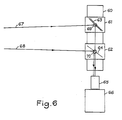
- FIG. 6 represents a fourth exemplary embodiment, implementing the known method of anaglyphs, and comprising a single camera 66 provided with a zoom 65 receiving the light coming from two directions of distinct views 67 and 68 respectively via d 'a deflection mirror 63 and a dichroic plate 64 placed on the optical axis of the camera 66.
- the mirror 63 is a vertical plane mirror rotating around a vertical axis under the action of an axis 69 analogous to axis 7 of the first exemplary embodiment.
- the dichroic blade 64 is plane and vertical, and it rotates around a vertical axis under the action of an axis 70 similar to the axis 8 of the first example.
- the axes 69 and 70 are carried by supports 61 and 62 similar to the supports 5 and 6 of the first example, driven by a device 60 for controlling the base and for controlling the convergence. analogous to that described in the first example.
- the optical axis of the camera 66 is in the extension of the direction of translation of the supports 61 and 62. When the convergence is zero the mirror 63 and the blade 64 are parallel and make an angle of 45 ° relative to the axis optic of the camera 66. The latter is fixed relative to the servo device 60.
- the invention is not limited to the embodiments described above, many variants are within the reach of those skilled in the art because there are many optical devices making it possible to take pictures with a variable base and a variable convergence, and these devices are in general easy to adapt to control the settings of the base and the convergence, by a device similar to that described for the first example.
- the invention applies to stereoscopic shooting for cinema and television in relief.
Landscapes
- Engineering & Computer Science (AREA)
- Multimedia (AREA)
- Signal Processing (AREA)
- Physics & Mathematics (AREA)
- Spectroscopy & Molecular Physics (AREA)
- General Physics & Mathematics (AREA)
- Stereoscopic And Panoramic Photography (AREA)
- Testing, Inspecting, Measuring Of Stereoscopic Televisions And Televisions (AREA)
Claims (9)
Applications Claiming Priority (2)
| Application Number | Priority Date | Filing Date | Title |
|---|---|---|---|
| FR8320292 | 1983-12-19 | ||
| FR8320292A FR2561400B3 (fr) | 1983-12-19 | 1983-12-19 | Dispositif de prise de vues stereoscopiques a base variable |
Publications (3)
| Publication Number | Publication Date |
|---|---|
| EP0146476A2 EP0146476A2 (de) | 1985-06-26 |
| EP0146476A3 EP0146476A3 (en) | 1985-07-24 |
| EP0146476B1 true EP0146476B1 (de) | 1988-06-15 |
Family
ID=9295310
Family Applications (1)
| Application Number | Title | Priority Date | Filing Date |
|---|---|---|---|
| EP84402607A Expired EP0146476B1 (de) | 1983-12-19 | 1984-12-14 | Vorrichtung für Stereoaufnahmen mit einem die Basis bestimmenden System |
Country Status (3)
| Country | Link |
|---|---|
| EP (1) | EP0146476B1 (de) |
| DE (1) | DE3472171D1 (de) |
| FR (1) | FR2561400B3 (de) |
Cited By (2)
| Publication number | Priority date | Publication date | Assignee | Title |
|---|---|---|---|---|
| DE4320110A1 (de) * | 1993-06-17 | 1994-12-22 | Pietzsch Ibp Gmbh | Verfahren zum Betreiben eines Stereo-Sichtsystems sowie Stereo-Sichtsystem mit zwei Sichtkanälen |
| DE4410358A1 (de) * | 1994-03-25 | 1995-09-28 | Rbt Raumbildtechnik Gmbh | Stereokamera |
Families Citing this family (21)
| Publication number | Priority date | Publication date | Assignee | Title |
|---|---|---|---|---|
| FR2593935B1 (fr) * | 1986-02-03 | 1989-11-17 | Drouard Gabriel | Procede et dispositif de formation d'images stereoscopiques |
| FR2599579A1 (fr) * | 1986-05-30 | 1987-12-04 | Electricite De France | Dispositif de prise de vues pour television en couleur et en relief. |
| US4815819A (en) * | 1987-04-30 | 1989-03-28 | Christopher A. Mayhew | Method for obtaining images for use in displaying a three-dimensional illusion and related image recording medium |
| AU617431B2 (en) * | 1988-03-07 | 1991-11-28 | Sharp Kabushiki Kaisha | Interlocked zooming apparatus |
| JPH01246989A (ja) * | 1988-03-29 | 1989-10-02 | Kanji Murakami | 立体撮像ビデオカメラ |
| US5253302A (en) * | 1989-02-28 | 1993-10-12 | Robert Massen | Method and arrangement for automatic optical classification of plants |
| JPH0666968B2 (ja) * | 1990-08-10 | 1994-08-24 | 幹次 村上 | 立体ビデオ撮像装置 |
| DE4129510C1 (de) * | 1991-09-05 | 1992-05-21 | Kernforschungszentrum Karlsruhe Gmbh, 7500 Karlsruhe, De | |
| WO1994010604A1 (en) * | 1992-10-29 | 1994-05-11 | Aea O´Donnell, Inc. | Automated stereoscopic image acquisition and storage system |
| FR2699296B1 (fr) * | 1992-12-14 | 1994-12-30 | Olivier Boute | Dispositif de prise de vues triscopiques. |
| JP2721808B2 (ja) * | 1994-10-18 | 1998-03-04 | 稔 稲葉 | ステレオカメラ |
| FR2735936B1 (fr) | 1995-06-22 | 1997-08-29 | Allio Pierre | Procede d'acquisition d'images autostereoscopiques simulees |
| FR2795531B1 (fr) * | 1999-06-23 | 2002-12-20 | Minoru Inaba | Appareil photographique stereoscopique comportant un capteur de donnees concernant la distance focale |
| US7298484B2 (en) * | 2004-03-10 | 2007-11-20 | Raytheon Company | Dual-band sensor system utilizing a wavelength-selective beamsplitter |
| BE1018798A3 (fr) * | 2009-06-23 | 2011-09-06 | Visee Christian | Dispositif d'acquisition d'images tridimensionnelles stereoscopiques. |
| DE102011016171B4 (de) * | 2011-04-05 | 2012-12-27 | 3Ality Digital Systems, Llc | Verfahren zum Ausrichten einer 3D-Kamera und Verfahren zum Steuern einer 3D-Kamera während des Filmens |
| DE102013226654A1 (de) * | 2013-12-19 | 2015-06-25 | Robert Bosch Gmbh | Optisches Stereo-System |
| US10299880B2 (en) | 2017-04-24 | 2019-05-28 | Truevision Systems, Inc. | Stereoscopic visualization camera and platform |
| US10917543B2 (en) | 2017-04-24 | 2021-02-09 | Alcon Inc. | Stereoscopic visualization camera and integrated robotics platform |
| US11083537B2 (en) | 2017-04-24 | 2021-08-10 | Alcon Inc. | Stereoscopic camera with fluorescence visualization |
| CN116300039B (zh) * | 2023-03-09 | 2026-03-03 | 成都弘照科技有限公司 | 一种变基线交相角摄影的数字影像立体显微系统及方法 |
Family Cites Families (4)
| Publication number | Priority date | Publication date | Assignee | Title |
|---|---|---|---|---|
| GB888317A (en) * | 1959-10-26 | 1962-01-31 | Pye Ltd | Improvements in television cameras |
| US4418993A (en) * | 1981-05-07 | 1983-12-06 | Stereographics Corp. | Stereoscopic zoom lens system for three-dimensional motion pictures and television |
| FR2516334A1 (fr) * | 1981-11-09 | 1983-05-13 | Corviole Raymond | Procede de television en relief totalement compatible en deux dimensions, sans alteration des couleurs, applicable au standard secam |
| DE3226703A1 (de) * | 1981-12-31 | 1983-07-07 | 3D Video Corp., 91016 North Hollywood, Calif. | Stereoskopisches bildsystem |
-
1983
- 1983-12-19 FR FR8320292A patent/FR2561400B3/fr not_active Expired
-
1984
- 1984-12-14 EP EP84402607A patent/EP0146476B1/de not_active Expired
- 1984-12-14 DE DE8484402607T patent/DE3472171D1/de not_active Expired
Cited By (3)
| Publication number | Priority date | Publication date | Assignee | Title |
|---|---|---|---|---|
| DE4320110A1 (de) * | 1993-06-17 | 1994-12-22 | Pietzsch Ibp Gmbh | Verfahren zum Betreiben eines Stereo-Sichtsystems sowie Stereo-Sichtsystem mit zwei Sichtkanälen |
| DE4410358A1 (de) * | 1994-03-25 | 1995-09-28 | Rbt Raumbildtechnik Gmbh | Stereokamera |
| DE4410358C2 (de) * | 1994-03-25 | 1998-03-19 | Rbt Raumbildtechnik Gmbh | Stereokamera |
Also Published As
| Publication number | Publication date |
|---|---|
| FR2561400A1 (fr) | 1985-09-20 |
| FR2561400B3 (fr) | 1987-04-10 |
| DE3472171D1 (en) | 1988-07-21 |
| EP0146476A3 (en) | 1985-07-24 |
| EP0146476A2 (de) | 1985-06-26 |
Similar Documents
| Publication | Publication Date | Title |
|---|---|---|
| EP0146476A2 (de) | Vorrichtung für Stereoaufnahmen mit einem die Basis bestimmenden System | |
| US6701081B1 (en) | Dual camera mount for stereo imaging | |
| EP3128894B1 (de) | Phoropter und verfahren zur messung der refraktion mittels eines phoropters des besagten typs | |
| EP2220420B1 (de) | Kamerahaltemodul und vorrichtung zum schiessen von reliefbildern | |
| FR2769449A1 (fr) | Systeme de prise de vues et de reproduction stereoscopique | |
| JP2017122791A (ja) | 光学制御装置、光学機器および光学制御プログラム | |
| JPH05260360A (ja) | 写真測量用オートフォーカスccdカメラ | |
| US7391966B2 (en) | Selective focus system for use in photography | |
| FR2638540A1 (en) | Camera with zoom lens | |
| EP1673651A2 (de) | Betrachtungseinrichtung mit orientierungs-abbildungs-einrichtung | |
| JP2004510173A (ja) | 3−d画像を作成する装置 | |
| JPS62180338A (ja) | 焦点調節装置 | |
| FR2599579A1 (fr) | Dispositif de prise de vues pour television en couleur et en relief. | |
| FR2549247A1 (fr) | Nouveau procede pour obtenir le relief cinematographique avec un seul objectif, applicable au cinematographe, aux appareils de prises de vues de la television, a ceux de la radiocinematographie et a l'optique en general | |
| FR2794872A1 (fr) | Dispositif de commande d'un objectif a focale variable et dispositif a focale variable | |
| JP5504716B2 (ja) | 撮像装置 | |
| FR2705795A1 (fr) | Dispositif miniaturisé de visualisation d'image d'objets mobiles, en particulier pour simulateur à écran sphérique de faibles dimensions. | |
| BE1018798A3 (fr) | Dispositif d'acquisition d'images tridimensionnelles stereoscopiques. | |
| EP4390500A1 (de) | Bilderfassungssystem zur biometrischen iriserkennung einer person | |
| FR2522832A1 (fr) | Systeme optique a reflexions pouvant etre adapte a l'appareil photographique, camera ou television permettant d'obtenir la reduction et la reproduction d'un espace avec perception du relief | |
| JPH07170433A (ja) | カメラ | |
| BE649052A (de) | ||
| FR2666156A2 (fr) | Procede et dispositifs pour enregistrer des images perceptibles dans les trois dimensions et application d'un tel procede. | |
| FR2616923A1 (fr) | Dispositif modulaire pour la prise de vues stereoscopique | |
| FR2509481A1 (fr) | Visionneuse stereoscopique |
Legal Events
| Date | Code | Title | Description |
|---|---|---|---|
| PUAI | Public reference made under article 153(3) epc to a published international application that has entered the european phase |
Free format text: ORIGINAL CODE: 0009012 |
|
| PUAL | Search report despatched |
Free format text: ORIGINAL CODE: 0009013 |
|
| AK | Designated contracting states |
Designated state(s): BE DE FR GB |
|
| AK | Designated contracting states |
Designated state(s): BE DE FR GB |
|
| 17P | Request for examination filed |
Effective date: 19851209 |
|
| 17Q | First examination report despatched |
Effective date: 19870204 |
|
| GRAA | (expected) grant |
Free format text: ORIGINAL CODE: 0009210 |
|
| AK | Designated contracting states |
Kind code of ref document: B1 Designated state(s): DE FR GB |
|
| REF | Corresponds to: |
Ref document number: 3472171 Country of ref document: DE Date of ref document: 19880721 |
|
| GBT | Gb: translation of ep patent filed (gb section 77(6)(a)/1977) | ||
| PLBE | No opposition filed within time limit |
Free format text: ORIGINAL CODE: 0009261 |
|
| STAA | Information on the status of an ep patent application or granted ep patent |
Free format text: STATUS: NO OPPOSITION FILED WITHIN TIME LIMIT |
|
| RAP4 | Party data changed (patent owner data changed or rights of a patent transferred) |
Owner name: THOMSON-CSF |
|
| 26N | No opposition filed | ||
| PGFP | Annual fee paid to national office [announced via postgrant information from national office to epo] |
Ref country code: DE Payment date: 19991229 Year of fee payment: 17 |
|
| PGFP | Annual fee paid to national office [announced via postgrant information from national office to epo] |
Ref country code: GB Payment date: 20001109 Year of fee payment: 17 |
|
| PGFP | Annual fee paid to national office [announced via postgrant information from national office to epo] |
Ref country code: FR Payment date: 20001215 Year of fee payment: 17 |
|
| PG25 | Lapsed in a contracting state [announced via postgrant information from national office to epo] |
Ref country code: GB Free format text: LAPSE BECAUSE OF NON-PAYMENT OF DUE FEES Effective date: 20011214 |
|
| REG | Reference to a national code |
Ref country code: GB Ref legal event code: IF02 |
|
| PG25 | Lapsed in a contracting state [announced via postgrant information from national office to epo] |
Ref country code: DE Free format text: LAPSE BECAUSE OF NON-PAYMENT OF DUE FEES Effective date: 20020702 |
|
| GBPC | Gb: european patent ceased through non-payment of renewal fee |
Effective date: 20011214 |
|
| PG25 | Lapsed in a contracting state [announced via postgrant information from national office to epo] |
Ref country code: FR Free format text: LAPSE BECAUSE OF NON-PAYMENT OF DUE FEES Effective date: 20020830 |
|
| REG | Reference to a national code |
Ref country code: FR Ref legal event code: ST |