EP0146531B1 - Sécheur à couche mince pour des produits coulants - Google Patents
Sécheur à couche mince pour des produits coulants Download PDFInfo
- Publication number
- EP0146531B1 EP0146531B1 EP84890245A EP84890245A EP0146531B1 EP 0146531 B1 EP0146531 B1 EP 0146531B1 EP 84890245 A EP84890245 A EP 84890245A EP 84890245 A EP84890245 A EP 84890245A EP 0146531 B1 EP0146531 B1 EP 0146531B1
- Authority
- EP
- European Patent Office
- Prior art keywords
- drier
- area
- distributor ring
- rotor shaft
- wall
- Prior art date
- Legal status (The legal status is an assumption and is not a legal conclusion. Google has not performed a legal analysis and makes no representation as to the accuracy of the status listed.)
- Expired
Links
- 239000010409 thin film Substances 0.000 title description 12
- 239000000428 dust Substances 0.000 claims abstract description 47
- 238000001035 drying Methods 0.000 claims abstract description 29
- 239000002245 particle Substances 0.000 claims abstract description 28
- 239000007789 gas Substances 0.000 claims abstract description 18
- 239000007787 solid Substances 0.000 claims abstract description 18
- 239000000126 substance Substances 0.000 claims abstract description 10
- 230000009969 flowable effect Effects 0.000 claims abstract description 6
- 230000000149 penetrating effect Effects 0.000 claims abstract 2
- 239000004033 plastic Substances 0.000 claims description 23
- 229920003023 plastic Polymers 0.000 claims description 23
- 239000000463 material Substances 0.000 claims description 16
- 238000009833 condensation Methods 0.000 claims description 8
- 230000005494 condensation Effects 0.000 claims description 8
- 229920000034 Plastomer Polymers 0.000 claims description 7
- 239000000919 ceramic Substances 0.000 claims description 5
- 239000011810 insulating material Substances 0.000 claims description 4
- 229920001296 polysiloxane Polymers 0.000 claims description 4
- 229920002430 Fibre-reinforced plastic Polymers 0.000 claims description 2
- 239000010425 asbestos Substances 0.000 claims description 2
- 239000000835 fiber Substances 0.000 claims description 2
- 239000011151 fibre-reinforced plastic Substances 0.000 claims description 2
- 229910052895 riebeckite Inorganic materials 0.000 claims description 2
- 230000001174 ascending effect Effects 0.000 claims 2
- 239000011888 foil Substances 0.000 claims 1
- 239000011490 mineral wool Substances 0.000 claims 1
- 239000002609 medium Substances 0.000 description 13
- 238000010438 heat treatment Methods 0.000 description 8
- 239000011248 coating agent Substances 0.000 description 6
- 238000000576 coating method Methods 0.000 description 6
- 238000001704 evaporation Methods 0.000 description 6
- 238000009413 insulation Methods 0.000 description 6
- 238000000926 separation method Methods 0.000 description 6
- 229910000831 Steel Inorganic materials 0.000 description 5
- 230000008020 evaporation Effects 0.000 description 5
- 239000010959 steel Substances 0.000 description 5
- 230000015572 biosynthetic process Effects 0.000 description 4
- 229920002313 fluoropolymer Polymers 0.000 description 3
- 239000007788 liquid Substances 0.000 description 3
- 239000002184 metal Substances 0.000 description 3
- 230000002093 peripheral effect Effects 0.000 description 3
- 230000008021 deposition Effects 0.000 description 2
- 229920001971 elastomer Polymers 0.000 description 2
- 239000004744 fabric Substances 0.000 description 2
- 239000010419 fine particle Substances 0.000 description 2
- 238000005457 optimization Methods 0.000 description 2
- 239000006223 plastic coating Substances 0.000 description 2
- 230000000630 rising effect Effects 0.000 description 2
- 239000011343 solid material Substances 0.000 description 2
- 229910001220 stainless steel Inorganic materials 0.000 description 2
- 239000010935 stainless steel Substances 0.000 description 2
- 206010044565 Tremor Diseases 0.000 description 1
- 230000001133 acceleration Effects 0.000 description 1
- 230000002730 additional effect Effects 0.000 description 1
- 230000003750 conditioning effect Effects 0.000 description 1
- 238000001816 cooling Methods 0.000 description 1
- 238000005260 corrosion Methods 0.000 description 1
- 230000007797 corrosion Effects 0.000 description 1
- 230000000694 effects Effects 0.000 description 1
- 239000000806 elastomer Substances 0.000 description 1
- 239000013536 elastomeric material Substances 0.000 description 1
- 239000012526 feed medium Substances 0.000 description 1
- 239000010408 film Substances 0.000 description 1
- 239000006260 foam Substances 0.000 description 1
- 239000003365 glass fiber Substances 0.000 description 1
- 239000011491 glass wool Substances 0.000 description 1
- 239000012774 insulation material Substances 0.000 description 1
- 230000014759 maintenance of location Effects 0.000 description 1
- 238000000034 method Methods 0.000 description 1
- 238000005192 partition Methods 0.000 description 1
- 238000003825 pressing Methods 0.000 description 1
- 238000007790 scraping Methods 0.000 description 1
- 238000007493 shaping process Methods 0.000 description 1
- 229920003002 synthetic resin Polymers 0.000 description 1
- 239000000057 synthetic resin Substances 0.000 description 1
- 239000010891 toxic waste Substances 0.000 description 1
Images

Classifications
-
- B—PERFORMING OPERATIONS; TRANSPORTING
- B01—PHYSICAL OR CHEMICAL PROCESSES OR APPARATUS IN GENERAL
- B01D—SEPARATION
- B01D1/00—Evaporating
- B01D1/22—Evaporating by bringing a thin layer of the liquid into contact with a heated surface
- B01D1/222—In rotating vessels; vessels with movable parts
- B01D1/223—In rotating vessels; vessels with movable parts containing a rotor
- B01D1/225—In rotating vessels; vessels with movable parts containing a rotor with blades or scrapers
- B01D1/226—In rotating vessels; vessels with movable parts containing a rotor with blades or scrapers in the form of a screw or with helical blade members
-
- F—MECHANICAL ENGINEERING; LIGHTING; HEATING; WEAPONS; BLASTING
- F26—DRYING
- F26B—DRYING SOLID MATERIALS OR OBJECTS BY REMOVING LIQUID THEREFROM
- F26B17/00—Machines or apparatus for drying materials in loose, plastic, or fluidised form, e.g. granules, staple fibres, with progressive movement
- F26B17/18—Machines or apparatus for drying materials in loose, plastic, or fluidised form, e.g. granules, staple fibres, with progressive movement with movement performed by rotating helical blades or other rotary conveyors which may be heated moving materials in stationary chambers, e.g. troughs
- F26B17/22—Machines or apparatus for drying materials in loose, plastic, or fluidised form, e.g. granules, staple fibres, with progressive movement with movement performed by rotating helical blades or other rotary conveyors which may be heated moving materials in stationary chambers, e.g. troughs the axis of rotation being vertical or steeply inclined
-
- F—MECHANICAL ENGINEERING; LIGHTING; HEATING; WEAPONS; BLASTING
- F26—DRYING
- F26B—DRYING SOLID MATERIALS OR OBJECTS BY REMOVING LIQUID THEREFROM
- F26B25/00—Details of general application not covered by group F26B21/00 or F26B23/00
- F26B25/005—Treatment of dryer exhaust gases
- F26B25/007—Dust filtering; Exhaust dust filters
-
- F—MECHANICAL ENGINEERING; LIGHTING; HEATING; WEAPONS; BLASTING
- F26—DRYING
- F26B—DRYING SOLID MATERIALS OR OBJECTS BY REMOVING LIQUID THEREFROM
- F26B3/00—Drying solid materials or objects by processes involving the application of heat
- F26B3/18—Drying solid materials or objects by processes involving the application of heat by conduction, i.e. the heat is conveyed from the heat source, e.g. gas flame, to the materials or objects to be dried by direct contact
- F26B3/20—Drying solid materials or objects by processes involving the application of heat by conduction, i.e. the heat is conveyed from the heat source, e.g. gas flame, to the materials or objects to be dried by direct contact the heat source being a heated surface, e.g. a moving belt or conveyor
Definitions
- the invention relates to a dryer, in particular a vertical thin-film dryer, for drying flowable materials, which has a feed area, a heated drying area and a vapor-steam area and a rotor passing through these areas, the rotor shaft in the feed area having a rotating one close to it Dryer wall reaching distribution ring, with which the flowable substances fed in the feed area are distributed on the inside wall of the dryer and through its interior formed as a passage opening, the vapors and / or gases generated during the drying of the substances from the drying area located below the distribution ring in the above the distribution ring the vapor vapor area located.
- a rotary film column which works on the principle of partial evaporation and condensation and consists of a heatable column jacket in which there is a coolable vane rotor. On the wing rotor, between the wiper blades, there are horizontally extending constriction plates with respect to the rising steam flow.
- a rotating separation device is known from FR-A-1 047 794, in which the rising gases are passed through horizontal floors.
- US-A-3 654 981, 2208466 and GB-A-2 077 414 show conventional vaporizers also without means to improve the vapor-vapor separation efficiency.
- FR-A-2379305 shows scrapers for the wall of a thin film evaporator.
- DE-A-28 30 874 discloses a thin-film treatment apparatus, in particular thin-film evaporator, with a rotor with a shaft and a rotationally symmetrical one arranged around it.
- metric wall the rotor in the feed area of the material to be evaporated extending to the wall having essentially radial, elastically resilient stripping elements.
- the scraper elements are designed in sheet form in a manner known per se, these and the rotor being at least partially coated with an elastomeric material in order to prevent particles from being deposited thereon. It is also provided that the stripping elements are movably connected to the rotor.
- horizontal plates rotating with the rotor of an evaporator are known.
- thin layers of the medium to be dried are preferably applied continuously to heated surfaces, where the evaporable component, mostly with the additional action of vacuum, is converted into the gas phase. If necessary with thin-film evaporators, but always with thin-film dryers, a more or less stable layer of solid residues remains on the heating surface. This layer is continuously removed from the heating surface, resulting in the basic structure of a thin-layer dryer as follows.
- a heating surface arranged rotationally symmetrically around a rotor together with the stripping elements dries the medium introduced through a feed line in thin layers with the aid of the centrifugal forces generated by the rotor or a distributor ring.
- the dry residue is continuously removed from the heating surface by means of the scraper elements mounted on the rotor shaft inside the distributor ring.
- the solid material continuously removed from the heating surface trickles downward, so that the solid material collects and can be discharged.
- the structure of the rotor is particularly important for the trouble-free functioning of a dryer.
- a suitable rotor design ensures that the mostly fine-particle solids that arise during drying can be properly separated from the evaporating liquid medium in the drying area and discharged as quantitatively as possible from the drying area. In other words, it must be ensured that as far as possible no solid in the form of dust particles is entrained by the outgoing steam or gas and is only deposited in the peripheral systems of the dryer.
- the aim of the present invention is to design a dryer of the type mentioned at the outset in such a way that the demands placed on it can be met, namely to avoid that significant portions of the dry product in the form of dust particles are entrained by the outflowing steam or gas are discharged from the dryer.
- this is achieved in that in the vapor-vapor region of the dryer for holding back solid particles carried with vapor vapors in the dryer on the rotor shaft close to the dryer wall, dust-collecting elements are attached, which have inclined or perpendicular surfaces with respect to the rotor axis and with the rotor shaft are elastically connected or movably mounted on it and can be set into a shaking, oscillating and / or vibrating movement during operation by the rotation of the rotor shaft.
- the invention thus relates to a dryer, in particular a vertical thin-film dryer, whose task compared to the usual dryers is to retain the dust-like fines that occur during the drying process, which are normally discharged with the vapors being drawn off, as quantitatively as possible in the dryer housing, with the actual dry product, together with this from the dryer according to the system execute and thus increase the yield.
- the vertically mounted cylindrical dryer jacket is divided into a lower heated dryer area and an unheated steam vapor area above it, with the feed area between these zones, where the material to be dried is fed into the system.
- the rotor of the dryer is mounted in a rotationally symmetrical manner over the entire length inside the cylindrical dryer jacket.
- the rotor elements required for the function are attached to the rotor axis in accordance with the three zones (from bottom to top: dryer area, infeed area, steam / vapor area).
- these are stripping elements that are necessary to spread thin layers of the medium applied by the centrifugal forces of the rotor via the distributor ring onto the hot dryer jacket and to remove them continuously after drying.
- the removed dry product trickles downwards when the dryer is built up vertically, from where it is collected and discharged.
- the steam flowing in from the dryer area via the distributor ring is made to have increased turbulence by dust separating elements according to the invention, which have moveable fastened to the rotor shaft and have inclined surfaces, the dust particles being coarsened and deposited on the dust separating elements or trickling downwards.
- the vibrations caused by the stripping elements attached to the rotor in the dryer area are transmitted via the rotor as shaking movements to the movable dust separating elements, so that the dust deposits deposited here are shaken off and trickled downwards.
- the solid components thus obtained from the dusts return through the dry inner area of the distributor ring equipped according to the invention, or outside via the feed zone, back into the dryer area and are combined with the dry product produced.
- Appropriate temperature setting in the workflow prevents the formation of droplets as the steam rises and thus the formation of moist lumps with the dusts carried along in the steam / vapor area, so that the measures according to the invention achieve the increased dry product yield.
- the dryer according to the invention thus differs from its intended use or its task and also from the structure of the known devices, none of which can be used for the separation of solid particles; Coarsening of the dust particles and shaking the particles back into the dry area cannot be carried out with them.
- the vapors vapor space no separating elements for dust particles are provided in the known devices, so that the basic structure of these devices is completely different.
- the outflowing steam is given increased turbulence or the dust is subjected to centrifugal acceleration, so that the dry product particles can be intercepted, coarsened and returned to the actual drying area.
- the interior and / or the inner walls of the distributor ring with respect to its outer wall are heat-insulated and / or heatable and / or the inner walls of the distributor ring consist of heat-insulating material.
- This inventive design of the distributor ring in the feed zone of the dryer prevents the cold medium introduced from condensing the outflowing steam and / or gas; thus the interior or the outflow openings for the steam or the gas can be inside the Distribution ring from damp deposits are kept free and the steam or gas flow from this area unhindered into the vapor steam area.
- FIGS. 2, 2a, 3, 3a, 4, 4a and 4b show different embodiments of a distributor ring, partly in section
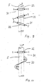
- FIGS. 5-12 show different embodiments of dust separating elements.
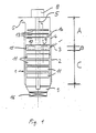
- a thin-film dryer 1 shows a thin-film dryer 1, which is advantageously constructed vertically. is and usually has a cylindrical peripheral shape.
- a heatable cylindrical dryer jacket 2 has a medium feed opening 3 and is extended above it.
- This extension 4 can also be cylindrical, but can also have a steep conical shape that widens upwards, which enables the rotor or the rotor shaft 5 to be easily removed upwards.
- This extension 4, which can correspond to approximately 20-50% of the total length of the dryer 1, does not have to be heated, it is sufficient effective insulation against the environment, which condenses the medium vapors or gases inside or on the. Inner wall of extension 4 prevented. At the upper end of this extension there is a steam outlet 6.
- the end is formed by a corresponding flat or curved flange with a bushing for the rotor shaft 5, which is set in rotation by a drive 8 from above.
- the rotor which extends over the entire length of the dryer 1, has a functional function in the three functional areas of the dryer, the drying area C, the feed-in area B and the vapor vapor area A and consists of the rotor shaft 5, the stripping elements 11 in the drying area C, a distributor ring 10, which is at least partially located in the feed area B, and dust separating elements 13 in the steam area A.
- the lower, heated, actual drying area C, in which the stripping elements 11 are arranged, is not discussed in detail in connection with the present invention, since a corresponding training of the rotor in this area is known from US-A-4 208 243.
- the vapors and / or gases produced in the heated drying area C are discharged upwards from this and pass through the distribution ring 10, which is constantly cooled by the cold feed medium, which ensures that the medium or the substances to be dried are applied as evenly as possible in thin layers on the Heating jacket 2 of the dryer 1 can be applied.
- the steam or gases generally flow through the inner open area of the distributor ring 10 (arrow 12) and it has hitherto been difficult to avoid that portions of the steam condense and, with the fine portions of the dry product carried along, lead to a narrowing of the through-openings in the distributor ring 10, which disrupts the operation However, this is avoided by the formation of the distributor ring 10.
- the rotor shaft 5 is equipped with dust separating elements 13 (shown schematically in FIG. 1) which generate increased turbulence in the steam flow and which, by suitable shaping and choice of material, ensure that the dust particles largely agglomerate in the steam space 14 and deposit on the wall of the dryer 1 and can be returned to the lower area.
- the formation of the distributor ring 10 in the feed area B and the dust separating elements 13 in the steam area A have the purpose of concentrating the dried solid as quantitatively as possible in the dry area C and in the desired manner, usually in accordance with the gravitation, into a drying room 9 for dry solid bring from which the solid is discharged through a lock 16. This prevents the steam discharged upwards from the dryer 1 from carrying substantial amounts of solids and thus excessively loading the subsequent steam lines, vapor washer, condenser, etc. A requirement that must be taken into account especially when drying and conditioning bio-harmful or toxic waste.
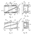
- FIGS. 2 and 3 show exemplary embodiments of the distributor ring 10, which allow the steam or gas to exit the heated drying area C into the steam area A of the dryer 1 as freely as possible.
- a distributor ring 10 consists of a supporting sleeve part 17 fastened to the rotor shaft 5, from which support or webs 18 extend, which carry a ring part 19, which in turn carries a distributor element 20.
- the ring part 19 can be made of corrosion-resistant, thermostable, poorly heat-conducting plastics, e.g. As fluoroplastics, silicone plastics, which are advantageously reinforced with fibers and / or fabrics to increase the mechanical stability (z. B. glass fibers), be made entirely or partially or coated, clad or coated with it.
- fluoroplastics e.g. As fluoroplastics, silicone plastics, which are advantageously reinforced with fibers and / or fabrics to increase the mechanical stability (z. B. glass fibers), be made entirely or partially or coated, clad or coated with it.
- the ring portion 19 of z. B. 3 to 6 spoke-shaped on the rotor shaft 5 fixed (z. B. welded, screwed) or outgoing from the sleeve part 17 webs 18 is carried.
- the attachment of the ring member 19 is carried out, for. B. by sliding the ring member 19 onto the vertical webs 18, which engage in groove-shaped recesses in the ring member 19. Up and down, the ring part 19 is on the end face covered a steel ring 21, which also engages with slots in the webs 18 and is fixed against slipping out of the webs 18 with screwed or cotter pins 22.
- the surfaces of the metal parts inside the distributor ring 10, ie the rotor shaft 5, the webs 18, the sleeve 17, the steel rings 21 and the inner surfaces of the ring part 19, if this is made of metal, are provided with a plastic layer 23, for. B. fluoroplastic, or coated with a ceramic layer.
- a plastic layer 23 for. B. fluoroplastic, or coated with a ceramic layer.
- On the outer periphery of the ring member 19 are expediently attached to the dryer jacket 2 reaching, helically arranged stripping elements 20, which force the conveyed medium from the feed area 13 down into the heated drying area C and placed on the ring part 19, z. B. screwed, riveted or integrated in pre-milled grooves and fixed.
- FIG. 3 and 3a show a further possible embodiment of a distributor ring 10.
- the ring part 19 consists of a plastic body which has screw-shaped recesses 20 'on the outer cylinder surface which distribute the medium in a functionally appropriate manner.
- Crosspieces 18 are made, for example, by screws 24 or rivets, where the crosspieces 18 can be provided with tabs or have a frame shape and are connected to the ring body 19.
- all metal surfaces of the rotor shaft 5 and the supporting webs 18 are provided with a suitable coating in order to avoid steam condensation and solid deposition.
- the interior of the distributor ring 10 is thermally insulated by the plastic body forming the annular body 19 and by the coating of the webs 18 against cooling by the medium fed in, thus preventing condensation of the vapor vapors on cold surfaces.
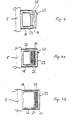
- FIG. 4 shows a distributor ring 10 with an annular body 19 which is supported by metallic webs 18 covered with a plastic layer 23 and which has chambers or cavities 25 running around in its interior for thermal insulation.
- FIG. 4a shows a distributor ring 10, the metallic ring body 19 or the outside of which is coated with a layer 23 of plastic or ceramic.
- an annular body with one or more chambers 26 is arranged, the thermal insulation materials, for. B. glass wool, synthetic resin foam, asbestos, and. s. w. contain.
- the webs 18, the sleeve 17 and optionally the rotor shaft 5 are in turn provided with a coating 23 made of plastic or ceramic.
- FIG. 4b shows a distributor ring 10 with a metallic ring body 19 carried by metallic webs 18, the webs 18 and the outside of the annular body 19 being provided with a coating 23.
- a partition or shield 27 made of plastic or ceramic is also carried by the webs 18, a heat insulation layer 26 being arranged between the ring body 19 and the shield 27.
- a rubber-elastic plastic coating 23 has in addition to the thermal insulation the advantage that sticking of condensed particles is prevented by the elasticity of the plastic coating and the particles by their own movement, for. B. vibration, the coating fall off.
- the thickness of the coating or thermal insulation is dimensioned such that the temperature of the interior of the distributor ring is raised such that it is above the condensation temperature of the vapors or gases at the pressure prevailing in the dryer.
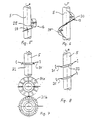
- FIG. 5-12 show examples of the equipment of the rotor in the vapor-vapor region A, as are provided according to the invention for separating dust particles in the outflowing vapors and / or gases.
- Fig. 5 shows an example of dust separating elements 13, which of mechanically sufficiently stable helically arranged segments 29, z. B. are formed from plastic-coated steel sheet or fiber-reinforced plastomers, which are attached to the rotor shaft 5 with adjustable elastic or resilient brackets 28 and extend close to the dryer wall 2.
- the edge zones of the segments 29 are set in a trembling motion by the movement of the rotor shaft 5, as a result of which dust particles that strike are separated from the turbulent steam flow and can be returned to the actual drying area C via the distributor ring 10.
- the brackets 28 can be coated like the segments 29.
- the areas of the segments 29 increase in the direction of the direction of rotation of the rotor shaft 5, wherein the increase can be changed by rotating the segments 29.
- FIG. 6 A similar embodiment is shown in FIG. 6.
- a strip 30 fastened helically to the rotor shaft 5 and reaching a distance from the dry wall 2 by a gap is not divided into relatively short segments as in FIG. B. in about 2-6 turns over the entire length of the rotor shaft 5 in the steam region A, it to reduce its stiffness, possibly z. B. can be slit or interrupted at 1 to 3 points.
- the attachment or the brackets 28 or the inserts for the brackets 28 on the rotor shaft 5 are, if possible, not rigid.
- Slotted brackets 28, into which the spiral strip or strips 30 are inserted and fixed can, as described above, be connected to the inserts screwed into or welded to the rotor shaft 5 via a joint or a short spiral spring or a rubber bolt, thereby shaking off trapped dust is promoted during operation and its combination with the bulk of the dry product is made possible.
- two to three and also more spiral strips 30 can be mounted in parallel or offset or parallel to one another. will.
- FIG. 7 Another possible embodiment of the dust separating elements 13 is shown in FIG. 7.
- Openwork disks 31 made of plastic-coated steel sheet or of sufficiently mechanically stable plastomers are slotted (31 a) or perforated (31 b) and fastened to the rotor shaft 5 with screwed or welded advantageously resilient tabs 32 in such a way that they are slightly curved or horizontally close to the Reach dryer wall 2.
- a type of baffle can be provided through the offset openings in overlapping disks 31a, 31b in order to increase the turbulence of the outflowing steam.
- the disks 31 are designed so that the edges directed against the dryer wall are relatively thin, so that during operation the dust particles deposited on a disk 31 are loosened by vibration and directed to the dryer wall 2 by centrifugal force. From there, the dust particles are returned to the actual drying area C, as already described above.
- the upper part of the rotor shaft 5 according to FIG. 8 is in principle equipped with the same disks 31 as the rotor shaft 5 in FIG. 7. Since the disks 31 are fastened in inclined brackets 33 with respect to the axis of the rotor shaft 5, this results during the rotation the tumbling movement a particularly intense turbulence and an additional up-down movement to the vibration mentioned above. Deposited dust particles are thereby shaken off again as coarsened grains and, as already described, conveyed downward over the dryer wall to the main amount of the dry product.
- FIG. 9 shows the combination of horizontal brackets 32 and brackets 33 which are at an angle to one another, equipped with disks 31 which reach close to the dryer wall 2 but do not touch them the rotor shaft 5 and the horizontal, advantageously slightly curved disks 31 are arranged in the upper and lower region thereof, a particularly advantageous combination results.
- the lower disk 31 prevents dust particles from the rotor shaft 5 from reaching the inner evaporation opening of the distributor ring 10, the upper disk 31 particularly advantageously blocks the escape of the finest dust particles into the evaporation or vapor line of the dryer 1.
- the disk perforation or slitting can be carried out by pressing, wherein advantageously perforated or slot edges lagging in the direction of rotation are raised in relation to the plane of the disk.
- 11 and 12 show dust separating elements 13, which are formed by vanes 34, which can be pivoted and are fastened to the rotor shaft 5 with joints in screwed-on or welded-on brackets 28 such that they are directed against the dryer wall 2 by rotation by the centrifugal force and reach close to them.
- Their inclination with respect to a plane perpendicular to the rotor shaft 5 and in the direction of rotation of the rotor shaft 5 can be selected and can range from a vertical position to an oblique position to a horizontal position.
- Through an overlapping arrangement of the wings 34 is in the lower part of the steam. rich A the interior of the distributor ring 10 is shielded so that the steam outlet openings can no longer be narrowed from solid deposits.
- a downward and outward movement of the dust particles can be achieved by a smaller inclination of the wings 34.
- downward and outward movement of the dust particles can be achieved by slightly inclining the wings 34.
- the direct steam outlet can be disturbed again by a horizontal arrangement of the vanes 34 and the escape of the solid particles into the evaporation line 6 can be prevented as far as possible.
- the material for the wings 34 is recommended to use the material for the wings 34 with stainless steel or fabric or fiber-reinforced plastic coated with fluoroplastics, in order to additionally prevent and hold dry products from sticking to the blades which vibrate during the working process, advantageously due to the resilient holders to avoid steam condensation.
- the rotor shaft 5 itself at least partially with plastomers, fluorinated plastics or silicone to coat plastics so that the rotor shaft 5 as well as the dust separating elements 13 and the distributor ring 10 can be kept largely free of deposits.
- the optimization of the vertical thin-film dryer according to the invention is not limited to the examples given.
- a combination of suitable heating with simultaneous thermal insulation of the distributor interior is a particularly advantageous embodiment variant of the dryer distributor ring 10 in question.
Landscapes
- Engineering & Computer Science (AREA)
- Mechanical Engineering (AREA)
- General Engineering & Computer Science (AREA)
- Chemical & Material Sciences (AREA)
- Chemical Kinetics & Catalysis (AREA)
- Life Sciences & Earth Sciences (AREA)
- Microbiology (AREA)
- Drying Of Solid Materials (AREA)
- Processing And Handling Of Plastics And Other Materials For Molding In General (AREA)
Claims (14)
Applications Claiming Priority (2)
| Application Number | Priority Date | Filing Date | Title |
|---|---|---|---|
| AT4398/83 | 1983-12-16 | ||
| AT0439883A AT388112B (de) | 1983-12-16 | 1983-12-16 | Trockner, insbesondere vertikaler duennschichttrockner |
Publications (3)
| Publication Number | Publication Date |
|---|---|
| EP0146531A2 EP0146531A2 (fr) | 1985-06-26 |
| EP0146531A3 EP0146531A3 (en) | 1986-02-12 |
| EP0146531B1 true EP0146531B1 (fr) | 1988-10-19 |
Family
ID=3563475
Family Applications (1)
| Application Number | Title | Priority Date | Filing Date |
|---|---|---|---|
| EP84890245A Expired EP0146531B1 (fr) | 1983-12-16 | 1984-12-13 | Sécheur à couche mince pour des produits coulants |
Country Status (3)
| Country | Link |
|---|---|
| EP (1) | EP0146531B1 (fr) |
| AT (2) | AT388112B (fr) |
| DE (1) | DE3474636D1 (fr) |
Cited By (1)
| Publication number | Priority date | Publication date | Assignee | Title |
|---|---|---|---|---|
| CN108813672A (zh) * | 2018-05-17 | 2018-11-16 | 兴化市绿禾食品有限公司 | 一种循环式蔬菜脱水烘干装置 |
Families Citing this family (4)
| Publication number | Priority date | Publication date | Assignee | Title |
|---|---|---|---|---|
| FR2599022A1 (fr) * | 1986-05-23 | 1987-11-27 | Solamat | Appareil auto-nettoyant pour le traitement des eaux polluees. |
| EP0609498A1 (fr) * | 1992-10-28 | 1994-08-10 | Anneliese Cramer Trocknerbau | Dessiccateur pour granulat de matière thermodurcissable |
| US8997554B2 (en) | 2012-04-20 | 2015-04-07 | Halliburton Energy Services, Inc. | Method and apparatus for solid-liquid separation of drilling fluids for analysis |
| CN115751932B (zh) * | 2022-11-02 | 2024-07-26 | 江西天成锂业有限公司 | 一种夹套干燥机消除湿料结块的进料装置 |
Family Cites Families (16)
| Publication number | Priority date | Publication date | Assignee | Title |
|---|---|---|---|---|
| DE133020C (fr) * | ||||
| US2208466A (en) * | 1938-05-14 | 1940-07-16 | Lopes Jose Guadalupe Mejia | Gas and oil separator |
| FR1047794A (fr) * | 1950-06-10 | 1953-12-16 | Séparateur centrifuge | |
| DE1003693B (de) * | 1952-10-06 | 1957-03-07 | Bayer Ag | Fliehkraft-Tropfenabscheider fuer Duennschichtverdampfer |
| NL284621A (fr) * | 1961-11-02 | 1900-01-01 | ||
| NL297473A (fr) * | 1962-09-05 | |||
| US3370635A (en) * | 1964-04-16 | 1968-02-27 | Garrett Corp | Evaporator tube assembly |
| NL134485C (fr) * | 1968-01-11 | |||
| DE1944466A1 (de) * | 1968-12-23 | 1970-07-09 | Rudisleben Chemieanlagenbau | Rotations-Filmkolonne |
| GB1288766A (fr) * | 1969-01-30 | 1972-09-13 | ||
| CH523087A (de) * | 1969-03-21 | 1972-05-31 | Luwa Ag | Dünnschichtbehandlungsapparat |
| DE2553122C3 (de) * | 1975-11-26 | 1981-09-17 | Bušev, Vladimir Semenovič | Rotor-Dünnschichtverdampfer |
| FR2379305A1 (fr) * | 1977-02-03 | 1978-09-01 | Pfaudler Werke Ag | Evaporateur a couche mince |
| AT372618B (de) * | 1977-07-13 | 1983-10-25 | Oesterr Forsch Seibersdorf | Duennschichtbehandlungsapparat |
| IT1096248B (it) * | 1978-05-26 | 1985-08-26 | Prochemix Srl | Apparecchio di evaporazione a strato sottile |
| IT1131270B (it) * | 1980-06-05 | 1986-06-18 | Snam Progetti | Perfezionamento dell'apparecchiatura per la distribuzione di liquido in forma di film all'interno di tubi verticali |
-
1983
- 1983-12-16 AT AT0439883A patent/AT388112B/de not_active IP Right Cessation
-
1984
- 1984-12-13 DE DE8484890245T patent/DE3474636D1/de not_active Expired
- 1984-12-13 AT AT84890245T patent/ATE37986T1/de not_active IP Right Cessation
- 1984-12-13 EP EP84890245A patent/EP0146531B1/fr not_active Expired
Cited By (1)
| Publication number | Priority date | Publication date | Assignee | Title |
|---|---|---|---|---|
| CN108813672A (zh) * | 2018-05-17 | 2018-11-16 | 兴化市绿禾食品有限公司 | 一种循环式蔬菜脱水烘干装置 |
Also Published As
| Publication number | Publication date |
|---|---|
| AT388112B (de) | 1989-05-10 |
| ATA439883A (de) | 1988-10-15 |
| EP0146531A2 (fr) | 1985-06-26 |
| EP0146531A3 (en) | 1986-02-12 |
| ATE37986T1 (de) | 1988-11-15 |
| DE3474636D1 (en) | 1988-11-24 |
Similar Documents
| Publication | Publication Date | Title |
|---|---|---|
| DE69419974T2 (de) | Sprühtrocknungssystem | |
| DE2823129C2 (de) | Dünnschichtverdampfer zum Trocknen von Schlamm und ähnlichen Substanzen | |
| DE9208456U1 (de) | Vorrichtung zum Entwässern von Schlämmen | |
| EP0118017A2 (fr) | Epurateur de gaz | |
| DE69633192T2 (de) | Verfahren und vorrichtung zur trocknung von pulverisierten material | |
| DE2228682B2 (de) | Trocknungsvorrichtung fuer fliessfaehiges gut | |
| EP0146531B1 (fr) | Sécheur à couche mince pour des produits coulants | |
| EP3103538A1 (fr) | Vaporisateur a couche mince | |
| DE4207266B4 (de) | Dünnschichtverdampfer | |
| DE4011382A1 (de) | Kontinuierliches verfahren zur trennung von loesungen und suspensionen in einem rieselfaehigen feststoff und in ein weitgehend feststoffreies destillat | |
| EP0569558B1 (fr) | Installation d'evaporation pour le traitement des boues | |
| DE102010032141A1 (de) | Apparat zur Trocknung mittels eines heißen Gases | |
| DE102013221160B4 (de) | Aufgabevorrichtung einer Bandtrocknungsanlage | |
| DE10256674A1 (de) | Kombinierte Entfeuchtung, Trocknung und Korngrößensteuerung von Feststoffen | |
| DE1942461B2 (de) | Vorrichtung zum Entwässern von Massen bei niedriger Temperatur auf einem endlosen Förderband | |
| DE2810838C3 (de) | Drehtrommel zur Bildung thermischer Behandlungsräume für pyrolytische Zersetzungsfest- und -flüssigstoffe von Altbereifungen | |
| JP2008196818A (ja) | 連続式乾燥機 | |
| EP2399093B1 (fr) | Séchoir pour le traitement des déchets de jardin | |
| DE2119773A1 (de) | Vorrichtung zum Eindampfen, Erwärmen oder Kühlen von Flüssigkeiten, die Feststoffe enthalten, oder zum Trocknen, Erwärmen oder Kühlen von Schüttgütern | |
| EP0009173B1 (fr) | Dispositif de séchage par contact en couche mince | |
| DE102014200895A1 (de) | Modul zum Zuführen von Trocknungsgas und zum Abführen von mit Dampf beladenen Gas sowie Vorrichtung zum Trocknen eines Substrats | |
| DE2807725C2 (de) | Vakuumtrockner, insbesondere zur Vortrocknung von Substanzen mit einem im Vergleich zur Flüssigkeit geringen Feststoffgehalt | |
| EP0197171A1 (fr) | Séchoir à basse température pour une matière fibreuse pressurée | |
| DE2606647C2 (de) | Kontinuierlich arbeitender Kontakttrockner | |
| US3495383A (en) | System for condensation of fecl3 |
Legal Events
| Date | Code | Title | Description |
|---|---|---|---|
| PUAI | Public reference made under article 153(3) epc to a published international application that has entered the european phase |
Free format text: ORIGINAL CODE: 0009012 |
|
| AK | Designated contracting states |
Designated state(s): AT BE CH DE FR GB IT LI NL SE |
|
| PUAL | Search report despatched |
Free format text: ORIGINAL CODE: 0009013 |
|
| AK | Designated contracting states |
Designated state(s): AT BE CH DE FR GB IT LI NL SE |
|
| 17P | Request for examination filed |
Effective date: 19860509 |
|
| 17Q | First examination report despatched |
Effective date: 19870212 |
|
| D17Q | First examination report despatched (deleted) | ||
| RAP3 | Party data changed (applicant data changed or rights of an application transferred) |
Owner name: VEREINIGTE EDELSTAHLWERKE AKTIENGESELLSCHAFT (VEW Owner name: OESTERREICHISCHES FORSCHUNGSZENTRUM SEIBERSDORF GE |
|
| GRAA | (expected) grant |
Free format text: ORIGINAL CODE: 0009210 |
|
| AK | Designated contracting states |
Kind code of ref document: B1 Designated state(s): AT BE CH DE FR GB IT LI NL SE |
|
| REF | Corresponds to: |
Ref document number: 37986 Country of ref document: AT Date of ref document: 19881115 Kind code of ref document: T |
|
| REF | Corresponds to: |
Ref document number: 3474636 Country of ref document: DE Date of ref document: 19881124 |
|
| ITF | It: translation for a ep patent filed | ||
| GBT | Gb: translation of ep patent filed (gb section 77(6)(a)/1977) | ||
| ET | Fr: translation filed | ||
| PLBE | No opposition filed within time limit |
Free format text: ORIGINAL CODE: 0009261 |
|
| STAA | Information on the status of an ep patent application or granted ep patent |
Free format text: STATUS: NO OPPOSITION FILED WITHIN TIME LIMIT |
|
| ITPR | It: changes in ownership of a european patent |
Owner name: CESSIONE;OESTERREICHISCHES FORSCHUNGSZENTRUM SEIBE |
|
| REG | Reference to a national code |
Ref country code: CH Ref legal event code: PUEA Free format text: OESTERREICHISCHES FORSCHUNGSZENTRUM SEIBERSDORF GESELLSCHAFT MBH Ref country code: CH Ref legal event code: PFA Free format text: VOEST-ALPINE STAHL AKTIENGESELLSCHAFT, TURMSTRASSE 45 |
|
| 26N | No opposition filed | ||
| NLS | Nl: assignments of ep-patents |
Owner name: STERREICHISCHES FORSCHUNGSZENTRUM SEIBERSDORF GES |
|
| NLT1 | Nl: modifications of names registered in virtue of documents presented to the patent office pursuant to art. 16 a, paragraph 1 |
Owner name: VOEST-ALPINE STAHLHOLDING AKTIENGESELLSCHAFT TE LI |
|
| REG | Reference to a national code |
Ref country code: GB Ref legal event code: 732 |
|
| REG | Reference to a national code |
Ref country code: FR Ref legal event code: TP Ref country code: FR Ref legal event code: CD |
|
| ITTA | It: last paid annual fee | ||
| PGFP | Annual fee paid to national office [announced via postgrant information from national office to epo] |
Ref country code: GB Payment date: 19911121 Year of fee payment: 8 |
|
| PGFP | Annual fee paid to national office [announced via postgrant information from national office to epo] |
Ref country code: AT Payment date: 19911122 Year of fee payment: 8 |
|
| PGFP | Annual fee paid to national office [announced via postgrant information from national office to epo] |
Ref country code: FR Payment date: 19911127 Year of fee payment: 8 |
|
| PGFP | Annual fee paid to national office [announced via postgrant information from national office to epo] |
Ref country code: BE Payment date: 19911129 Year of fee payment: 8 |
|
| PGFP | Annual fee paid to national office [announced via postgrant information from national office to epo] |
Ref country code: SE Payment date: 19911205 Year of fee payment: 8 |
|
| PGFP | Annual fee paid to national office [announced via postgrant information from national office to epo] |
Ref country code: NL Payment date: 19911231 Year of fee payment: 8 |
|
| PGFP | Annual fee paid to national office [announced via postgrant information from national office to epo] |
Ref country code: DE Payment date: 19920207 Year of fee payment: 8 |
|
| PGFP | Annual fee paid to national office [announced via postgrant information from national office to epo] |
Ref country code: CH Payment date: 19920212 Year of fee payment: 8 |
|
| PG25 | Lapsed in a contracting state [announced via postgrant information from national office to epo] |
Ref country code: GB Effective date: 19921213 Ref country code: AT Effective date: 19921213 |
|
| PG25 | Lapsed in a contracting state [announced via postgrant information from national office to epo] |
Ref country code: SE Effective date: 19921214 |
|
| PG25 | Lapsed in a contracting state [announced via postgrant information from national office to epo] |
Ref country code: LI Effective date: 19921231 Ref country code: CH Effective date: 19921231 Ref country code: BE Effective date: 19921231 |
|
| BERE | Be: lapsed |
Owner name: VEREINIGTE EDELSTAHLWERKE A.G. VEW Effective date: 19921231 Owner name: OSTERREICHISCHES FORSCHUNGSZENTRUM SEIBERSDORF G. Effective date: 19921231 |
|
| PG25 | Lapsed in a contracting state [announced via postgrant information from national office to epo] |
Ref country code: NL Effective date: 19930701 |
|
| GBPC | Gb: european patent ceased through non-payment of renewal fee |
Effective date: 19921213 |
|
| NLV4 | Nl: lapsed or anulled due to non-payment of the annual fee | ||
| PG25 | Lapsed in a contracting state [announced via postgrant information from national office to epo] |
Ref country code: FR Effective date: 19930831 |
|
| REG | Reference to a national code |
Ref country code: CH Ref legal event code: PL |
|
| PG25 | Lapsed in a contracting state [announced via postgrant information from national office to epo] |
Ref country code: DE Effective date: 19930901 |
|
| REG | Reference to a national code |
Ref country code: FR Ref legal event code: ST |
|
| EUG | Se: european patent has lapsed |
Ref document number: 84890245.8 Effective date: 19930709 |