EP0146541B1 - Einrichtung zum herstellen von hauptmodellen - Google Patents
Einrichtung zum herstellen von hauptmodellen Download PDFInfo
- Publication number
- EP0146541B1 EP0146541B1 EP83902075A EP83902075A EP0146541B1 EP 0146541 B1 EP0146541 B1 EP 0146541B1 EP 83902075 A EP83902075 A EP 83902075A EP 83902075 A EP83902075 A EP 83902075A EP 0146541 B1 EP0146541 B1 EP 0146541B1
- Authority
- EP
- European Patent Office
- Prior art keywords
- base
- index
- bar
- templates
- index bar
- Prior art date
- Legal status (The legal status is an assumption and is not a legal conclusion. Google has not performed a legal analysis and makes no representation as to the accuracy of the status listed.)
- Expired
Links
- 230000003287 optical effect Effects 0.000 claims description 3
- 230000000284 resting effect Effects 0.000 claims description 2
- 238000005266 casting Methods 0.000 claims 1
- 210000001217 buttock Anatomy 0.000 abstract description 18
- 125000006850 spacer group Chemical group 0.000 description 9
- 229910000746 Structural steel Inorganic materials 0.000 description 3
- 235000000396 iron Nutrition 0.000 description 3
- 238000001816 cooling Methods 0.000 description 1
- 230000001419 dependent effect Effects 0.000 description 1
- 238000003754 machining Methods 0.000 description 1
- 238000005259 measurement Methods 0.000 description 1
- 230000000717 retained effect Effects 0.000 description 1
Images


Classifications
-
- B—PERFORMING OPERATIONS; TRANSPORTING
- B23—MACHINE TOOLS; METAL-WORKING NOT OTHERWISE PROVIDED FOR
- B23Q—DETAILS, COMPONENTS, OR ACCESSORIES FOR MACHINE TOOLS, e.g. ARRANGEMENTS FOR COPYING OR CONTROLLING; MACHINE TOOLS IN GENERAL CHARACTERISED BY THE CONSTRUCTION OF PARTICULAR DETAILS OR COMPONENTS; COMBINATIONS OR ASSOCIATIONS OF METAL-WORKING MACHINES, NOT DIRECTED TO A PARTICULAR RESULT
- B23Q35/00—Control systems or devices for copying directly from a pattern or a master model; Devices for use in copying manually
- B23Q35/04—Control systems or devices for copying directly from a pattern or a master model; Devices for use in copying manually using a feeler or the like travelling along the outline of the pattern, model or drawing; Feelers, patterns, or models therefor
- B23Q35/42—Patterns; Masters models
- B23Q35/44—Patterns; Masters models provided with means for adjusting the contact face, e.g. comprising flexible bands held by set-screws
-
- B—PERFORMING OPERATIONS; TRANSPORTING
- B22—CASTING; POWDER METALLURGY
- B22C—FOUNDRY MOULDING
- B22C7/00—Patterns; Manufacture thereof so far as not provided for in other classes
-
- B—PERFORMING OPERATIONS; TRANSPORTING
- B23—MACHINE TOOLS; METAL-WORKING NOT OTHERWISE PROVIDED FOR
- B23Q—DETAILS, COMPONENTS, OR ACCESSORIES FOR MACHINE TOOLS, e.g. ARRANGEMENTS FOR COPYING OR CONTROLLING; MACHINE TOOLS IN GENERAL CHARACTERISED BY THE CONSTRUCTION OF PARTICULAR DETAILS OR COMPONENTS; COMBINATIONS OR ASSOCIATIONS OF METAL-WORKING MACHINES, NOT DIRECTED TO A PARTICULAR RESULT
- B23Q35/00—Control systems or devices for copying directly from a pattern or a master model; Devices for use in copying manually
- B23Q35/04—Control systems or devices for copying directly from a pattern or a master model; Devices for use in copying manually using a feeler or the like travelling along the outline of the pattern, model or drawing; Feelers, patterns, or models therefor
- B23Q35/42—Patterns; Masters models
-
- Y—GENERAL TAGGING OF NEW TECHNOLOGICAL DEVELOPMENTS; GENERAL TAGGING OF CROSS-SECTIONAL TECHNOLOGIES SPANNING OVER SEVERAL SECTIONS OF THE IPC; TECHNICAL SUBJECTS COVERED BY FORMER USPC CROSS-REFERENCE ART COLLECTIONS [XRACs] AND DIGESTS
- Y10—TECHNICAL SUBJECTS COVERED BY FORMER USPC
- Y10T—TECHNICAL SUBJECTS COVERED BY FORMER US CLASSIFICATION
- Y10T29/00—Metal working
- Y10T29/49—Method of mechanical manufacture
- Y10T29/49764—Method of mechanical manufacture with testing or indicating
- Y10T29/49771—Quantitative measuring or gauging
-
- Y—GENERAL TAGGING OF NEW TECHNOLOGICAL DEVELOPMENTS; GENERAL TAGGING OF CROSS-SECTIONAL TECHNOLOGIES SPANNING OVER SEVERAL SECTIONS OF THE IPC; TECHNICAL SUBJECTS COVERED BY FORMER USPC CROSS-REFERENCE ART COLLECTIONS [XRACs] AND DIGESTS
- Y10—TECHNICAL SUBJECTS COVERED BY FORMER USPC
- Y10T—TECHNICAL SUBJECTS COVERED BY FORMER US CLASSIFICATION
- Y10T29/00—Metal working
- Y10T29/49—Method of mechanical manufacture
- Y10T29/49826—Assembling or joining
- Y10T29/49895—Associating parts by use of aligning means [e.g., use of a drift pin or a "fixture"]
Definitions
- the invention relates to an assembly jig for aligning component templates of a master model as defined in the introductory part of Claim 1.
- index bars are formed by spacer bars having a cutout for each template. At least two spacer bars are positioned upon the support base, the cutouts in said spacer bars supporting the templates in vertical direction. Two further spacer bars are positioned at each side of the templates for positioning the templates in horizontal direction. Two upper spacer bars are positioned upon the templates and engaged by removable bridge members, so that the templates are retained on all sides by the spacer bars.
- the present invention has for its object to provide an assembly jig of the kind set forth above, in which these disadvantages are alleviated.
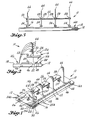
- Tooling 10 for a master model alignment uses a base 12, a pair of indexing bars 14a, and 14b, and a vertical alignment member 16.
- the top surface 18, of the base must be machined to close tolerance, and that surface leveled preferably to within .002 inches (0,05 mm) to form the base line plane for the tooling.
- Index bar 14a has vertical side 20, which is machined to a close tolerance, preferably of .002 inches (0,05 mm) to act as a buttock or reference.line and/or plane.
- the opposite side 22 is machined to the same tolerance and is parallel to side 20.
- This bar has a series of holes 24a, which are laid out along a line parallel to the buttock line.
- the second index bar 14b also has a series of holes 24b, set out along a line parallel to the buttock line. These holes are arranged to match the alignment of the holes in index bar 14a, and each pair of aligned holes in the two bars lie along a line that is perpendicular to the buttock line.
- the vertical alignment member 16 may use precision cubes, angles, or sine plates, acting as a pattern, but in this view an angle is used.
- the angle is shaped such that surface 26 extends vertically from the base plane and perpendicular to the buttock line with side 28 abutting side 22 of index bar 14a.
- a flat strip 30 is secured to the surface 26 of the vertical alignment member 16 and extends out along a line parallel to the surface of the base and as on extension of surface 26.
- a header or template station gage 32b has a support member 34, with an elongated slot 36, and a series of in line holes 38.
- the holes and the slot are all in line and are used in combination with pins 40a and 40b for quick securing of the gage to the indexed holes in the index bar 14b.
- An adjustable curved contact head 42 is located on the support member. That head can be adjusted with respect to the hole locations 38, to permit accurate measurement from the indexed hole locations on the index bar.
- a series of headers 44 are each individually contoured with respect to a part 46 of the header, located for contacting the base, and a part 48 of the header, located for contacting the side 20, of the index bar, representing the buttock line.
- the two index bars 14a and 14b are secured to surface 18 of the base 12 with the bars and the holes 24a and 24b of those bars aligned with respect to each other.
- a pair of header station gages 32a and 32b are placed on the index bars and the curved contact heads 42 adjusted to define an edge of a header location.
- a bar 50 extends between the two bars. That bar has parallel surfaces along opposite sides that are machine to close tolerances. The bar is held against the contact heads and used as a guide to scribe the header line 52, on the base. Each header location is scribed in this manner. Angle irons 54 are placed along the scribed lines and are then secured to the base.
- the headers 44 are then positioned against the angle iron with part 46 resting on the base and part 48 abutting against buttock line reference 20, and the header is then secured to the angle iron.
- the vertical alignment member 16 is then placed in position on the base and along the scribe line with side 28 abutting side 22 of the index bar 14a.
- the surface of the header is then brought up against flat strip 30 and the header is held in that position with rod 56 and nuts 58. This serves to align the headers vertically.
- Figures 7 and 8 show a different embodiment where an index bar 59, having an accurate side 60 to act as a buttock or reference line, is located on an accurately machined and leveled base 62, and the buttock line is located to contact an interior surface 64 of headers 66. These headers are each machined in reference to the surfaces 68 contacting the base, and the buttock referenced interior surface.
- An additional pair of index bars 70a and 70b are located on the base and alongside the headers. These additional bars each have a row of in-line indexing holes 72a and 72b which are aligned parallel to the buttock line, match each other and are aligned with matching pairs of holes extending perpendicular to the buttock line.
- the three indexing bars are aligned and secured to the base.
- a pair of header station gages 32 are used as before in conjunction with index bars 70a and 70b to scribe header locations on the base.
- Angle irons 74 are then located along the scribe lines, the headers 66 positioned to contact the angle irons, the base and the buttock line reference 60, and the headers secured to the angle iron.
- These headers may be vertically aligned as before, however, if the headers are long it is preferable to vertically align using an optical instrument 76.
- This optical instrument is preferably mounted on a structure 78, that has a track 80 that is leveled and that extends parallel to the buttock line as indicated by side 60 of index bar 59. This provides for moving the instrument to the position to sight in and set the vertical alignment and the headers are then secured in position with threaded bars 82 and nuts 84.
Landscapes
- Engineering & Computer Science (AREA)
- Mechanical Engineering (AREA)
- Automation & Control Theory (AREA)
- A Measuring Device Byusing Mechanical Method (AREA)
- Molds, Cores, And Manufacturing Methods Thereof (AREA)
- Length-Measuring Instruments Using Mechanical Means (AREA)
- Moulds For Moulding Plastics Or The Like (AREA)
Claims (5)
Applications Claiming Priority (1)
| Application Number | Priority Date | Filing Date | Title |
|---|---|---|---|
| PCT/US1983/000801 WO1984004720A1 (en) | 1983-05-23 | 1983-05-23 | Tooling for and method of fabricating master models |
Publications (2)
| Publication Number | Publication Date |
|---|---|
| EP0146541A1 EP0146541A1 (de) | 1985-07-03 |
| EP0146541B1 true EP0146541B1 (de) | 1988-09-21 |
Family
ID=22175179
Family Applications (1)
| Application Number | Title | Priority Date | Filing Date |
|---|---|---|---|
| EP83902075A Expired EP0146541B1 (de) | 1983-05-23 | 1983-05-23 | Einrichtung zum herstellen von hauptmodellen |
Country Status (4)
| Country | Link |
|---|---|
| US (1) | US4545102A (de) |
| EP (1) | EP0146541B1 (de) |
| DE (1) | DE3378027D1 (de) |
| WO (1) | WO1984004720A1 (de) |
Families Citing this family (5)
| Publication number | Priority date | Publication date | Assignee | Title |
|---|---|---|---|---|
| US5267143A (en) * | 1984-10-12 | 1993-11-30 | Sensor Adaptive Machines, Incorporated | Vision assisted fixture construction |
| IT1220339B (it) * | 1988-04-21 | 1990-06-15 | Marposs Spa | Calibro con una pluralita' di zone di riferimento,e relativo procedimento di fabbricazione |
| JP2004228084A (ja) | 2003-01-21 | 2004-08-12 | Samsung Sdi Co Ltd | 電界放出素子 |
| ES2388865B1 (es) * | 2010-12-23 | 2013-09-06 | Gamesa Innovation & Tech Sl | Molde de conchas partido para palas de aerogenerador, metodo de fabricacion de dicho molde y metodo de fabricacion de pala empleando dicho molde. |
| US11801619B2 (en) * | 2021-10-05 | 2023-10-31 | The Boeing Company | Rapid tooling layup mandrel |
Family Cites Families (15)
| Publication number | Priority date | Publication date | Assignee | Title |
|---|---|---|---|---|
| US1171818A (en) * | 1914-10-24 | 1916-02-15 | Builders Iron Foundry | Process of forming jigs or fixtures. |
| US1434651A (en) * | 1920-06-05 | 1922-11-07 | Haskelite Mfg Corp | Method of molding panels |
| US1904674A (en) * | 1932-02-29 | 1933-04-18 | Arramam B Rlumenthal | Combined graphic outline and work locating template for building models |
| US2274060A (en) * | 1938-10-31 | 1942-02-24 | United Shoe Machinery Corp | Mold and mold making method |
| US2238782A (en) * | 1938-12-24 | 1941-04-15 | Jean A Roche | Gauging device for complex curved surfaces |
| DE720003C (de) * | 1939-02-11 | 1942-04-22 | Henschel Flugzeugwerke Ag | Modell fuer die Anfertigung von Gesenken fuer die Blechverformung |
| US2652595A (en) * | 1950-01-24 | 1953-09-22 | Kish Plastic Products Inc | Method of making industrial models and fixtures |
| US2755510A (en) * | 1951-02-28 | 1956-07-24 | Smith Corp A O | Method of making profiling machine models |
| US2705375A (en) * | 1952-06-23 | 1955-04-05 | Northrop Aircraft Inc | Locating device |
| DE1022077B (de) * | 1954-08-07 | 1958-01-02 | Heyligenstaedt & Co | Steuereinrichtung fuer Nachformwerkzeugmaschinen, insbesondere Fraesmaschinen |
| US2887726A (en) * | 1956-04-24 | 1959-05-26 | Thomas D Vertin | Method of making plastic models |
| US3375568A (en) * | 1964-11-24 | 1968-04-02 | Data Resolved Tools Pty Ltd | Means and method for the construction of tools |
| GB1323396A (en) * | 1972-02-07 | 1973-07-11 | Blue Star Eng Ltd | Work-piece positioning structure |
| US3799721A (en) * | 1972-05-18 | 1974-03-26 | Int Fabric Molders Inc | Adjustable mold platen for fabric molding |
| FR2208760B3 (de) * | 1972-12-06 | 1976-01-09 | Alsthom Cgee Fr |
-
1983
- 1983-05-23 EP EP83902075A patent/EP0146541B1/de not_active Expired
- 1983-05-23 DE DE8383902075T patent/DE3378027D1/de not_active Expired
- 1983-05-23 WO PCT/US1983/000801 patent/WO1984004720A1/en not_active Ceased
- 1983-05-23 US US06/510,147 patent/US4545102A/en not_active Expired - Fee Related
Also Published As
| Publication number | Publication date |
|---|---|
| US4545102A (en) | 1985-10-08 |
| EP0146541A1 (de) | 1985-07-03 |
| DE3378027D1 (en) | 1988-10-27 |
| WO1984004720A1 (en) | 1984-12-06 |
Similar Documents
| Publication | Publication Date | Title |
|---|---|---|
| EP1225423B1 (de) | Verfahren zur Auswertung von Messfehlern in Koordinatenmessmaschinen und Messkörper für Koordinatenmessmaschinen | |
| US3990153A (en) | Automatic measurement of workpieces | |
| EP0146541B1 (de) | Einrichtung zum herstellen von hauptmodellen | |
| JPH06507721A (ja) | 位置確認装置 | |
| US2270158A (en) | Templet | |
| US4534200A (en) | Apparatus for mounting an automobile body on a checking frame | |
| JPH0296609A (ja) | V型溝の検査方法及び加工方法 | |
| JP2566922B2 (ja) | 基準部材を備えた装置 | |
| CN214055240U (zh) | 分中划线装置 | |
| CN210603072U (zh) | 锻件残余毛边的快速测量装置 | |
| CN115383405A (zh) | 一种多边形钢塔加工质量控制工艺 | |
| US3166853A (en) | Machinist's angle gauge and support | |
| CN109654970B (zh) | 一种焊装车身的精度调整及控制的有效测量装置 | |
| EP0337170A1 (de) | Vorrichtung zur Ermittlung des Mittelpunktes eines Steges | |
| JPS60217034A (ja) | ワイヤ放電加工機の基準装置 | |
| CN211178260U (zh) | 一种厚板坯连铸机内弧框架中心距的测量装置 | |
| US5421099A (en) | Inspection tool | |
| US2960776A (en) | Means for forming a profile template or the like | |
| US4626151A (en) | Tool alignment gauge | |
| RU2096741C1 (ru) | Способ размерного контроля крупногабаритного изделия и устройство для его осуществления | |
| US3841389A (en) | Curved roll-rack frame construction | |
| CN216757699U (zh) | 一种铜排折弯尺寸检测工装 | |
| JP2813908B2 (ja) | 治具の製作方法 | |
| CN223400272U (zh) | 一种多角度非垂直面位置度检测检具 | |
| CN221223601U (zh) | 一种尺子校对用基准平台 |
Legal Events
| Date | Code | Title | Description |
|---|---|---|---|
| PUAI | Public reference made under article 153(3) epc to a published international application that has entered the european phase |
Free format text: ORIGINAL CODE: 0009012 |
|
| 17P | Request for examination filed |
Effective date: 19841119 |
|
| AK | Designated contracting states |
Kind code of ref document: A1 Designated state(s): DE FR GB NL Designated state(s): DE FR GB NL |
|
| 17Q | First examination report despatched |
Effective date: 19860730 |
|
| GRAA | (expected) grant |
Free format text: ORIGINAL CODE: 0009210 |
|
| AK | Designated contracting states |
Kind code of ref document: B1 Designated state(s): DE FR GB NL |
|
| REF | Corresponds to: |
Ref document number: 3378027 Country of ref document: DE Date of ref document: 19881027 |
|
| ET | Fr: translation filed | ||
| PLBE | No opposition filed within time limit |
Free format text: ORIGINAL CODE: 0009261 |
|
| STAA | Information on the status of an ep patent application or granted ep patent |
Free format text: STATUS: NO OPPOSITION FILED WITHIN TIME LIMIT |
|
| 26N | No opposition filed | ||
| PGFP | Annual fee paid to national office [announced via postgrant information from national office to epo] |
Ref country code: GB Payment date: 19900501 Year of fee payment: 8 |
|
| PGFP | Annual fee paid to national office [announced via postgrant information from national office to epo] |
Ref country code: NL Payment date: 19900531 Year of fee payment: 8 Ref country code: FR Payment date: 19900531 Year of fee payment: 8 Ref country code: DE Payment date: 19900531 Year of fee payment: 8 |
|
| PG25 | Lapsed in a contracting state [announced via postgrant information from national office to epo] |
Ref country code: GB Effective date: 19910523 |
|
| PG25 | Lapsed in a contracting state [announced via postgrant information from national office to epo] |
Ref country code: NL Effective date: 19911201 |
|
| NLV4 | Nl: lapsed or anulled due to non-payment of the annual fee | ||
| GBPC | Gb: european patent ceased through non-payment of renewal fee | ||
| PG25 | Lapsed in a contracting state [announced via postgrant information from national office to epo] |
Ref country code: FR Effective date: 19920131 |
|
| PG25 | Lapsed in a contracting state [announced via postgrant information from national office to epo] |
Ref country code: DE Effective date: 19920303 |
|
| REG | Reference to a national code |
Ref country code: FR Ref legal event code: ST |