EP0146597B1 - Installation pour l'ozonation d'un fluide - Google Patents
Installation pour l'ozonation d'un fluide Download PDFInfo
- Publication number
- EP0146597B1 EP0146597B1 EP84902329A EP84902329A EP0146597B1 EP 0146597 B1 EP0146597 B1 EP 0146597B1 EP 84902329 A EP84902329 A EP 84902329A EP 84902329 A EP84902329 A EP 84902329A EP 0146597 B1 EP0146597 B1 EP 0146597B1
- Authority
- EP
- European Patent Office
- Prior art keywords
- fluid
- gas
- flow channel
- region
- ozoniser
- Prior art date
- Legal status (The legal status is an assumption and is not a legal conclusion. Google has not performed a legal analysis and makes no representation as to the accuracy of the status listed.)
- Expired
Links
- 239000012530 fluid Substances 0.000 title claims abstract description 40
- 238000006385 ozonation reaction Methods 0.000 title description 3
- CBENFWSGALASAD-UHFFFAOYSA-N Ozone Chemical compound [O-][O+]=O CBENFWSGALASAD-UHFFFAOYSA-N 0.000 claims abstract description 28
- 238000005191 phase separation Methods 0.000 claims abstract description 4
- 239000007789 gas Substances 0.000 claims description 36
- 239000001301 oxygen Substances 0.000 claims description 4
- 229910052760 oxygen Inorganic materials 0.000 claims description 4
- QVGXLLKOCUKJST-UHFFFAOYSA-N atomic oxygen Chemical compound [O] QVGXLLKOCUKJST-UHFFFAOYSA-N 0.000 claims description 3
- 230000037431 insertion Effects 0.000 claims 4
- 238000003780 insertion Methods 0.000 claims 4
- 238000011144 upstream manufacturing Methods 0.000 claims 2
- 239000002826 coolant Substances 0.000 claims 1
- 239000000203 mixture Substances 0.000 abstract description 11
- XLYOFNOQVPJJNP-UHFFFAOYSA-N water Substances O XLYOFNOQVPJJNP-UHFFFAOYSA-N 0.000 abstract description 8
- 238000002156 mixing Methods 0.000 description 8
- 239000007788 liquid Substances 0.000 description 5
- 230000005514 two-phase flow Effects 0.000 description 4
- 238000001816 cooling Methods 0.000 description 3
- 230000002349 favourable effect Effects 0.000 description 3
- 230000003068 static effect Effects 0.000 description 3
- VYPSYNLAJGMNEJ-UHFFFAOYSA-N Silicium dioxide Chemical compound O=[Si]=O VYPSYNLAJGMNEJ-UHFFFAOYSA-N 0.000 description 2
- 230000015572 biosynthetic process Effects 0.000 description 2
- 238000006243 chemical reaction Methods 0.000 description 2
- 238000004519 manufacturing process Methods 0.000 description 2
- 239000007800 oxidant agent Substances 0.000 description 2
- 239000000741 silica gel Substances 0.000 description 2
- 229910002027 silica gel Inorganic materials 0.000 description 2
- MYMOFIZGZYHOMD-UHFFFAOYSA-N Dioxygen Chemical compound O=O MYMOFIZGZYHOMD-UHFFFAOYSA-N 0.000 description 1
- 238000003287 bathing Methods 0.000 description 1
- 238000009833 condensation Methods 0.000 description 1
- 230000005494 condensation Effects 0.000 description 1
- 230000008878 coupling Effects 0.000 description 1
- 238000010168 coupling process Methods 0.000 description 1
- 238000005859 coupling reaction Methods 0.000 description 1
- 238000000354 decomposition reaction Methods 0.000 description 1
- 239000002270 dispersing agent Substances 0.000 description 1
- 230000035622 drinking Effects 0.000 description 1
- 238000001035 drying Methods 0.000 description 1
- 239000000428 dust Substances 0.000 description 1
- 239000000839 emulsion Substances 0.000 description 1
- 238000000034 method Methods 0.000 description 1
- 238000012806 monitoring device Methods 0.000 description 1
- 210000000056 organ Anatomy 0.000 description 1
- 230000008929 regeneration Effects 0.000 description 1
- 238000011069 regeneration method Methods 0.000 description 1
- 210000002023 somite Anatomy 0.000 description 1
- 239000000126 substance Substances 0.000 description 1
- 239000000725 suspension Substances 0.000 description 1
Images
Classifications
-
- C—CHEMISTRY; METALLURGY
- C02—TREATMENT OF WATER, WASTE WATER, SEWAGE, OR SLUDGE
- C02F—TREATMENT OF WATER, WASTE WATER, SEWAGE, OR SLUDGE
- C02F1/00—Treatment of water, waste water, or sewage
- C02F1/72—Treatment of water, waste water, or sewage by oxidation
- C02F1/78—Treatment of water, waste water, or sewage by oxidation with ozone
-
- C—CHEMISTRY; METALLURGY
- C01—INORGANIC CHEMISTRY
- C01B—NON-METALLIC ELEMENTS; COMPOUNDS THEREOF; METALLOIDS OR COMPOUNDS THEREOF NOT COVERED BY SUBCLASS C01C
- C01B13/00—Oxygen; Ozone; Oxides or hydroxides in general
- C01B13/10—Preparation of ozone
- C01B13/11—Preparation of ozone by electric discharge
-
- C—CHEMISTRY; METALLURGY
- C01—INORGANIC CHEMISTRY
- C01B—NON-METALLIC ELEMENTS; COMPOUNDS THEREOF; METALLOIDS OR COMPOUNDS THEREOF NOT COVERED BY SUBCLASS C01C
- C01B2201/00—Preparation of ozone by electrical discharge
- C01B2201/10—Dischargers used for production of ozone
- C01B2201/14—Concentric/tubular dischargers
-
- C—CHEMISTRY; METALLURGY
- C01—INORGANIC CHEMISTRY
- C01B—NON-METALLIC ELEMENTS; COMPOUNDS THEREOF; METALLOIDS OR COMPOUNDS THEREOF NOT COVERED BY SUBCLASS C01C
- C01B2201/00—Preparation of ozone by electrical discharge
- C01B2201/60—Feed streams for electrical dischargers
-
- C—CHEMISTRY; METALLURGY
- C01—INORGANIC CHEMISTRY
- C01B—NON-METALLIC ELEMENTS; COMPOUNDS THEREOF; METALLOIDS OR COMPOUNDS THEREOF NOT COVERED BY SUBCLASS C01C
- C01B2201/00—Preparation of ozone by electrical discharge
- C01B2201/70—Cooling of the discharger; Means for making cooling unnecessary
- C01B2201/74—Cooling of the discharger; Means for making cooling unnecessary by liquid
- C01B2201/76—Water
-
- C—CHEMISTRY; METALLURGY
- C02—TREATMENT OF WATER, WASTE WATER, SEWAGE, OR SLUDGE
- C02F—TREATMENT OF WATER, WASTE WATER, SEWAGE, OR SLUDGE
- C02F2201/00—Apparatus for treatment of water, waste water or sewage
- C02F2201/78—Details relating to ozone treatment devices
- C02F2201/782—Ozone generators
Definitions
- the present invention relates to a device according to the preamble of claim 1.
- a fluid is understood to mean a pure liquid, a liquid mixture or a multi-phase mixture with a liquid as a continuous phase (for example a suspension or emulsion).
- Ozone is one of the strongest oxidizing agents. It is used in particular for the treatment of drinking, industrial and bathing water as well as in the chemical industry.
- ozone generating devices are known today, the basic structure of which is largely identical. They usually have a gas processing unit in the form of one or more dryers, an ozonator and a mixing system for introducing the ozone into the fluid. The elements mentioned are usually spatially separated and are only coupled to one another by a pipe system.
- the spatially separated gas introduction element is often at a structurally favorable d. H. easily accessible point built into the fluid line. However, this does not guarantee that a two-phase flow form that is favorable for the gas-liquid mass transfer is created in the line.
- the British patent specification GB-A-1 117 from 1910 shows an ozonization device which has no means for influencing the two-phase flow flowing in the central tube.
- the entire central tube would have to be replaced. Since this central tube also serves as the inner electrode of the ozone formation area, either the outer electrode or the high-voltage supply would also have to be replaced due to the change in the discharge gap geometry. Since there are no means for optimizing the ozone input in the smooth central tube, an additional mixing and contacting device is connected downstream.
- German patent application DE-A-1 5-17 541 describes a method in which the water to be ozonized probably cools the ozonator, but not the air to be ozonized in order to reduce the moisture content thereof.
- the ozone-containing gas is injected into the water to be ozonized, but is no longer additionally dispersed into the water, so that a relatively large amount of ozone-containing gas escapes into the atmosphere in the downstream expansion tank.
- the present invention is based on the object of proposing a device for ozonizing a fluid in which the ozone-containing gas is introduced into the fluid as effectively as possible.
- it is intended to ensure the highest possible ozone input into the fluid, regardless of the fluid connection lines or the flow parameters prevailing therein.
- the two-phase mixture of ozone-containing gas and fluid formed in the gas inlet element flows out of the gas inlet element into the second region of the ozonator. Thanks to the exchangeable inserts, it is exposed to controlled flow conditions within the second area of the ozonator. Because of the known close relations between flow and mass transfer in two-phase mixtures, this also controls the mass transfer (ozone input into the fluid).
- the two-phase flow parameters can be varied within wide limits by dimensioning the interchangeable insert pieces arranged in the second area, without having to make any changes in the feed and discharge system.
- the ozonator and the gas inlet element form a structural unit that can also be integrated into existing pipe systems with little effort.
- phase separating element e.g. B. to arrange a cyclone, a pipe bend or a separating boiler.
- This measure results in a compact device which does not load the fluid line system with gas, which is particularly advantageous in the case of downstream centrifugal pumps.
- an intermediate piece equipped with or without additional dispersing agents between the ozonator and the phase separation element it is also possible to arrange an intermediate piece equipped with or without additional dispersing agents between the ozonator and the phase separation element.
- the gas pretreated in this way can be placed in a dryer downstream of the heat exchanger, e.g. B. in a column dryer filled with silica gel or on a cooled surface (z. B. Peltier element).
- the gas treated in this way is then preferably introduced into the first area of the ozonator via a throughput monitoring device and a moisture meter.
- a mixer designed in the form of a Venturi nozzle is expediently used as the gas introduction element.
- Such elements are known. Due to the negative pressure generated by the flowing fluid in the Venturi nozzle, the gas to be ozonized is drawn through the dryer and ozonator without additional conveying elements.
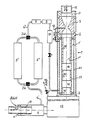
- the ozonator 1 has a flow channel 1 ′′ through which the fluid can flow and which is formed by a tube 23.
- a gas introduction element 3 similar to a venturi nozzle is arranged on the fluid inlet side of the tube 23.
- this tube 23 is connected to a phase separating element 13 designed as a cyclone.
- the tubes 22 and 23 and the gas introduction element or phase separation element are expediently connected to one another via coupling and / or intermediate pieces 2.
- Two static mixing elements 16 are arranged in the flow channel 1 ′′.
- the insert pieces 20 in the form of sleeves, the flow cross-section can be adjusted in the second region 1 ′′ with regard to favorable flow conditions.
- These sleeves 20 also serve as support elements for the static mixing elements and are designed as replacement parts.
- the tubular outer housing 21 serves as a protection against accidental contact and at the same time increases the mechanical strength of the combination of the gas inlet organ and ozonator. In order not to unnecessarily burden the figure, the power supply lines to the first area 1 'of the ozonator are omitted.
- the gas to be ozonized here air
- the heat exchanger is designed as a double-tube exchanger, whereby the ozonized fluid flows in the central tube and cools the air flowing in the annular gap.
- the outer tube also serves as a cooling surface, it is connected to the inner tube via support plates 18. During cooling, water vapor condenses from the air to the dew point corresponding to the fluid temperature. The condensate then flows out of the heat exchanger in the direction of arrow A.
- the air thus pre-dried flows via line 4 'and a changeover valve 3 W into one of the two silica gel-filled dryer columns 5' or 5 ".
- dryer columns are regenerated in push-pull. This ensures constant ozone production. However, it is also possible to use only one dryer column, the ozone production being interrupted during its regeneration.
- the dried air then flows through a second valve 3W and through line 4 "via a moisture meter 8, a pressure measuring station 9 and a flow monitor 10 (for example in the form of a rotameter) into the first area 1 'of the ozonator.
- the oxygen in the ozonator is ozonized by means of an electrical spark discharge, and the ozone-containing gas thus formed is sucked in by the Venturi nozzle via a connecting line 12.
- a shut-off valve 11 arranged, which is actuated by means of the signals from the moisture meter 8, the pressure measuring station 9 and the flow monitor 10 when the permissible values are exceeded. This measure prevents the fluid from flowing into the first region 1 '.
- a one-way valve 11 ' can also be used.
- Such a device for ozonization can be installed in existing fluid lines with little effort.
- suitable sleeves 20 and optionally additional redispersion elements 16 are used in the fluid flow channel 1 ′′.
Landscapes
- Chemical & Material Sciences (AREA)
- Organic Chemistry (AREA)
- Life Sciences & Earth Sciences (AREA)
- Hydrology & Water Resources (AREA)
- Engineering & Computer Science (AREA)
- Environmental & Geological Engineering (AREA)
- Water Supply & Treatment (AREA)
- Inorganic Chemistry (AREA)
- Oxygen, Ozone, And Oxides In General (AREA)
- Treatment Of Water By Oxidation Or Reduction (AREA)
Abstract
Claims (5)
Priority Applications (1)
| Application Number | Priority Date | Filing Date | Title |
|---|---|---|---|
| AT84902329T ATE27443T1 (de) | 1983-06-20 | 1984-06-15 | Vorrichtung zum ozonisieren eines fluids. |
Applications Claiming Priority (2)
| Application Number | Priority Date | Filing Date | Title |
|---|---|---|---|
| CH335283 | 1983-06-20 | ||
| CH3352/83 | 1983-06-20 |
Publications (2)
| Publication Number | Publication Date |
|---|---|
| EP0146597A1 EP0146597A1 (fr) | 1985-07-03 |
| EP0146597B1 true EP0146597B1 (fr) | 1987-05-27 |
Family
ID=4254118
Family Applications (1)
| Application Number | Title | Priority Date | Filing Date |
|---|---|---|---|
| EP84902329A Expired EP0146597B1 (fr) | 1983-06-20 | 1984-06-15 | Installation pour l'ozonation d'un fluide |
Country Status (5)
| Country | Link |
|---|---|
| US (1) | US4686036A (fr) |
| EP (1) | EP0146597B1 (fr) |
| AU (1) | AU561763B2 (fr) |
| DE (1) | DE3463923D1 (fr) |
| WO (1) | WO1985000161A1 (fr) |
Families Citing this family (8)
| Publication number | Priority date | Publication date | Assignee | Title |
|---|---|---|---|---|
| JPH0433998Y2 (fr) * | 1987-10-29 | 1992-08-13 | ||
| RU2162061C2 (ru) * | 1998-12-23 | 2001-01-20 | Курников Александр Серафимович | Установка для озонирования воды |
| FR2814736B1 (fr) * | 2000-09-26 | 2003-03-21 | Tarng Liou Huei | Tube de formation d'ozone refroidi par air et dispositif de production d'ozone base sur la dynamique des fluides comportant un tel tube |
| US6534023B1 (en) * | 2000-09-26 | 2003-03-18 | Huei Tarng Liou | Fluid dynamic ozone generating assembly |
| US8735337B2 (en) * | 2007-03-13 | 2014-05-27 | Food Safety Technology, Llc | Aqueous ozone solution for ozone cleaning system |
| US9068149B2 (en) * | 2007-03-14 | 2015-06-30 | Food Safety Technology, Llc | Ozone cleaning system |
| US9522348B2 (en) | 2008-07-24 | 2016-12-20 | Food Safety Technology, Llc | Ozonated liquid dispensing unit |
| US9174845B2 (en) | 2008-07-24 | 2015-11-03 | Food Safety Technology, Llc | Ozonated liquid dispensing unit |
Family Cites Families (10)
| Publication number | Priority date | Publication date | Assignee | Title |
|---|---|---|---|---|
| GB191001117A (en) * | 1910-01-15 | 1910-10-20 | Casimir Stanislas Piestrak | Improvements in and relating to Apparatus for the Sterilization of Water or any other Liquid by Means of Ozonisation. |
| FR1088579A (fr) * | 1953-07-16 | 1955-03-08 | Cie Des Eaux Et De L Ozone | Perfectionnements aux dispositifs pour l'ozonisation des liquides tels que de l'eau |
| CH318835A (de) * | 1953-09-07 | 1957-01-31 | Rheno Ag | Einrichtung zum Entkeimen von Wasser |
| DE1517541A1 (de) * | 1966-11-02 | 1970-09-17 | Inst Schiffbau | Verfahren zum Ozonisieren von Wasser |
| DE2225984A1 (de) * | 1972-05-09 | 1973-12-20 | Wiest Fa Richard | Verfahren zum entkeimen von fluessigkeiten |
| US4090960A (en) * | 1974-05-08 | 1978-05-23 | Dynalytics Corporation | Gas energizing apparatus and related method |
| CA1048733A (fr) * | 1977-02-02 | 1979-02-20 | Ontario Research Foundation | Epurateur a l'ozone et a l'ultraviolet pour l'eau |
| DE2827151C2 (de) * | 1978-06-21 | 1982-05-06 | Messer Griesheim Gmbh, 6000 Frankfurt | Verfahren zur Wasserbehandlung mittels Ozon |
| US4273660A (en) * | 1979-02-21 | 1981-06-16 | Beitzel Stuart W | Purification of water through the use of ozone and ultraviolet light |
| US4274970A (en) * | 1979-10-29 | 1981-06-23 | Beitzel Stuart W | Method and apparatus for treating water |
-
1984
- 1984-06-15 EP EP84902329A patent/EP0146597B1/fr not_active Expired
- 1984-06-15 AU AU30156/84A patent/AU561763B2/en not_active Ceased
- 1984-06-15 DE DE8484902329T patent/DE3463923D1/de not_active Expired
- 1984-06-15 WO PCT/CH1984/000097 patent/WO1985000161A1/fr not_active Ceased
-
1986
- 1986-02-12 US US06/828,695 patent/US4686036A/en not_active Expired - Fee Related
Also Published As
| Publication number | Publication date |
|---|---|
| DE3463923D1 (en) | 1987-07-02 |
| EP0146597A1 (fr) | 1985-07-03 |
| US4686036A (en) | 1987-08-11 |
| AU3015684A (en) | 1985-01-25 |
| WO1985000161A1 (fr) | 1985-01-17 |
| AU561763B2 (en) | 1987-05-14 |
Similar Documents
| Publication | Publication Date | Title |
|---|---|---|
| DE68909052T2 (de) | Oxydationskammer. | |
| DE102018127371B4 (de) | Vorrichtung und Verfahren zur Nassreinigung eines Gasstromes | |
| DE3927701A1 (de) | Verfahren und anlage zur reinigung eines gases mit festen und gasfoermigen beimengungen | |
| DE2534033A1 (de) | Hochfrequenzroehrenozonisator | |
| US4112025A (en) | Method of and apparatus for jet aeration | |
| DE4110687C2 (de) | Vorrichtung in Modulbauweise zum Behandeln schadstoffbelasteter wäßriger Flüssigkeiten | |
| DE10049337B4 (de) | Strömungsdynamischer ozonerzeugender Aufbau | |
| EP0146597A1 (fr) | Installation pour l'ozonation d'un fluide. | |
| DE2104525A1 (de) | Kaltabscheider | |
| DE2534032B2 (de) | Hochfrequenzozonisator | |
| EP0446436B1 (fr) | Procédé et dispositif pour la combustion d'impuretés dans un courant de milieu | |
| DE4200802A1 (de) | Vorrichtung zur reinigung von abwasser | |
| DE3920321C2 (fr) | ||
| EP0082809B1 (fr) | Procédé et appareil pour la séparation continue de matiéres suspendues d'un liquide pollué | |
| DE3900731A1 (de) | Vorrichtung zur abwasser-reinigung durch flockung und flotation | |
| DE3738473A1 (de) | Statikmischer | |
| US2203592A (en) | Gas scrubber | |
| AT387158B (de) | Vorrichtung zur reinigung von abgasen | |
| DE854200C (de) | Vorrichtung zum Abscheiden von festen und fluessigen Beimengungen aus Luft, Gasen und Daempfen | |
| AT505752B1 (de) | Vorrichtung zum verandern des venturikehlenquerschnitts eines venturisystems | |
| DE102018218369B4 (de) | Gaslösesystem mit Doppelmischern | |
| DE3313544A1 (de) | Reaktor fuer die entschweflung von rauchgasen | |
| DE3600484A1 (de) | Ozonisierungsvorrichtung | |
| SU1114629A1 (ru) | Устройство дл магнитной обработки жидкости | |
| DE1501480B2 (fr) |
Legal Events
| Date | Code | Title | Description |
|---|---|---|---|
| PUAI | Public reference made under article 153(3) epc to a published international application that has entered the european phase |
Free format text: ORIGINAL CODE: 0009012 |
|
| 17P | Request for examination filed |
Effective date: 19850221 |
|
| AK | Designated contracting states |
Designated state(s): AT BE DE FR GB LU NL SE |
|
| 17Q | First examination report despatched |
Effective date: 19860314 |
|
| GRAA | (expected) grant |
Free format text: ORIGINAL CODE: 0009210 |
|
| AK | Designated contracting states |
Kind code of ref document: B1 Designated state(s): AT BE DE FR GB LU NL SE |
|
| REF | Corresponds to: |
Ref document number: 27443 Country of ref document: AT Date of ref document: 19870615 Kind code of ref document: T |
|
| PG25 | Lapsed in a contracting state [announced via postgrant information from national office to epo] |
Ref country code: LU Free format text: LAPSE BECAUSE OF NON-PAYMENT OF DUE FEES Effective date: 19870630 |
|
| PGFP | Annual fee paid to national office [announced via postgrant information from national office to epo] |
Ref country code: NL Payment date: 19870630 Year of fee payment: 4 |
|
| REF | Corresponds to: |
Ref document number: 3463923 Country of ref document: DE Date of ref document: 19870702 |
|
| ET | Fr: translation filed | ||
| PLBE | No opposition filed within time limit |
Free format text: ORIGINAL CODE: 0009261 |
|
| STAA | Information on the status of an ep patent application or granted ep patent |
Free format text: STATUS: NO OPPOSITION FILED WITHIN TIME LIMIT |
|
| 26N | No opposition filed | ||
| PG25 | Lapsed in a contracting state [announced via postgrant information from national office to epo] |
Ref country code: NL Effective date: 19890101 |
|
| NLV4 | Nl: lapsed or anulled due to non-payment of the annual fee | ||
| PG25 | Lapsed in a contracting state [announced via postgrant information from national office to epo] |
Ref country code: GB Effective date: 19890615 Ref country code: AT Effective date: 19890615 |
|
| PG25 | Lapsed in a contracting state [announced via postgrant information from national office to epo] |
Ref country code: SE Effective date: 19890616 |
|
| PG25 | Lapsed in a contracting state [announced via postgrant information from national office to epo] |
Ref country code: BE Effective date: 19890630 |
|
| BERE | Be: lapsed |
Owner name: LAEDERACH- ZAUGG BARBARA Effective date: 19890630 |
|
| GBPC | Gb: european patent ceased through non-payment of renewal fee | ||
| PG25 | Lapsed in a contracting state [announced via postgrant information from national office to epo] |
Ref country code: FR Free format text: LAPSE BECAUSE OF NON-PAYMENT OF DUE FEES Effective date: 19900228 |
|
| PG25 | Lapsed in a contracting state [announced via postgrant information from national office to epo] |
Ref country code: DE Effective date: 19900301 |
|
| REG | Reference to a national code |
Ref country code: FR Ref legal event code: ST |
|
| EUG | Se: european patent has lapsed |
Ref document number: 84902329.6 Effective date: 19900418 |