EP0146650A2 - Magasin pour outils remplaçables et procédé pour positionner des outils au moyen du magasin - Google Patents
Magasin pour outils remplaçables et procédé pour positionner des outils au moyen du magasin Download PDFInfo
- Publication number
- EP0146650A2 EP0146650A2 EP83112990A EP83112990A EP0146650A2 EP 0146650 A2 EP0146650 A2 EP 0146650A2 EP 83112990 A EP83112990 A EP 83112990A EP 83112990 A EP83112990 A EP 83112990A EP 0146650 A2 EP0146650 A2 EP 0146650A2
- Authority
- EP
- European Patent Office
- Prior art keywords
- magazine
- tool
- spindle
- units
- tools
- Prior art date
- Legal status (The legal status is an assumption and is not a legal conclusion. Google has not performed a legal analysis and makes no representation as to the accuracy of the status listed.)
- Granted
Links
- 238000000034 method Methods 0.000 title claims description 20
- 230000007246 mechanism Effects 0.000 claims abstract description 70
- 210000000078 claw Anatomy 0.000 claims description 38
- 230000002093 peripheral effect Effects 0.000 claims description 4
- 238000003780 insertion Methods 0.000 claims description 2
- 230000037431 insertion Effects 0.000 claims description 2
- 230000000994 depressogenic effect Effects 0.000 claims 1
- 238000003754 machining Methods 0.000 abstract description 2
- 230000006835 compression Effects 0.000 description 5
- 238000007906 compression Methods 0.000 description 5
- 230000005540 biological transmission Effects 0.000 description 1
- 238000006073 displacement reaction Methods 0.000 description 1
- 230000000694 effects Effects 0.000 description 1
Images
Classifications
-
- B—PERFORMING OPERATIONS; TRANSPORTING
- B23—MACHINE TOOLS; METAL-WORKING NOT OTHERWISE PROVIDED FOR
- B23Q—DETAILS, COMPONENTS, OR ACCESSORIES FOR MACHINE TOOLS, e.g. ARRANGEMENTS FOR COPYING OR CONTROLLING; MACHINE TOOLS IN GENERAL CHARACTERISED BY THE CONSTRUCTION OF PARTICULAR DETAILS OR COMPONENTS; COMBINATIONS OR ASSOCIATIONS OF METAL-WORKING MACHINES, NOT DIRECTED TO A PARTICULAR RESULT
- B23Q3/00—Devices holding, supporting, or positioning work or tools, of a kind normally removable from the machine
- B23Q3/155—Arrangements for automatic insertion or removal of tools, e.g. combined with manual handling
- B23Q3/1552—Arrangements for automatic insertion or removal of tools, e.g. combined with manual handling parts of devices for automatically inserting or removing tools
- B23Q3/15526—Storage devices; Drive mechanisms therefor
-
- B—PERFORMING OPERATIONS; TRANSPORTING
- B23—MACHINE TOOLS; METAL-WORKING NOT OTHERWISE PROVIDED FOR
- B23Q—DETAILS, COMPONENTS, OR ACCESSORIES FOR MACHINE TOOLS, e.g. ARRANGEMENTS FOR COPYING OR CONTROLLING; MACHINE TOOLS IN GENERAL CHARACTERISED BY THE CONSTRUCTION OF PARTICULAR DETAILS OR COMPONENTS; COMBINATIONS OR ASSOCIATIONS OF METAL-WORKING MACHINES, NOT DIRECTED TO A PARTICULAR RESULT
- B23Q3/00—Devices holding, supporting, or positioning work or tools, of a kind normally removable from the machine
- B23Q3/155—Arrangements for automatic insertion or removal of tools, e.g. combined with manual handling
- B23Q3/1552—Arrangements for automatic insertion or removal of tools, e.g. combined with manual handling parts of devices for automatically inserting or removing tools
- B23Q3/15526—Storage devices; Drive mechanisms therefor
- B23Q2003/15527—Storage devices; Drive mechanisms therefor the storage device including means to latch tools
-
- Y—GENERAL TAGGING OF NEW TECHNOLOGICAL DEVELOPMENTS; GENERAL TAGGING OF CROSS-SECTIONAL TECHNOLOGIES SPANNING OVER SEVERAL SECTIONS OF THE IPC; TECHNICAL SUBJECTS COVERED BY FORMER USPC CROSS-REFERENCE ART COLLECTIONS [XRACs] AND DIGESTS
- Y10—TECHNICAL SUBJECTS COVERED BY FORMER USPC
- Y10T—TECHNICAL SUBJECTS COVERED BY FORMER US CLASSIFICATION
- Y10T483/00—Tool changing
- Y10T483/17—Tool changing including machine tool or component
- Y10T483/1733—Rotary spindle machine tool [e.g., milling machine, boring, machine, grinding machine, etc.]
- Y10T483/179—Direct tool exchange between spindle and matrix
-
- Y—GENERAL TAGGING OF NEW TECHNOLOGICAL DEVELOPMENTS; GENERAL TAGGING OF CROSS-SECTIONAL TECHNOLOGIES SPANNING OVER SEVERAL SECTIONS OF THE IPC; TECHNICAL SUBJECTS COVERED BY FORMER USPC CROSS-REFERENCE ART COLLECTIONS [XRACs] AND DIGESTS
- Y10—TECHNICAL SUBJECTS COVERED BY FORMER USPC
- Y10T—TECHNICAL SUBJECTS COVERED BY FORMER US CLASSIFICATION
- Y10T483/00—Tool changing
- Y10T483/18—Tool transfer to or from matrix
- Y10T483/1809—Matrix including means to latch tool
Definitions
- the present invention relates to a magazine for replaceable tools used in an automatic machine tool.
- the present invention further relates to a tool indexing method for positioning a tool mounted in the magazine into a predetermined position conveying the tool into the front of a machine tool.
- FMS flexible machining system
- the method (a) has the disadvantage that the availability of the machine tool is reduced because of the necessity to stop the machine for tool replacement. It is also disadvantageous in that it is impossible to have the system operate unattended because of the necessity for manual intervention during tool changing. Generally, the machine operates using both tools commonly used for various operations and tools used exclusively for particular operations. Therefore, the method (b) is disadvantageous in that, when these tools are received in one tool magazine, it is necessary to have the commonly used tools in every tool magazine thus making this method uneconomical because of an increase,in numbers of tools.
- the method (c) is also disadvantageous in that it requires various means such as means for conveying and indexing the submagazine and means for loading a tool into the tool magazine mounted on the machine tool, resulting in increased cost and in the requirement for greater space, as with the case of method (b).
- An object of the present invention is to provide an improved magazine for replaceable tools.
- the magazine includes a frame mounted on a tool pallet, and a pair of magazine units each comprising a supporter and a plurality of tool holding mechanisms supported on the outer peripheral portion of the supporter.
- the pair of magazine units are rotatably supported about a center shaft extending in the frame.
- the magazine units confront with each other with a predetermined distance therebetween in axial direction of the center shaft.
- the respective tool holding mechanism of one of the magazine units is offset by half a pitch in phase relative to respective tool holding mechanisms of the other magazine unit.
- Each of the tool holding mechanism holds the tool in such ⁇ a manner that longitudinal axis of the tool extends in parallel with the axial direction of the center shaft.
- each of the tool holding mechanisms permits the tool to be inserted thereinto or released therefrom in a direction perpendicular to the axis of the center shaft.
- positioning mechanism is provided which is disposed between the magazine unit and the frame in order to position each of the tool holding mechanisms of each of the magazine units into a predetermined index position.
- Another object of the present invention is to provide an operation method for indexing tools using the magazine.
- tools are exchanged between a tool magazine mounted on a machine tool and a separately provided replaceable tool magazine.
- a tool is held by one of the tool holding mechanisms of the magazine and conveyed to the front of the machine tool.
- the tool is indexed into a predetermined position by moving the tool magazine by means of the actuation of a spindle of the machine tool, so that tools are indexed into predetermined positions, rapidly and accurately, without requiring any .
- special tool indexing means to thereby solve problems of conventional machines.
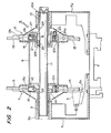
- the pair of magazine units 7 and 8 are urged to move to the right in Fi g . 2 by a compression spring 22 provided between the supporter 12 and the guide ring 14 of the magazine unit 7 (one of the pair of magazine units at the left side in Fig. 2) so that fixed pins 23 formed on the ring 12A fixed on the supporter 12 of the magazine unit 8 (the other magazine unit at the right side in Fig. 2) are caused to enter fixed holes 24a equidistantly formed in an intervention member 24 fixed to the boss 10a of the bearing 10 and the guide ring 15 in the same number (sixteen in the illustrated embodiment) as that of the tool holding mechanisms 13 of the pair of magazine units 7 and 8 to thereby prevent the pair of magazine units 7 and 8 from freely rotating around the center shaft 11.
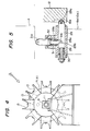
- the pair of magazine units 7 and 8 are supported on the center shaft 11 such that the respective phases of the total holding mechanisms of the respective magazine units 7 and 8 are shifted by a half pitch from each other as shown in Fig. 4.
- the above-mentioned fixed pins 23 and the fixed holes 24a are arranged such that the pair of magazine units 7 and 8 can be fixed to the frame F2 at every half pitch so as to constitute a positioning mechanism for positioning the respective tool holding mechanisms 13 of the respective magazine units 7 and 8 into predetermined index positions (the central upper end position of each of the magazine units 7 and 8 in this embodiment).
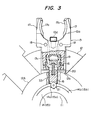
- Each of the tool holding mechanisms 13 are attached to the outer periphery of the supporter 12 such that the top ends of the respective claws through or out-of which the tool 3 is to be inserted/removed are disposed outward and the pivotal plane in which the respective claws are pivoted about the pivotal axes 18 (the plane perpendicular to the plane of paper in Fig. 2) is made parallel with the supporter 12.
- a housing 12B is fixedly attached to the one supporter 12 (for the magazine unit 8) which is fixed to the center shaft 11 by the stopped ring 25 which is in turn fittingly attached to the housing unit 12B.
- a slip key 26 is fixed to the ring 12A and the tip end of the slip key 26 is inserted into a key slot 27 to prevent the circumferential rotation of the lock member 16.
- the outer end surface of the supporter 12 is in contact with the guide ring 15 to thereby prevent excessive movement of the magazine units 7 and 8 in the rightward direction in Fig. 2.
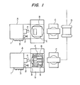
- a tool 3 from a tool station is held in a predetermined one of the tool holding mechanisms 13 of the magazine 5 mounted on the tool pallet F.
- the tool pallet number replaceable tools magazine number
- the tool number in the magazine 5 and the tool code (a unique code is allotted to each tool) are stored in a computer for controlling the machine tool.
- the tool pallet F is placed in its stand-by state at a pallet storage location until a replacement command is issued from the computer,
- the tool pallet F on which the magazine 5 is mounted is put on the remotely controlled truck D, conveyed to the automatic pallet changer C of a machine tool A, and pulled into the automatic pallet changer C together with the magazine 5.
- the tool pallet F is placed on standby in the automatic pallet changer C.
- the tool pallet F is moved onto the rotary table B of the machine tool A and arranged such that the magazine unit 7 side is directed to the spindle 4 and at the same time the center of the magazine 5 is in registration with the Y-axis of the machine tool controlling axes (the plane in which the spindle undergoes vertical move-Tent). Simultaneously with the above-mentioned operation, a tool 3 which has thus far been held by the spindle 4 is moved to the tool magazine 1 by the tool changer 2.
- the spindle 4 comes down along its Y-axis and stops at the position in which the center of the spindle 4 agrees with the center of a replaceable tool 3 disposed at the uppermost position in the magazine 5.
- the chuck of the spindle 4 is now opened.
- the spindle 4 advances along the Z-axis and takes a replaceable tool 3 which has been held by the tool holding mechanism 13 placed at the uppermost position of the magazine unit 7.
- the claws 17 and 17 of the tool holding mechanism 13 are pivoted about the pivotal axes 18 and opened against the spring 19 so as to permit the tool 3 to be removed therefrom.
- spindle 4 which has held the replaceable tool 3 comes up along the Y-axis. Thereafter, the tool changer 2 operates in the conventional manner to cause the replaceable tool 3 which has been taken out of the magazine 5 and held by the spindle 4 to be mounted onto the tool magazine 1. The replaced tool which has been mounted on the tool magazine 1 is removed therefrom and held by the spindle 4.
- the spindle 4 which is now holding the replaced tool advances along the Z-axis to a position directly above the empty tool holding mechanism 13 (from which the above-mentioned replaceable tool has been taken out) of the magazine unit 7 and then comes down along the Y-axis to push the replaced tool into the portion between the claws 17 and 17 so as to cause the protrusions 17a and 17a to enter the holding grooves 3a causing the tool holding mechanism 13 to hold the replaced tool.
- the key 13d for preventing the rotation of the tool holding mechanism 13 is fittingly inserted into the key groove formed in the replaced tool at its flange portion.
- the spindle 4 which has moved back with the replaced tool held by the chuck thereof so as to pull out the fixed pin 23 from the fixed hole 24a, laterally moves along the X-axis while moving down along the Y-axis (actually, a table base G moves along the X-axis so that the spindle moves along an arc with a radius equal to the distance between the center of the center shaft 11 and the center of the replaced tool) to cause the magazine 5 to pivot about the center shaft 11 to thereby index the next tool into the take-out position.
- the next one of the positioning rollers 21 enters each of the positioning grooves 14a and 15a so as to temporarily hold the magazine units 7 and 8 at those positions at that time.
- the outer end portion of the respective lock member 16 comes out of the portion between the roots of the pair of claws 17 and 17 so that the claws 17 and 17 are released from their locked state to enable a replaceable tool to be taken out from the top portions of the claws 17 and 17.
- the spindle 4 advances along the Z-axis to insert the fixed pin 23 into the fixed hole 24a. That is, the magazine units 7 and 8 are moved to the right in Fig. 2 by the movement of the spindle 4 in the Z-axis direction and by the compression spring 22 so as to insert the fixed pins 23 into the fixed holes 24a so that the circumferential free rotation of the magazine units 7 and 8 are prevented. Then the spindle 4 moves back along the Z-axis with the chuck unchanged.
- the replacement of one tool is completed.
- the above-mentioned operation is repeated.
- the rotary table B is rotated 180 degrees so as to direct the magazine unit 8 toward the spindle 4 and then the tool replacement is performed in the manner previously described herein. In this case, however, the spindle 4 advances to pull out the fixed pins 23 from the fixed holes 24a.
- the main positioning mechanism composed of the fixed pins 23 and the fixed holes 24a can be omitted because the respective positioning rollers 21 of the lock members 16 and the respective positioning grooves 14a and 15a of the rings 14 and 15 weakly fix the magazine units 7 and 8 to the frame F2 to attain the function of the indexing/positioning mechanism for the tool holding mechanisms.
- Fig. 5 shows another positioning mechanism in place of the fixed hole 24a and the fixed pin 23.
- a cylinder member 28 provided with two holes 28a and 28b disposed in the shape of T is fixed to each of the bearing bosses 9a and 10a.
- a fixed pin 29 provided at its top end with a roller 29a and at its center portion with a pressure receiving protrusion 29b is inserted into the hole 28a and biased toward the roller 29a (toward the supporter 12) by a spring 30 and a pressure applying pin 31 provided at its upper end with a roller 31a and at its lower end with a pressure applying slope surface 31b is inserted into the hole 28b and biased upward by a spring 32, so that when the spindle 4 comes down to move down the pressure applying pin 31, the pressure applying slop surface 31b pushes the pressure receiving protrusion 29b to urge the fixed pin 29 leftward in Fig. 5 against the spring force of the spring 30 to thereby cause the roller 29a to remove itself from a fixed groove 12a formed in the supporter 12 so as to release the lock of the magazine 5.
- tool indexing may be alternatively attained by causing the magazine 5 to move forward/backward, left/right or up/down movement through the rotation of the spindle 4 through another member or transmission mechanism.
- the present invention is applied to a machine tool provided with an automatic tool exchanging apparatus of the type in which the tool exchange is conventionally performed between the tool magazine 1 and the spindle 4 by the tool changer 2.
- the invention is not, however, limited to that case but may be applied to a machine tool provided with an automatic tool exchanging apparatus of the type in which the tool exchange is conventionally performed between the tool magazine 1 and the spindle 4 without using the above-mentioned tool changer 2.
- the magazine for replaceable tool is arranged such that magazine units 7 and 8 each provided at its outer periphery with a plurality of tool holding mechanisms 13 are attached to a center shaft 11, supported by frames Fl and F2 of a tool pallet F, so that the magazine units 7 and 8 may be rotated by utilizing the available degrees of movements, such as movement along X-, Y-, or Z-axes, of a spindle 4 of a machine tool, to thereby index tools at predetermined positions, whereby the tool indexing can be performed rapidly and accurately without requiring any special tool indexing means and any driving means.
- the magazine for replaceable tool is advantageous in that the pair of magazine -units 7 and 8 are disposed with a predetermined distance therebetween, with the respective tool holding mechanisms 13 shifted in phase by half pitch from each other between the magazine units 7 and 8 so that any tool held in any one of the tool holding mechanisms 13 of the magazine unit 7 cannot interfere with any tool held in any one of the tool holding mechanisms 13 of the magazine unit 8 to thereby enable numbers of long ⁇ tools to be held.
- a positioning mechanism is provided between the respective magazine unit and the frame so that the respective magazine unit can be accurately stopped at a predetermined position so that the tool insertion/removal operation, into/out-of the respective magazine unit can be safely and accurately performed by the spindle.
Landscapes
- Engineering & Computer Science (AREA)
- Mechanical Engineering (AREA)
- Automatic Tool Replacement In Machine Tools (AREA)
Priority Applications (4)
| Application Number | Priority Date | Filing Date | Title |
|---|---|---|---|
| DE8383112990T DE3382527D1 (de) | 1983-12-22 | 1983-12-22 | Magazin fuer auswechselbare werkzeuge und verfahren zum positionieren von werkzeugen mit dem magazin. |
| EP83112990A EP0146650B1 (fr) | 1983-12-22 | 1983-12-22 | Magasin pour outils remplaçables et procédé pour positionner des outils au moyen du magasin |
| US06/572,347 US4616397A (en) | 1983-12-22 | 1984-01-20 | Magazine for replaceable tools and operation method of indexing tools using the magazine |
| US06/818,422 US4648171A (en) | 1983-12-22 | 1986-01-13 | Magazine for replaceable tools and operation method of indexing tools using the magazine |
Applications Claiming Priority (1)
| Application Number | Priority Date | Filing Date | Title |
|---|---|---|---|
| EP83112990A EP0146650B1 (fr) | 1983-12-22 | 1983-12-22 | Magasin pour outils remplaçables et procédé pour positionner des outils au moyen du magasin |
Publications (3)
| Publication Number | Publication Date |
|---|---|
| EP0146650A2 true EP0146650A2 (fr) | 1985-07-03 |
| EP0146650A3 EP0146650A3 (en) | 1986-10-01 |
| EP0146650B1 EP0146650B1 (fr) | 1992-03-11 |
Family
ID=8190900
Family Applications (1)
| Application Number | Title | Priority Date | Filing Date |
|---|---|---|---|
| EP83112990A Expired - Lifetime EP0146650B1 (fr) | 1983-12-22 | 1983-12-22 | Magasin pour outils remplaçables et procédé pour positionner des outils au moyen du magasin |
Country Status (3)
| Country | Link |
|---|---|
| US (1) | US4616397A (fr) |
| EP (1) | EP0146650B1 (fr) |
| DE (1) | DE3382527D1 (fr) |
Families Citing this family (4)
| Publication number | Priority date | Publication date | Assignee | Title |
|---|---|---|---|---|
| US4979284A (en) * | 1987-12-05 | 1990-12-25 | Renishaw Plc | Apparatus for changing a sensing device |
| CA2342376C (fr) * | 2001-03-20 | 2013-11-12 | Marco Colonna | Nouveau recepteur trem (recepteur activateur exprime dans les cellules myeloides) et ses utilisations |
| DE102006026184A1 (de) * | 2006-05-30 | 2007-12-06 | Index-Werke Gmbh & Co. Kg Hahn & Tessky | Drehbearbeitungszentrum |
| DE102017201788A1 (de) * | 2017-02-03 | 2018-08-09 | Trumpf Schweiz Ag | Werkzeugkassette |
Family Cites Families (15)
| Publication number | Priority date | Publication date | Assignee | Title |
|---|---|---|---|---|
| FR1487296A (fr) * | 1966-05-16 | 1967-06-30 | Saalfeld Werkzeugmaschinen | Machine-outil à changement d'outil automatique |
| US3355798A (en) * | 1966-07-27 | 1967-12-05 | Kearney & Trecker Corp | Machine tool with a tool changer |
| DE1602798A1 (de) * | 1967-03-30 | 1971-11-18 | Mueller Karl Gmbh | Bohr- und Fraeswerk |
| US3524248A (en) * | 1967-09-13 | 1970-08-18 | Heller Geb Gmbh Maschf | Machine tool with automatic tool changing |
| DE1752681A1 (de) * | 1968-07-02 | 1971-11-18 | Foriep Gmbh Maschf | Karusselwerkzeugmaschine |
| GB1408131A (en) * | 1971-06-09 | 1975-10-01 | Glacier Metal Co Ltd | Machine tool including tool change apparatus |
| IT948898B (it) * | 1972-01-20 | 1973-06-11 | Werkzeugmascinenkombinat 7 Okt | Dispositivo cambiapezzo erp macchi ne utensili |
| US3990140A (en) * | 1974-11-20 | 1976-11-09 | Houdaille Industries, Inc. | Vertical tool changer to adapter holding mechanism |
| SU663535A1 (ru) * | 1977-04-25 | 1979-05-28 | Ленинградское Специальное Конструкторское Бюро Тяжелых И Уникальных Станков | Инструментальный магазин |
| FR2391028A1 (fr) * | 1977-05-20 | 1978-12-15 | Ratier Sa Forest | Centre d'usinage a magasin d'outils rotatif |
| JPS55157422A (en) * | 1979-05-21 | 1980-12-08 | Ishikawajima Harima Heavy Ind Co Ltd | Tool exchanger for shearer |
| IT1140765B (it) * | 1980-02-29 | 1986-10-10 | Jobs Spa | Gruppo alimentatori di utensili, per macchine utensili ad asportazione di truciolo, costituito da un carrello mobile porta-utensili e da una piastra fissa, entramei carrello e piastra dotati di organi di impegno e riferimento reciproco |
| US4402125A (en) * | 1981-08-05 | 1983-09-06 | Litton Industrial Products, Inc. | Machining center |
| JPS5845839A (ja) * | 1981-09-14 | 1983-03-17 | Fanuc Ltd | 工作機械の自動工具交換装置 |
| JPS58126033A (ja) * | 1982-01-14 | 1983-07-27 | Mitsuwa Seiki Co Ltd | マシニング・センタ−における工具交換方法 |
-
1983
- 1983-12-22 EP EP83112990A patent/EP0146650B1/fr not_active Expired - Lifetime
- 1983-12-22 DE DE8383112990T patent/DE3382527D1/de not_active Expired - Fee Related
-
1984
- 1984-01-20 US US06/572,347 patent/US4616397A/en not_active Expired - Lifetime
Also Published As
| Publication number | Publication date |
|---|---|
| EP0146650A3 (en) | 1986-10-01 |
| EP0146650B1 (fr) | 1992-03-11 |
| US4616397A (en) | 1986-10-14 |
| DE3382527D1 (de) | 1992-04-16 |
Similar Documents
| Publication | Publication Date | Title |
|---|---|---|
| EP0215209B1 (fr) | Machine-outil | |
| US4648171A (en) | Magazine for replaceable tools and operation method of indexing tools using the magazine | |
| GB1584079A (en) | Method and apparatus for automatically changing tool heads | |
| US3953039A (en) | Toolholder for machine tools | |
| US4821402A (en) | NC lathe with robot for automatically exchanging work and chuck claw | |
| US4338709A (en) | Magazine for storing toolholders with tools mounted therein for machine tools | |
| EP0146650B1 (fr) | Magasin pour outils remplaçables et procédé pour positionner des outils au moyen du magasin | |
| KR20200037614A (ko) | 대용량 툴 매거진을 갖는 복합가공기 | |
| US4240194A (en) | Automatic tooling machine | |
| GB2169233A (en) | Piercing press and tool holders for use therein | |
| EP0028945A1 (fr) | Changeur automatique d'outil pour un tour | |
| US3842477A (en) | Cutter blade changing apparatus | |
| US3587369A (en) | Rotary machine tool | |
| JPS5973208A (ja) | チヤツク爪自動交換装置 | |
| JPS6125498B2 (fr) | ||
| JPH0240464B2 (fr) | ||
| JPS6171939A (ja) | 取替え工具マガジン | |
| JP3072755B2 (ja) | 工具ホルダ装着装置 | |
| JPH0333396Y2 (fr) | ||
| JPS6056805A (ja) | チヤツクのジヨ−自動交換装置 | |
| JPH0331528B2 (fr) | ||
| JPH10151539A (ja) | 工具交換装置 | |
| EP0471913B1 (fr) | Appareil automatique pour approvisionner des machines de chargement de cassettes en bobines de bande magnétique | |
| JPS6040339B2 (ja) | 工具の取替え方法 | |
| JPH0152139B2 (fr) |
Legal Events
| Date | Code | Title | Description |
|---|---|---|---|
| PUAI | Public reference made under article 153(3) epc to a published international application that has entered the european phase |
Free format text: ORIGINAL CODE: 0009012 |
|
| AK | Designated contracting states |
Designated state(s): CH DE FR GB IT LI |
|
| PUAL | Search report despatched |
Free format text: ORIGINAL CODE: 0009013 |
|
| AK | Designated contracting states |
Kind code of ref document: A3 Designated state(s): CH DE FR GB IT LI |
|
| 17P | Request for examination filed |
Effective date: 19861027 |
|
| 17Q | First examination report despatched |
Effective date: 19871202 |
|
| GRAA | (expected) grant |
Free format text: ORIGINAL CODE: 0009210 |
|
| ITF | It: translation for a ep patent filed | ||
| AK | Designated contracting states |
Kind code of ref document: B1 Designated state(s): CH DE FR GB IT LI |
|
| REF | Corresponds to: |
Ref document number: 3382527 Country of ref document: DE Date of ref document: 19920416 |
|
| ET | Fr: translation filed | ||
| PLBE | No opposition filed within time limit |
Free format text: ORIGINAL CODE: 0009261 |
|
| STAA | Information on the status of an ep patent application or granted ep patent |
Free format text: STATUS: NO OPPOSITION FILED WITHIN TIME LIMIT |
|
| 26N | No opposition filed | ||
| ITTA | It: last paid annual fee | ||
| PGFP | Annual fee paid to national office [announced via postgrant information from national office to epo] |
Ref country code: CH Payment date: 19991213 Year of fee payment: 17 |
|
| PGFP | Annual fee paid to national office [announced via postgrant information from national office to epo] |
Ref country code: GB Payment date: 19991215 Year of fee payment: 17 |
|
| PGFP | Annual fee paid to national office [announced via postgrant information from national office to epo] |
Ref country code: DE Payment date: 19991228 Year of fee payment: 17 |
|
| PGFP | Annual fee paid to national office [announced via postgrant information from national office to epo] |
Ref country code: FR Payment date: 19991229 Year of fee payment: 17 |
|
| PG25 | Lapsed in a contracting state [announced via postgrant information from national office to epo] |
Ref country code: GB Free format text: LAPSE BECAUSE OF NON-PAYMENT OF DUE FEES Effective date: 20001222 |
|
| PG25 | Lapsed in a contracting state [announced via postgrant information from national office to epo] |
Ref country code: LI Free format text: LAPSE BECAUSE OF NON-PAYMENT OF DUE FEES Effective date: 20001231 Ref country code: CH Free format text: LAPSE BECAUSE OF NON-PAYMENT OF DUE FEES Effective date: 20001231 |
|
| GBPC | Gb: european patent ceased through non-payment of renewal fee |
Effective date: 20001222 |
|
| REG | Reference to a national code |
Ref country code: CH Ref legal event code: PL |
|
| PG25 | Lapsed in a contracting state [announced via postgrant information from national office to epo] |
Ref country code: FR Free format text: LAPSE BECAUSE OF NON-PAYMENT OF DUE FEES Effective date: 20010831 |
|
| REG | Reference to a national code |
Ref country code: FR Ref legal event code: ST |
|
| PG25 | Lapsed in a contracting state [announced via postgrant information from national office to epo] |
Ref country code: DE Free format text: LAPSE BECAUSE OF NON-PAYMENT OF DUE FEES Effective date: 20011002 |