EP0146664A1 - Individuelles Gerät zur Parkzeitkontrolle - Google Patents
Individuelles Gerät zur Parkzeitkontrolle Download PDFInfo
- Publication number
- EP0146664A1 EP0146664A1 EP83810622A EP83810622A EP0146664A1 EP 0146664 A1 EP0146664 A1 EP 0146664A1 EP 83810622 A EP83810622 A EP 83810622A EP 83810622 A EP83810622 A EP 83810622A EP 0146664 A1 EP0146664 A1 EP 0146664A1
- Authority
- EP
- European Patent Office
- Prior art keywords
- time
- vehicle
- day
- parking
- signal
- Prior art date
- Legal status (The legal status is an assumption and is not a legal conclusion. Google has not performed a legal analysis and makes no representation as to the accuracy of the status listed.)
- Granted
Links
- 230000001133 acceleration Effects 0.000 claims description 20
- 238000012545 processing Methods 0.000 claims description 5
- 230000035945 sensitivity Effects 0.000 claims description 4
- 238000001514 detection method Methods 0.000 claims description 2
- 230000011664 signaling Effects 0.000 description 3
- 230000000694 effects Effects 0.000 description 2
- 230000010354 integration Effects 0.000 description 2
- 230000033001 locomotion Effects 0.000 description 2
- 238000000034 method Methods 0.000 description 2
- 238000012986 modification Methods 0.000 description 2
- 230000004048 modification Effects 0.000 description 2
- 210000000056 organ Anatomy 0.000 description 2
- 230000003071 parasitic effect Effects 0.000 description 2
- 230000035939 shock Effects 0.000 description 2
- 230000003213 activating effect Effects 0.000 description 1
- 230000004075 alteration Effects 0.000 description 1
- 238000013459 approach Methods 0.000 description 1
- 230000005540 biological transmission Effects 0.000 description 1
- 230000008859 change Effects 0.000 description 1
- 238000010586 diagram Methods 0.000 description 1
- 230000005489 elastic deformation Effects 0.000 description 1
- 230000002401 inhibitory effect Effects 0.000 description 1
- 238000005259 measurement Methods 0.000 description 1
- 238000012806 monitoring device Methods 0.000 description 1
- 230000010355 oscillation Effects 0.000 description 1
- 239000010453 quartz Substances 0.000 description 1
- VYPSYNLAJGMNEJ-UHFFFAOYSA-N silicon dioxide Inorganic materials O=[Si]=O VYPSYNLAJGMNEJ-UHFFFAOYSA-N 0.000 description 1
- 208000011726 slow pulse Diseases 0.000 description 1
- 239000003381 stabilizer Substances 0.000 description 1
Images

Classifications
-
- G—PHYSICS
- G04—HOROLOGY
- G04G—ELECTRONIC TIME-PIECES
- G04G99/00—Subject matter not provided for in other groups of this subclass
-
- G—PHYSICS
- G04—HOROLOGY
- G04F—TIME-INTERVAL MEASURING
- G04F1/00—Apparatus which can be set and started to measure-off predetermined or adjustably-fixed time intervals without driving mechanisms, e.g. egg timers
- G04F1/005—Apparatus which can be set and started to measure-off predetermined or adjustably-fixed time intervals without driving mechanisms, e.g. egg timers using electronic timing, e.g. counting means
-
- G—PHYSICS
- G04—HOROLOGY
- G04G—ELECTRONIC TIME-PIECES
- G04G15/00—Time-pieces comprising means to be operated at preselected times or after preselected time intervals
- G04G15/003—Time-pieces comprising means to be operated at preselected times or after preselected time intervals acting only at one preselected time or during one adjustable time interval
-
- G—PHYSICS
- G07—CHECKING-DEVICES
- G07C—TIME OR ATTENDANCE REGISTERS; REGISTERING OR INDICATING THE WORKING OF MACHINES; GENERATING RANDOM NUMBERS; VOTING OR LOTTERY APPARATUS; ARRANGEMENTS, SYSTEMS OR APPARATUS FOR CHECKING NOT PROVIDED FOR ELSEWHERE
- G07C1/00—Registering, indicating or recording the time of events or elapsed time, e.g. time-recorders for work people
- G07C1/30—Parking meters
Definitions
- the present invention relates to an individual parking duration control device, comprising an electronic device for determining and displaying the end of an authorized parking period as a function of the arrival time of a motorist, and a warning device to inform this motorist of the imminent expiration of the said period.
- a parking time signaling device comprising a time measurement device and means for displaying this time.
- a manual interlocking device for a counter and a warning device to inform the motorist of the approaching end of the parking time to which he is entitled.
- the counter starts at the first full hour or half an hour following the moment when the user acted on the manual interlocking member, i.e. at the moment when the motorist arrives at the parking place , and counts down a predetermined time interval, for example 3/4 of an hour, before activating the audible and luminous warning signal.
- This device does not replace a parking disc since it does not permanently indicate the end time for authorized parking. It is intended to accompany the motorist who has left his vehicle on the parking area. It is essential that the motorist thinks of switching on his device when leaving the vehicle.
- German patent application No. 28 51 596 which includes a device for displaying the arrival time and a device for displaying the departure time, these two values being separated by a constant time interval.
- This device does not take into account the particularities of the parking rule in a restricted area, for example in a blue area, where a range of arrival times corresponds to a single departure time, the real time interval between arrival and the departure being variable according to the actual arrival time and the location of this arrival time within the arrival time range.
- the present invention proposes to overcome the drawbacks mentioned above by making a simple device, which engages automatically when the vehicle stops in a parking space, and which comprises both an electronic device remaining inside the vehicle and functioning as a disc traditional parking and a warning device which accompanies the motorist to inform him of the approach of the end of the authorized parking period.
- the apparatus according to the invention is characterized in that said electronic device is provided with a device emitting a signal linked to said authorized parking period, and in that said warning device is equipped with a organ receiving the signal emitted by the transmitter, a unit for processing the information contained in this signal and an organ transmitting an alarm signal controlled by said processing unit, arranged to emit said alarm signal before l expiration of the authorized parking period.
- the electronic device for determining and displaying the end of an authorized parking period comprises a clock powered permanently by a current source making it possible to have the time of day at any time, a circuit electronics connected to this clock and comprising registers in which is stored at least one correspondence table intended to correspond to the time of day or, to a range of hours of the day, a predetermined hour or fraction of an hour, and means for displaying said predetermined hour or fraction of an hour corresponding to said hour of the day or range of hours of the day.
- This electronic device advantageously includes means for detecting the immobilization of the vehicle, these means being arranged to initiate the operation consisting in matching the hour of the day or range of hours of the day, said hour or fraction of an hour predetermined.
- vehicle immobilization detection means preferably include an accelerometer. However, they can also be associated with the vehicle contactor.
- said electronic device preferably comprises at least one source of ultrasonic pulses.
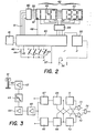
- the illustrated appliance consists of two elements, which are, on the one hand, the electronic device 10 for detecting and displaying the end of an authorized parking period, intended to remain inside the vehicle and, on the other hand, the warning device 11 to inform this motorist of the imminent expiration of said period, intended to accompany the motorist when he leaves his parked vehicle.
- the electronic device 10 which will be described in more detail with reference to FIG. 2, essentially comprises a circuit 12 for measuring time and determining the hour or fraction of a predetermined hour defining the end of the authorized parking period, a display member 13 for indicating the time of arrival as well as the departure time, and a device 14 transmitting a signal linked to said authorized parking period.
- the device 10 is permanently supplied by a voltage source 15 which can be constituted by the vehicle battery or by an independent source.
- the emitting member 14 is preferably constituted by a piezoelectric transducer designed to emit a signal in the form of trains of ultrasonic pulses.
- the train of ultrasonic pulses generated by the circuit 12 consists of a long packet of ultrasonic pulses marking the start of the sequence, followed by a number of packets of equal length, but of lower value than the first.
- the number of pulse packets which constitute the code is for example equal to the number of minutes separating the time of day from the start time displayed on the display member 13, for example reduced by a typical value of five minutes, divided by five and rounded down to the nearest whole number.
- the departure time determined by circuit 12
- the number of minutes between arrival time and departure time minus five minutes is 158 minutes.
- the number of pulse packets is thirty-one, that is, the result of dividing 158 by 5 rounded down.
- the warning device 11 comprises a receiving member 16 arranged to receive the signal emitted by the transmitting member 14.
- This member is preferably constituted by a transducer designed to convert the ultrasonic pulses picked up into electrical pulses emitted at the output 17 of the 'receiving member 16.
- These pulses are transmitted to a filter 18 whose tuning frequency is equal to the frequency of the pulses generated by the circuit 12, so as to eliminate the parasitic pulses.
- the pulses filtered by the filter 18 are transmitted to the input of an amplifier 19 whose role is to bring their level to a value sufficient to allow their subsequent processing by a logic circuit.
- An envelope detector 20 is connected to the output of the amplifier 19 and makes it possible to restore, from pulse packets corresponding to the ultrasonic pulse trains, a pulse train of defined length.
- the output of the envelope detector 20 is on the one hand connected to a logic circuit 21 and on the other hand to one of the inputs of an AND gate 22.
- the logic circuit 21 comprising in particular a pulse duration discriminator, supplies a signal on its output 23 when a pulse of length at least equal to that of the nominal initial pulse is received by the receiving member 16.
- the output 23 of the logic circuit is connected to the other input of the door 22.
- Another output 24 is connected to a counter 25 and makes it possible to transmit to this counter a reset pulse whose presence is linked to the signal transmitted to the output 23 and which will be used to reset counter 1a in a well defined state, enabling it to receive a signal co 'sponding to a new pulse train.
- a third output 26 of the logic circuit 21 is connected to an input of a flip-flop 27 to allow as secure the locking of a member 28 emitting a warning signal which may for example consist of an audible, tactile or light alarm signal.
- the AND gate 22 transmits loading signals from the counter 25 only when the logic circuit 21 emits a signal, called the validity signal, at the output 23.
- a divider element 29 comprises for example a quartz oscillator followed by several divider circuits making it possible to have well-defined frequency signals, used respectively by the various components to which it is connected.
- One of the frequencies available at the output of the dividing element 29 corresponds for example to a pulse every five minutes, which is directly linked to the input 32 of the counter 25 to cause the counting of the value loaded by means of the train of pulses, which will have the effect, in the absence of new loads, of bringing the state of the counter to zero after a time counted in minutes, equal to the number loaded multiplied by five.
- This zero state corresponds to the appearance of a signal emitted at the output 33 of the counter 25, this signal being intended for the alarm generated by the member 28 emitting a warning signal.
- the signal emitted at the output 33 of the counter causes a change of state of the flip-flop 27, the output of which is connected to the logic circuit 31 serving to select an audible frequency, a slow pulse and a limit duration of the alarm at through these connections with the divider element 29.
- the corresponding signal is sent to an amplifier 34 directly connected to the member 28.
- a switch 35 constituted for example by a push button, makes it possible to interrupt the warning signal at will. sound or light or turn off the alarm entirely.
- the transmitter 14 and the receiver 16 are designed such that the range of the information transmitted from one to the other is relatively small. Indeed, the countdown operation should start as soon as the link between the transmitter 14 and the receiver 16 is interrupted, that is to say when the motorist leaves his parked vehicle.
- the electronic device for determining and displaying the end of an authorized parking period essentially consists of a microprocessor 40 or an equivalent circuit associated with a clock 41 serving as a time base and supplying in particular the clock signals necessary for the operation of the microprocessor 40, and of a display device 42 arranged to simultaneously display the arrival time or possibly a time interval within which the arrival time and the departure corresponding to the end of the authorized parking time.
- switches 43 can be brought into contact with corresponding inputs of the microprocessor 40, to allow modification of the internal registers corresponding respectively to tens of hours, hours, tens of minutes and minutes. By these switches, it is possible to reset the time of the device, provided however that the contactor 44 is in a "time setting" position, in which it closes the circuit corresponding to the input 45 of the microprocessor 40.
- the operating mode of the device can be modified for use based on parking rules different from those of the blue zone, especially those corresponding to the so-called red zone.
- This mode of use is advantageously displayed by means of an indicator light 47 or any other suitable member fitted to the display device 42.
- the member 47 is controlled by means of an electrical connection with the microprocessor 40, indicated by line 48.
- a pilot decoder is mounted, the function of which is to transform a decimal coded information conveyed by the four lines 51 linking the microprocessor 40 to the decoder 50 in a representation in numbers composed using seven segments, the control signals of which are transmitted by the seven lines 52.
- the display device 42 further comprises a screen 53 on which the departure time is displayed.
- a demultiplexer 54 mounted between the microprocessor 40 and the display device 42, makes it possible to control the display only with one digit at a time, the use of a multiplexed display mode making it possible to limit the number of electrical connections between the microprocessor 54 and the display device 42.
- the display device is represented in the form of two screens 49 and 53, it could consist of a single screen, the selection of the figures intended to display the arrival time or departure time being carried out by means of the demultiplexer 54.
- the integration methods known per se make it possible to combine the functions of the pilot decoder and of the multiplexer or of the pilot decoder, of the multiplexer and of the microprocessor.
- a stabilizer 55 connected to the microprocessor 40, is intended to stabilize the supply voltage of the source 56 and to bring it to a level sufficient to allow the correct operation of the various components of the system described above.
- the microprocessor 40 further comprises an input 57, by which an external information is transmitted to it signifying that the vehicle is in motion or at a standstill.
- This external information is used to control the display of the time of day on the corresponding display screen 49, as well as the control of the display of the departure time determined as a function of the arrival time.
- This command is carried out at regular intervals, as long as the signal brought to the input 57 indicates that the vehicle is in circulation.
- this stop being determined by any sensor, such as for example an accelerometer which will be described below with reference to FIG.
- the external information is no longer transmitted
- the arrival time displayed on the screen 49 is the time of day when the circulation of the vehicle ended, that is to say the time to which parking begins
- the starting time displayed on screen 53 is the time calculated by the device and defining the time limit for authorized parking.
- internal registers, controlled by the clock 41 continue to keep the time of day, so that it can be displayed as mentioned previously when the vehicle is restarted.
- the microprocessor 40 is programmed in such a way that it functions exactly like a parking disk in the blue zone or in the red zone.
- the day is divided into a number of time intervals, each of which is linked to a specific time which is the end time for authorized parking.
- the microprocessor determines in which of these time intervals falls the time of day at which the parking period begins, that is to say the time of arrival of the automobile on the parking area.
- the microprocessor establishes the correspondence between this time interval and the mandatory start time of the automobile and controls the display of this start time.
- the input 57 of the microprocessor 40 intended to receive said external information
- a sensor such as for example an accelerometer capable of determining at any time whether the vehicle is on or off.
- an accelerometer capable of determining at any time whether the vehicle is on or off.
- An accelerometer makes it possible to detect the various accelerations and to deduce therefrom whether the vehicle is in traffic, stationary or if it has been subjected to an impact while it was stationary. Such equipment is advantageously used to provide the external information transmitted to the input 57.
- this equipment consists of a piezoelectric element 60 to which a mass 61 is mechanically linked.
- This mass is connected to the piezoelectric element 60 in such a way that any accelerated positive or negative ration generates a force capable of elastic deformation of the piezoelectric element.
- This element is arranged in such a way that its sensitivity to lateral accelerations undergone by the vehicle is extremely low, while the sensitivity to accelerations parallel to the axis of the vehicle is maximum.
- the deformation of the piezoelectric element develops, in a manner known per se, a potential difference between its electrodes.
- This potential difference is amplified by an amplifier 62, then filtered by a low-pass type filter 63, the function of which is to eliminate parasitic oscillations and to keep only those which correspond to normal accelerations such as undergoes them. vehicle in normal traffic.
- the high frequency components caused for example by vibrations of the vehicle when it is parked and another vehicle passes nearby, are eliminated by the filter 63.
- the signal from the filter 63 is then amplified by a chain of amplifiers comprising for example the two amplifiers 64 and 63.
- This amplified signal is transmitted to the input of a window comparator constituted by two comparator elements 66 and 67.
- This comparator makes it possible to define the sign of the alteration suffered by the vehicle.
- the output of the comparator element 66 will for example be active when the vehicle undergoes a positive acceleration, while the output of the comparator element 67 will in this case be active when the vehicle undergoes a deceleration.
- the outputs of the two comparator elements are respectively connected to two monostable elements 68 and 69.
- the corresponding monostable forms a pulse of a certain duration T 1 defined as a function of the time constant of the piezoelectric element 60.
- This pulse has the effect of inhibiting the monostable element corresponding to the acceleration of contrary signs which is induced by the elasticity of the piezoelectric element. Thanks to the symmetrical mounting of the two monostable elements 68 and 69, each appearance of a first signal corresponding to an acceleration blocks, for a duration T 1 , the signal corresponding to a deceleration.
- the outputs of the monostable elements 68 and 69 are connected to the inputs of two other monostable elements 70 and 71.
- the function of these two additional monostable elements 70 and 71 consists in defining the duration of a time interval T 2 greater than T l , during which the device collects information relating to the movements of the vehicle. If, during the time interval T 2 , the device detects at least two accelerations of opposite signs, it will provide, at input 57 of the microprocessor (see fig. 2), external information signifying that the vehicle is in normal circulation . This information is transmitted by means of two AND logic gates 72 and 73.
- the output of one of the monostable elements 70 or 71 When the output of one of the monostable elements 70 or 71 is activated indirectly by an acceleration of a certain sign, it transmits a validity signal on one of the inputs of the corresponding logic gates 72 or 73. If a signal corresponding to an acceleration of opposite sign appears during the time interval T2 on the other input of the AND logic gate, a signal may be emitted at the output of this gate.
- the two outputs of logic gates 72 and 73 are connected to the inputs of an OR logic gate 74.
- the output of logic gate 74 therefore provides a signal whenever at least two accelerations of opposite signs have appeared during the interval time T 2 , thus signaling to the electronic device described above that the vehicle is traveling normally. The absence of acceleration and corresponding signal means that the vehicle is parked.
- the transmission of the external information signal to the device illustrated in FIG. 2 can be carried out by a direct electrical connection, for example the contactor actuated by the ignition key.
- the accelerometer of FIG. 3 is integrated into the circuit of FIG. 2.
- the diagram of the above device could be modified and that certain components or groups of components could be replaced by one or more equivalent components, in particular in the case of the application of integration techniques.
Landscapes
- Physics & Mathematics (AREA)
- General Physics & Mathematics (AREA)
- Time Recorders, Dirve Recorders, Access Control (AREA)
- Emergency Alarm Devices (AREA)
- Lock And Its Accessories (AREA)
- Burglar Alarm Systems (AREA)
Priority Applications (3)
| Application Number | Priority Date | Filing Date | Title |
|---|---|---|---|
| AT83810622T ATE29322T1 (de) | 1983-12-27 | 1983-12-27 | Individuelles geraet zur parkzeitkontrolle. |
| EP83810622A EP0146664B1 (de) | 1983-12-27 | 1983-12-27 | Individuelles Gerät zur Parkzeitkontrolle |
| DE8383810622T DE3373375D1 (en) | 1983-12-27 | 1983-12-27 | Personal device for parking time control |
Applications Claiming Priority (1)
| Application Number | Priority Date | Filing Date | Title |
|---|---|---|---|
| EP83810622A EP0146664B1 (de) | 1983-12-27 | 1983-12-27 | Individuelles Gerät zur Parkzeitkontrolle |
Publications (2)
| Publication Number | Publication Date |
|---|---|
| EP0146664A1 true EP0146664A1 (de) | 1985-07-03 |
| EP0146664B1 EP0146664B1 (de) | 1987-09-02 |
Family
ID=8191586
Family Applications (1)
| Application Number | Title | Priority Date | Filing Date |
|---|---|---|---|
| EP83810622A Expired EP0146664B1 (de) | 1983-12-27 | 1983-12-27 | Individuelles Gerät zur Parkzeitkontrolle |
Country Status (3)
| Country | Link |
|---|---|
| EP (1) | EP0146664B1 (de) |
| AT (1) | ATE29322T1 (de) |
| DE (1) | DE3373375D1 (de) |
Cited By (7)
| Publication number | Priority date | Publication date | Assignee | Title |
|---|---|---|---|---|
| GB2185137A (en) * | 1985-12-28 | 1987-07-08 | Kazuo Sato | A parking meter |
| EP0297531A1 (de) * | 1987-07-03 | 1989-01-04 | Nardino Righi | Elektronische Parkzeitanzeigevorrichtung für Autos |
| EP1229501A1 (de) * | 2001-01-31 | 2002-08-07 | Parking Partners Ltd. | Parksystem mit automatischen Ankündigungen an den Fahrer eines Fahrzeugs |
| WO2003048873A1 (en) * | 2001-12-05 | 2003-06-12 | Florix Technology Limited | Supply current usage control system |
| EP1231572A3 (de) * | 2001-02-10 | 2003-07-09 | Peter Gautsch | Parkscheibe für Kraftfahrzeuge |
| EP1221676A3 (de) * | 2000-10-11 | 2003-10-08 | Ermanno Bini Chiesa | Automatische Parkscheibe |
| EP1638053A1 (de) * | 2004-09-20 | 2006-03-22 | Matsushita Electric Industrial Co., Ltd. | Automatisches Parkzeit Informationssystem |
Citations (6)
| Publication number | Priority date | Publication date | Assignee | Title |
|---|---|---|---|---|
| US987773A (en) * | 1910-08-02 | 1911-03-28 | William F Templeton | Churn. |
| US3049864A (en) * | 1960-02-05 | 1962-08-21 | Michel Conchon | Parking meter |
| DE2822002A1 (de) * | 1977-05-20 | 1979-04-05 | Sharp Kk | Elektronischer zeitgeber |
| DE2811456A1 (de) * | 1978-03-14 | 1979-09-20 | Schlegel | Parkscheibe fuer kraftfahrzeuge |
| DE2851596A1 (de) * | 1978-11-29 | 1980-06-12 | Dettwiler Hans | Parkuhr fuer die verwendung bei kraftfahrzeugen |
| FR2478842A1 (fr) * | 1980-03-24 | 1981-09-25 | Ebauches Sa | Dispositif signalisateur de temps de parcage |
-
1983
- 1983-12-27 EP EP83810622A patent/EP0146664B1/de not_active Expired
- 1983-12-27 AT AT83810622T patent/ATE29322T1/de not_active IP Right Cessation
- 1983-12-27 DE DE8383810622T patent/DE3373375D1/de not_active Expired
Patent Citations (6)
| Publication number | Priority date | Publication date | Assignee | Title |
|---|---|---|---|---|
| US987773A (en) * | 1910-08-02 | 1911-03-28 | William F Templeton | Churn. |
| US3049864A (en) * | 1960-02-05 | 1962-08-21 | Michel Conchon | Parking meter |
| DE2822002A1 (de) * | 1977-05-20 | 1979-04-05 | Sharp Kk | Elektronischer zeitgeber |
| DE2811456A1 (de) * | 1978-03-14 | 1979-09-20 | Schlegel | Parkscheibe fuer kraftfahrzeuge |
| DE2851596A1 (de) * | 1978-11-29 | 1980-06-12 | Dettwiler Hans | Parkuhr fuer die verwendung bei kraftfahrzeugen |
| FR2478842A1 (fr) * | 1980-03-24 | 1981-09-25 | Ebauches Sa | Dispositif signalisateur de temps de parcage |
Cited By (7)
| Publication number | Priority date | Publication date | Assignee | Title |
|---|---|---|---|---|
| GB2185137A (en) * | 1985-12-28 | 1987-07-08 | Kazuo Sato | A parking meter |
| EP0297531A1 (de) * | 1987-07-03 | 1989-01-04 | Nardino Righi | Elektronische Parkzeitanzeigevorrichtung für Autos |
| EP1221676A3 (de) * | 2000-10-11 | 2003-10-08 | Ermanno Bini Chiesa | Automatische Parkscheibe |
| EP1229501A1 (de) * | 2001-01-31 | 2002-08-07 | Parking Partners Ltd. | Parksystem mit automatischen Ankündigungen an den Fahrer eines Fahrzeugs |
| EP1231572A3 (de) * | 2001-02-10 | 2003-07-09 | Peter Gautsch | Parkscheibe für Kraftfahrzeuge |
| WO2003048873A1 (en) * | 2001-12-05 | 2003-06-12 | Florix Technology Limited | Supply current usage control system |
| EP1638053A1 (de) * | 2004-09-20 | 2006-03-22 | Matsushita Electric Industrial Co., Ltd. | Automatisches Parkzeit Informationssystem |
Also Published As
| Publication number | Publication date |
|---|---|
| EP0146664B1 (de) | 1987-09-02 |
| DE3373375D1 (en) | 1987-10-08 |
| ATE29322T1 (de) | 1987-09-15 |
Similar Documents
| Publication | Publication Date | Title |
|---|---|---|
| FR2685958A1 (fr) | Appareil portatif et autonome pour la detection et l'enregistrement de phenomenes de courte duree se produisant aleatoirement. | |
| EP0988160B1 (de) | Reifen kontroll system durch beschleunigungsmessung | |
| FR2458429A1 (fr) | Dispositif indicateur pour vehicules automobiles | |
| EP0146664B1 (de) | Individuelles Gerät zur Parkzeitkontrolle | |
| FR2628856A1 (fr) | Ensemble formant montre-bracelet et ordinateur pour la pratique du cyclisme | |
| FR2917214A1 (fr) | Systeme d'etude de l'utilisation d'emplacements de stationnement et de gestion en temps reel de tels emplacements | |
| FR2717595A3 (fr) | Dispositif électronique de gestion des temps de conduite et de repos pour véhicule routier de type "poids-lourd". | |
| FR2532592A1 (fr) | Installation de circuits pour la surveillance de la pression de pneumatiques pour vehicules automobiles | |
| FR2579335A1 (fr) | Radio-pendule | |
| WO1997016115A1 (fr) | Procede pour evaluer et/ou mesurer la vitesse de reaction d'un etre vivant et dispositif pour la mise en oeuvre de ce procede | |
| FR2662321A1 (fr) | Dispositif de radiocommunication et appareil auxiliaire pour ce dispositif. | |
| EP0904575B1 (de) | Verfahren und vorrichtung zur steuerung der flughöhe eines flugzeugs | |
| FR2498999A1 (fr) | Dispositif de surveillance anti-sommeil pour automobiles et transport routier et autres | |
| EP0954770A1 (de) | Uhr mit detektions- und sparvorrichtungen im falle von nicht ausreichender energieversorgung | |
| FR2870521A1 (fr) | Systeme et procede de surveillance de zones interieures d'un avion, interface d'utilisateur pour un tel systeme, et avion equipe d'un tel systeme | |
| WO2004114225A1 (en) | Electronic parking disc | |
| EP0159306A1 (de) | Vorrichtung zum Überwachen der Einnahme von Pillen | |
| FR2976497A1 (fr) | Accessoire limiteur de temps de jeu | |
| GB2135482A (en) | Timer | |
| FR2639111A1 (fr) | Dispositif de controle de niveau d'un recepteur de charge sur un appareil de pesage | |
| FR2478842A1 (fr) | Dispositif signalisateur de temps de parcage | |
| FR2664716A1 (fr) | Procede et dispositif pour controler le deplacement d'un mobile par rapport a un autre mobile. | |
| FR2939897A3 (fr) | Procede de comptage du nombre d'atterrissages d'un pneumatique d'aeronef patch pneumatique et roue avec compteur d'atterrissages | |
| FR2636156A1 (fr) | Procede et dispositif pour la mesure et la signalisation des files d'attente se creant dans une zone de passage unidirectionnel et son application a la signalisation de l'etat des remontees mecaniques dans une station de ski | |
| FR2499258A1 (fr) | Appareil electronique utilisable comme horloge numerique ou chronographe |
Legal Events
| Date | Code | Title | Description |
|---|---|---|---|
| PUAI | Public reference made under article 153(3) epc to a published international application that has entered the european phase |
Free format text: ORIGINAL CODE: 0009012 |
|
| 17P | Request for examination filed |
Effective date: 19850222 |
|
| AK | Designated contracting states |
Designated state(s): AT BE CH DE FR IT LI LU NL |
|
| 17Q | First examination report despatched |
Effective date: 19860515 |
|
| GRAA | (expected) grant |
Free format text: ORIGINAL CODE: 0009210 |
|
| AK | Designated contracting states |
Kind code of ref document: B1 Designated state(s): AT BE CH DE FR IT LI LU NL |
|
| PG25 | Lapsed in a contracting state [announced via postgrant information from national office to epo] |
Ref country code: NL Effective date: 19870902 Ref country code: AT Effective date: 19870902 |
|
| REF | Corresponds to: |
Ref document number: 29322 Country of ref document: AT Date of ref document: 19870915 Kind code of ref document: T |
|
| REF | Corresponds to: |
Ref document number: 3373375 Country of ref document: DE Date of ref document: 19871008 |
|
| PG25 | Lapsed in a contracting state [announced via postgrant information from national office to epo] |
Ref country code: BE Effective date: 19871031 |
|
| ITF | It: translation for a ep patent filed | ||
| PG25 | Lapsed in a contracting state [announced via postgrant information from national office to epo] |
Ref country code: LU Free format text: LAPSE BECAUSE OF NON-PAYMENT OF DUE FEES Effective date: 19871231 |
|
| NLV1 | Nl: lapsed or annulled due to failure to fulfill the requirements of art. 29p and 29m of the patents act | ||
| BERE | Be: lapsed |
Owner name: SCHAFFER RUDOLF Effective date: 19871231 Owner name: RACINE MARTIAL Effective date: 19871231 |
|
| PLBE | No opposition filed within time limit |
Free format text: ORIGINAL CODE: 0009261 |
|
| STAA | Information on the status of an ep patent application or granted ep patent |
Free format text: STATUS: NO OPPOSITION FILED WITHIN TIME LIMIT |
|
| 26N | No opposition filed | ||
| PGFP | Annual fee paid to national office [announced via postgrant information from national office to epo] |
Ref country code: FR Payment date: 19920721 Year of fee payment: 9 |
|
| PGFP | Annual fee paid to national office [announced via postgrant information from national office to epo] |
Ref country code: DE Payment date: 19920826 Year of fee payment: 9 |
|
| PG25 | Lapsed in a contracting state [announced via postgrant information from national office to epo] |
Ref country code: FR Effective date: 19920831 |
|
| REG | Reference to a national code |
Ref country code: FR Ref legal event code: ST |
|
| REG | Reference to a national code |
Ref country code: FR Ref legal event code: AR |
|
| PG25 | Lapsed in a contracting state [announced via postgrant information from national office to epo] |
Ref country code: DE Effective date: 19930901 |
|
| REG | Reference to a national code |
Ref country code: FR Ref legal event code: DS |
|
| PGFP | Annual fee paid to national office [announced via postgrant information from national office to epo] |
Ref country code: CH Payment date: 19980305 Year of fee payment: 15 |
|
| PG25 | Lapsed in a contracting state [announced via postgrant information from national office to epo] |
Ref country code: LI Free format text: LAPSE BECAUSE OF NON-PAYMENT OF DUE FEES Effective date: 19981231 Ref country code: CH Free format text: LAPSE BECAUSE OF NON-PAYMENT OF DUE FEES Effective date: 19981231 |
|
| REG | Reference to a national code |
Ref country code: CH Ref legal event code: PL |