EP0146700A2 - Dispositif pour fabriquer des objets en bande de matériel d'une feuille thermoplastique et utilisation de ce dispositif pour fabriquer des pièces de récipient - Google Patents
Dispositif pour fabriquer des objets en bande de matériel d'une feuille thermoplastique et utilisation de ce dispositif pour fabriquer des pièces de récipient Download PDFInfo
- Publication number
- EP0146700A2 EP0146700A2 EP84111673A EP84111673A EP0146700A2 EP 0146700 A2 EP0146700 A2 EP 0146700A2 EP 84111673 A EP84111673 A EP 84111673A EP 84111673 A EP84111673 A EP 84111673A EP 0146700 A2 EP0146700 A2 EP 0146700A2
- Authority
- EP
- European Patent Office
- Prior art keywords
- material web
- heating
- web
- punching
- film
- Prior art date
- Legal status (The legal status is an assumption and is not a legal conclusion. Google has not performed a legal analysis and makes no representation as to the accuracy of the status listed.)
- Granted
Links
- 238000004519 manufacturing process Methods 0.000 title claims description 6
- 229920001169 thermoplastic Polymers 0.000 title claims description 5
- 239000004416 thermosoftening plastic Substances 0.000 title claims description 5
- 239000000463 material Substances 0.000 claims abstract description 71
- 238000010438 heat treatment Methods 0.000 claims abstract description 47
- 238000004080 punching Methods 0.000 claims abstract description 43
- 230000004888 barrier function Effects 0.000 claims description 15
- 238000007493 shaping process Methods 0.000 claims description 9
- 230000005855 radiation Effects 0.000 claims description 8
- 238000003856 thermoforming Methods 0.000 claims description 6
- 239000004743 Polypropylene Substances 0.000 claims description 4
- -1 polypropylene Polymers 0.000 claims description 4
- 229920001155 polypropylene Polymers 0.000 claims description 4
- 229920000642 polymer Polymers 0.000 claims description 3
- 229920000219 Ethylene vinyl alcohol Polymers 0.000 claims description 2
- UFRKOOWSQGXVKV-UHFFFAOYSA-N ethene;ethenol Chemical compound C=C.OC=C UFRKOOWSQGXVKV-UHFFFAOYSA-N 0.000 claims description 2
- 239000004715 ethylene vinyl alcohol Substances 0.000 claims description 2
- 238000011144 upstream manufacturing Methods 0.000 claims description 2
- 238000006243 chemical reaction Methods 0.000 claims 2
- 229920001328 Polyvinylidene chloride Polymers 0.000 claims 1
- 239000002985 plastic film Substances 0.000 claims 1
- 229920006255 plastic film Polymers 0.000 claims 1
- 239000005033 polyvinylidene chloride Substances 0.000 claims 1
- XLYOFNOQVPJJNP-UHFFFAOYSA-N water Chemical compound O XLYOFNOQVPJJNP-UHFFFAOYSA-N 0.000 claims 1
- 238000000465 moulding Methods 0.000 abstract 1
- 238000012545 processing Methods 0.000 description 9
- 238000005520 cutting process Methods 0.000 description 6
- 238000000034 method Methods 0.000 description 5
- 238000013461 design Methods 0.000 description 3
- 239000011888 foil Substances 0.000 description 3
- 230000008569 process Effects 0.000 description 3
- 229920001986 Vinylidene chloride-vinyl chloride copolymer Polymers 0.000 description 2
- 239000002318 adhesion promoter Substances 0.000 description 2
- 238000001816 cooling Methods 0.000 description 2
- 230000000694 effects Effects 0.000 description 2
- 230000001788 irregular Effects 0.000 description 2
- 238000005096 rolling process Methods 0.000 description 2
- 238000000926 separation method Methods 0.000 description 2
- 238000010521 absorption reaction Methods 0.000 description 1
- 230000008859 change Effects 0.000 description 1
- 238000010276 construction Methods 0.000 description 1
- 230000008878 coupling Effects 0.000 description 1
- 238000010168 coupling process Methods 0.000 description 1
- 238000005859 coupling reaction Methods 0.000 description 1
- 230000007423 decrease Effects 0.000 description 1
- 238000012423 maintenance Methods 0.000 description 1
- 238000002844 melting Methods 0.000 description 1
- 230000008018 melting Effects 0.000 description 1
- 230000004048 modification Effects 0.000 description 1
- 238000012986 modification Methods 0.000 description 1
- 238000013021 overheating Methods 0.000 description 1
- 230000036316 preload Effects 0.000 description 1
- 238000003825 pressing Methods 0.000 description 1
- 230000001105 regulatory effect Effects 0.000 description 1
- 238000007665 sagging Methods 0.000 description 1
- 230000006641 stabilisation Effects 0.000 description 1
- 238000011105 stabilization Methods 0.000 description 1
- 230000000087 stabilizing effect Effects 0.000 description 1
- 238000003860 storage Methods 0.000 description 1
Images


Classifications
-
- B—PERFORMING OPERATIONS; TRANSPORTING
- B29—WORKING OF PLASTICS; WORKING OF SUBSTANCES IN A PLASTIC STATE IN GENERAL
- B29C—SHAPING OR JOINING OF PLASTICS; SHAPING OF MATERIAL IN A PLASTIC STATE, NOT OTHERWISE PROVIDED FOR; AFTER-TREATMENT OF THE SHAPED PRODUCTS, e.g. REPAIRING
- B29C51/00—Shaping by thermoforming, i.e. shaping sheets or sheet like preforms after heating, e.g. shaping sheets in matched moulds or by deep-drawing; Apparatus therefor
- B29C51/26—Component parts, details or accessories; Auxiliary operations
- B29C51/44—Removing or ejecting moulded articles
- B29C51/445—Removing or ejecting moulded articles from a support after moulding, e.g. by cutting
-
- B—PERFORMING OPERATIONS; TRANSPORTING
- B29—WORKING OF PLASTICS; WORKING OF SUBSTANCES IN A PLASTIC STATE IN GENERAL
- B29C—SHAPING OR JOINING OF PLASTICS; SHAPING OF MATERIAL IN A PLASTIC STATE, NOT OTHERWISE PROVIDED FOR; AFTER-TREATMENT OF THE SHAPED PRODUCTS, e.g. REPAIRING
- B29C51/00—Shaping by thermoforming, i.e. shaping sheets or sheet like preforms after heating, e.g. shaping sheets in matched moulds or by deep-drawing; Apparatus therefor
- B29C51/26—Component parts, details or accessories; Auxiliary operations
- B29C51/42—Heating or cooling
- B29C51/421—Heating or cooling of preforms, specially adapted for thermoforming
Definitions
- the invention relates to a device for the production of objects from a material web of a thermoplastic film and the use thereof for the production of container parts.
- the aim of the device according to the invention is to create solutions to the problems mentioned.
- the task in particular when processing multilayer films is to bring the film quickly and uniformly to the necessary softening state.
- none of the layers may be exposed to a temperature that is too high for them, since otherwise the quality of the shaped objects may suffer.
- internal, non-metallic barrier layers of the film are ge endangers.
- hot air heating is time-consuming and correspondingly requires space, and has a low thermal efficiency
- the more effective radiation heating with large-area heating has the disadvantage of uneven heating of the film as a result of local air convection between the film and the radiator. It is also difficult to adjust because the heating depends on the radiation absorption properties of the film, which are strongly influenced by the changing surface properties and storage conditions of the film. The temperature profile in the film is therefore difficult to control.
- the heating device is designed as a combination of a contact heater and a radiation heater.
- the contact heater is preferably connected upstream of the radiant heater in the web transport direction.
- the contact heater has a lower and an upper heating plate which can be brought into contact with the upper or lower side of the material web.
- a temperature profile is first impressed on the film, which decreases on both sides from the surface to the center.
- Sensitive, inner barrier layers of a multi-layer film are thus available Protected from overheating.
- the heating takes place only up to a point at which the surface temperatures of the foil allow a perfect detachment from the heating plates.
- the material web part provided with the uniform heat profile over the web surface is then subsequently put into a softening state suitable for shaping by the radiant heating, wherein essentially only an increase in the existing thermal profile is caused by the radiant heating. Influences of convection etc. therefore appear much less because the time spent in the radiation field is shortened compared to conventional radiation heating and the radiation field can be reduced.
- this heating device is preferably used for processing a polypropylene multilayer film with an inner barrier layer made of vinylidene chloride-vinyl chloride copolymers (Saran), since the barrier layer has a lower softening or melting temperature than the outer layer.
- an inner barrier layer made of vinylidene chloride-vinyl chloride copolymers (Saran)
- the barrier layer has a lower softening or melting temperature than the outer layer.
- it is not limited to this.
- the punch-out device has a pre-cutting point and a resharpened, centered circumferential punching point, the objects formed from the material web being separated from one another at least in some areas in the pre-cutting point be punched into their final circumference in the circumferential punching point after fitting into a centering arrangement.
- the individual objects can be fitted into the centering device independently of one another, so that individual positioning is possible independently of any irregular dimensional shrinkage in the material web.
- the positioned objects can then be brought to their exact circumferential shape with a punching knife adjusted to the centering device.
- the transport device solves the above-mentioned problem in that it has drive wheels connected to a common drive on both sides along the material web, each of which is supported against an associated sprung or fixed roller, the material web between the drive wheels and the rollers being detectable.
- the drive wheels are preferably toothed on their periphery and each roller is ge with an adjustable bias against the associated driving wheel, the engagement surface of the wheel being dimensioned such that it at least partially penetrates into the material web to create line contact at the given pretension.
- the drive wheels can be arranged at an angle to the direction of transport. This drive allows an exactly maintainable stride length even with intermittent drive.
- thermoplastic film which contains the aforementioned heating device, punching device and transport device in combination, will now be described with reference to the accompanying drawing. According to the above and following explanations, however, each of these devices can also be used without the other two.
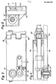
- the device shown which is first described with reference to the first two figures, has essentially five successive processing stations 1 to 5.
- a roll support arrangement for a material roll of known construction is provided (not shown). It is for material rolls with a width of 560 mm, for example and a diameter of 1200 mm. Since the material is transported through the device in steps, a compensation point is arranged downstream of the roll support arrangement, where one step length of the material strip can be temporarily stored. The rolling speed of the roll can thus remain essentially constant, and the rolling speed can be adapted to the respective roll diameter by means of light barriers.
- the material web is then gripped by the lateral transport device 6 and conveyed in steps by the device.
- the first processing point is a contact heater 1 with two heated plates 10 and 11, between which the film 7 can be clamped.
- the electrical heating of the plates can be regulated independently of one another to an adjustable setpoint.
- the two plates 10, 11 can intermittently clamp and release the film 7 with a selectable pressing pressure.
- at least one of the plates, in the figure the upper plate 10, is provided with a corresponding hydraulic or pneumatic system.
- the temperature and the contact pressure of the plates are set so that the heating required for the respective material takes place in the intended step duration of, for example, 4 seconds.
- the sizes mentioned are set so that the desired temperature profile is formed in the film.
- the film In the contact heater, the film is heated uniformly over essentially the entire working surface, but not yet to the softening point. This prevents the film from sticking to the plates 10, 11.
- the material web reaches the radiation heater 2 in the next working step.
- This consists of medium-wave radiators 21 arranged on both sides of the film 7, which are arranged in a housing 22 to reduce air convection.
- the remaining heating to the softening point of the film can thus take place within the available step time.
- the transverse expansion of the film that occurs in this area which is exacerbated by the effect of its own weight, can lead to a sag, through which the distances between the film and the radiator are changed.
- two measures can be provided: one consists in supporting the film in its central area by at least one accompanying support element.
- two traveling wire ropes 23 are provided for this purpose, which are guided from below to the film via deflection or drive rollers 24 before the radiant heating and support this up to the shaping device 3.
- a local transverse stretching can be effected by means of a transport device in the area of the radiant heating, as will be explained in detail later.
- the two-stage heating described ensures optimum heating, in particular for multilayer films. While the contact heating of the film quickly and energy-saving imprints a temperature profile, the radiant heating finally brings the stable cover films to the ideal softening temperature without damaging the inner (barrier) films.
- this heater has proven itself for processing a multilayer film, in which a barrier film made of Saran (a vinylidene chloride-vinyl chloride copolymer) is bonded to polypropylene outer films by means of an adhesion promoter, the total film thickness being approx. 900 pm.
- Saran a vinylidene chloride-vinyl chloride copolymer
- an adhesion promoter the total film thickness being approx. 900 pm.
- other barrier polymers such as EVOH can also be used.
- the shaping can take place in a subsequent thermoforming device 3 in a manner known per se. This is designed in such a way that it is possible to work with vacuum deformation both in the positive and in the negative process, and on the other hand it is also possible to use pressure to carry out air deformation.
- the punching device can be integrated directly in the thermoforming device or, as in the exemplary embodiment described, can be carried out in one or more subsequent work steps.
- a toggle arrangement (not shown) allows the molds to be opened and closed.
- 1 is designed for compressed air deformation.
- recesses 33 are formed for the simultaneous shaping of six shell-like container parts.
- Channels for the wire cables 23 are provided between the recesses 33.
- the individual recesses can be closed airtight by means of an upper plate 34, after which the shells are formed by means of compressed air.
- the punching device is separated from the thermoforming device so that the film can cool down sufficiently before punching out, otherwise the still soft barrier film adheres to the punching tool and pulls threads.
- the punching device is designed in such a way that, despite irregular shrinkage of the film when cooling after thermoforming, the same, defined outer circumference is achieved for each container.
- the material web between the shaped containers is partially separated so that these containers still carried by the material web can be positioned independently of one another in the actual circumferential punching point.
- a pre-punching point 4 and a subsequent circumferential punching point 5 are provided.
- the pre-punching point 4 can also be used for the final circumferential punching if the processed film allows this. In the case of foils with strong shrinkage, however, it is only used for pre-punching and leaving Predetermined breaking points 21 between the individual container parts or the material web. It consists of an upper and a lower stamped part 42 and 43, both of which are retractable from the material web. In the upper stamped part 42, which can be heated, a cutting edge 44 is inserted in accordance with the desired pre-punching and works against corresponding surfaces on the lower stamped part 43. After the pre-punching, the pre-shaped container parts connected to the material strip at the predetermined breaking points reach the circumferential punching point 5 in the next working step.
- the container parts are pressed first by Brechstem p el 51 broken out of the material strip 7 and to understand or handle in a lower centering arrangement 52nd Immediately after centering, the circumferential punching is carried out by a knife 54 arranged on an upper punch 53, which corresponds to the exact circumference of the container parts. The container parts are then carried away in a conventional manner (not shown) and stacked on a stacking station 8. The remaining strip material is rolled up on the exit side (not shown).
- FIGS. 6 to 8 show a second exemplary embodiment, which shows a further variant of the punching out of the shells following the thermoforming device 3.
- the material web 7 with the shells molded therein is first separated by cutting rollers 70, 71 between longitudinal rows of shells into individual webs, so that each of the individual webs can be moved transversely to the transport direction independently of the others for lateral positioning of the shells during the subsequent circumferential punching in the circumferential punching point 5 '.
- the cutting rollers 70, 71 are profiled (FIG. 8) such that a narrow strip is cut out of the material web during the separation.
- After the cutting rollers 70, 71 is a roller 72 provided, which pushes the material webs slightly out of the plane.
- the circumferential punching point 5 ' is shown schematically in cross section in FIG. 7 for a single shell. It has a positioning and ejection part 73 arranged under the material web, a stamping part 74 arranged above it and a magazine 75 for the finished punched-out shells. When the material web 7 is transported, the positioning and ejection part 73 and the stamping part 74 remain lifted off the web.
- the positioning and ejection part 74 is first raised from below against the shells, which are aligned in the corresponding recesses 76 owing to their lateral and longitudinally acting shaft. Thereafter, the circumferential punching is carried out by lowering the stamped part 74. The punched-out shells are then moved by means of an ejector 77 through the stamped part 74 into the magazine 75 located at the top, and are brought there from below to the respective stack of shells which is held in the magazine by elastic projections 78 . After the ejector 77 is withdrawn, the work cycle is ended. The remaining strip material is rolled up on a roll 79.
- the described punching methods are suitable, regardless of the design of the preceding heating device, for the exact circumferential punching of thermoformed objects, which change in their masses when cooled, by means of centering these undesirable and difficult-to-see effects can be eliminated.
- the transport of the material web through the device is accomplished with a device 6, which can be seen in detail from FIGS. 3 to 5.
- the transport device 6 runs along the entire length of the material web on both sides Device and engages on the edge of the material web lying outside the shaping zone.
- the transport device now has drive wheels 61 distributed along the device, each of which is supported against a corresponding support roller 62.
- the material web 7 is gripped between the drive wheels and the support rollers, as can best be seen in FIG. 5.
- Each support roller 62 is loaded with an adjustable preload against its drive wheel 61. This, as shown in Fig. 3, hfitun by the up g of the support roller 62 can be achieved on a pivot lever 62 which by means of a pneumatic cylinder is charged Kclben owned 64th
- the support rollers 62 are preferably provided with ball bearings in order to achieve low transport resistance.
- the driving wheels have fine teeth on their wedge-shaped circumference to increase the friction against the film.
- the contact surface on the circumference is matched to the load on the support roller 62 in such a way that the drive wheels partially penetrate into the material web in order to create a line engagement.
- the wedge-shaped design of the engagement area of the drive wheels also prevents the material strip from sliding out during the processing steps in which lateral forces can occur in the material strip.
- the drive wheels are driven rigidly by one drive shaft 66 each via two bevel gears 67. The rigid drive ensures exact compliance with the selected step length and requires little maintenance.
- the transport device is fastened in a support element 65, which on a machine frame (not ge shows) is attached.
- the support element 65 can be provided with a hinge 69 at the required points and the drive shaft 66 with a toothed coupling 68 serving as a spherical joint be.
- hinges or joints are provided before and after the radiant heater 2, so that in this area the drive wheels 62 can be arranged at an angle to the direction of transport, with the corresponding transverse conveyance as a rim.
- the transport device 6 described can not only be used in connection with the system parts described above, but is generally suitable for the material web transport.
- the device described here for producing objects from a material web of a thermoplastic film is particularly suitable for processing multilayer films with heat-sensitive inner layers.
- a film is, for example, a laminate with a thickness of 900 ⁇ m made of polypropylene cover films which are bonded to an internal barrier layer made of Saran by means of an adhesion promoter.
- Such relatively thick multilayer films which are suitable for the production of food containers because of the good barrier properties, were previously difficult to process because of the difficult thermal behavior of the film.
- the present device now allows this in a flawless manner, which is particularly due to the two-step off design of the heating and punching devices is returned.
Landscapes
- Engineering & Computer Science (AREA)
- Mechanical Engineering (AREA)
- Blow-Moulding Or Thermoforming Of Plastics Or The Like (AREA)
- Perforating, Stamping-Out Or Severing By Means Other Than Cutting (AREA)
- Laminated Bodies (AREA)
- Moulds For Moulding Plastics Or The Like (AREA)
- Containers And Plastic Fillers For Packaging (AREA)
Priority Applications (1)
| Application Number | Priority Date | Filing Date | Title |
|---|---|---|---|
| AT84111673T ATE52058T1 (de) | 1983-10-06 | 1984-09-29 | Vorrichtung zur herstellung von gegenstaenden aus einer materialbahn einer thermoplastischen folie und die verwendung derselben zur herstellung von behaelterteilen. |
Applications Claiming Priority (2)
| Application Number | Priority Date | Filing Date | Title |
|---|---|---|---|
| CH545183 | 1983-10-06 | ||
| CH5451/83 | 1983-10-06 |
Related Child Applications (2)
| Application Number | Title | Priority Date | Filing Date |
|---|---|---|---|
| EP88111517A Division EP0305714A3 (fr) | 1983-10-06 | 1984-09-29 | Dispositif pour mouler des objets dans un matériau thermoplastique |
| EP88111517.4 Division-Into | 1988-07-18 |
Publications (3)
| Publication Number | Publication Date |
|---|---|
| EP0146700A2 true EP0146700A2 (fr) | 1985-07-03 |
| EP0146700A3 EP0146700A3 (en) | 1985-11-06 |
| EP0146700B1 EP0146700B1 (fr) | 1990-04-18 |
Family
ID=4293809
Family Applications (2)
| Application Number | Title | Priority Date | Filing Date |
|---|---|---|---|
| EP84111673A Expired - Lifetime EP0146700B1 (fr) | 1983-10-06 | 1984-09-29 | Dispositif pour fabriquer des objets en bande de matériel d'une feuille thermoplastique et utilisation de ce dispositif pour fabriquer des pièces de récipient |
| EP88111517A Withdrawn EP0305714A3 (fr) | 1983-10-06 | 1984-09-29 | Dispositif pour mouler des objets dans un matériau thermoplastique |
Family Applications After (1)
| Application Number | Title | Priority Date | Filing Date |
|---|---|---|---|
| EP88111517A Withdrawn EP0305714A3 (fr) | 1983-10-06 | 1984-09-29 | Dispositif pour mouler des objets dans un matériau thermoplastique |
Country Status (6)
| Country | Link |
|---|---|
| US (1) | US4778372A (fr) |
| EP (2) | EP0146700B1 (fr) |
| JP (2) | JPS60155426A (fr) |
| AT (1) | ATE52058T1 (fr) |
| CA (1) | CA1247320A (fr) |
| DE (1) | DE3481978D1 (fr) |
Cited By (4)
| Publication number | Priority date | Publication date | Assignee | Title |
|---|---|---|---|---|
| EP0241002A3 (fr) * | 1986-04-07 | 1989-07-12 | Sumitomo Bakelite Company Limited | Procédé pour la fabrication de récipients faciles à ouvrir |
| DE3836788C1 (en) * | 1988-04-25 | 1989-08-31 | Paul Kiefel Gmbh, 8228 Freilassing, De | Apparatus for preheating plastic films |
| EP0521574A1 (fr) * | 1991-07-04 | 1993-01-07 | Tw Packaging Twente B.V. | Procédé et dispositif pour fabriquer des objets à partir d'une bande thermoplastique |
| WO1997048544A1 (fr) * | 1996-06-20 | 1997-12-24 | Tetra Laval Holdings & Finance S.A. | Dispositif pour produire des couvercles cupuliformes a partir d'une bande pelliculaire en plastique |
Families Citing this family (37)
| Publication number | Priority date | Publication date | Assignee | Title |
|---|---|---|---|---|
| US4937021A (en) * | 1988-09-19 | 1990-06-26 | Shell Oil Company | Laminated billet process |
| US5571473A (en) * | 1989-12-28 | 1996-11-05 | Idemitsu Petrochemical Co., Ltd. | Process for thermoforming thermoplastic resin sheet |
| IE68430B1 (en) * | 1990-08-12 | 1996-06-12 | Polysheet Ireland Ltd | A method and apparatus for forming an article of PET material |
| US5167980A (en) * | 1991-04-24 | 1992-12-01 | Recot, Inc. | Horizontal extrusion of edge rippled snack product |
| US5238382A (en) * | 1991-08-20 | 1993-08-24 | Highland Supply Corporation | Sheet fed article forming system |
| DE4236152A1 (de) * | 1992-10-27 | 1994-04-28 | Krupp Bellaform Maschbau | Verfahren und Vorrichtung zum Ausstanzen von Formkörpern |
| DE9215136U1 (de) * | 1992-11-06 | 1993-06-03 | Meier, Peter H., 32049 Herford | Anlage zur Herstellung von Formkörpern aus einem verformbaren Folienmaterial o.dgl. |
| CA2115284A1 (fr) * | 1993-12-09 | 1995-06-10 | Mark Kevin Melius | Article forme pour l'incontinence et methode de fabrication |
| US5607415A (en) * | 1994-08-18 | 1997-03-04 | Kimberly-Clark Corporation | Flexible absorbent article |
| US5545156A (en) * | 1994-12-22 | 1996-08-13 | Kimberly-Clark Corporation | Absorbent article having a preformed member |
| US5613961A (en) * | 1994-12-30 | 1997-03-25 | Kimberly-Clark Corporation | Thin, curved absorbent article having elasticized edges |
| US5526935A (en) * | 1995-02-15 | 1996-06-18 | Minnesota Mining And Manufacturing Company | Component carrier tape |
| US5795281A (en) | 1996-07-17 | 1998-08-18 | Southpac Trust International, Inc. | Apparatus and method for automatically forming an article |
| GB9620626D0 (en) * | 1996-10-03 | 1996-11-20 | Anson Packaging Ltd | Thermoforming apparatus |
| US6091054A (en) * | 1997-03-03 | 2000-07-18 | Abbott Laboratories | Heater plate and method for using same |
| US6129538A (en) | 1997-05-01 | 2000-10-10 | Emerging Technologies Trust | Pre-cut roll and thermoformer machine |
| US6490844B1 (en) | 2001-06-21 | 2002-12-10 | Emerging Technologies Trust | Film wrap packaging apparatus and method |
| JP4095785B2 (ja) * | 2001-10-22 | 2008-06-04 | 出光ユニテック株式会社 | 包装容器の製造装置、包装容器の製造方法およびこの製造方法によって得られた包装容器 |
| US6675527B1 (en) * | 2002-01-14 | 2004-01-13 | George N. Barere | Enclosed pest control device |
| MY144621A (en) * | 2003-04-01 | 2011-10-14 | Adaptsys Ltd | Plastic embossed carrier tape apparatus and process |
| US20040209123A1 (en) * | 2003-04-17 | 2004-10-21 | Bajorek Christopher H. | Method of fabricating a discrete track recording disk using a bilayer resist for metal lift-off |
| US7686606B2 (en) * | 2004-01-20 | 2010-03-30 | Wd Media, Inc. | Imprint embossing alignment system |
| US7329114B2 (en) * | 2004-01-20 | 2008-02-12 | Komag, Inc. | Isothermal imprint embossing system |
| US7987653B2 (en) * | 2004-03-03 | 2011-08-02 | Adaptsys Limited | Plastic embossed carrier tape process |
| US7785092B2 (en) * | 2005-08-09 | 2010-08-31 | Coopervision International Holding Company, Lp | Systems and methods for producing contact lenses from a polymerizable composition |
| US8926310B2 (en) * | 2007-10-23 | 2015-01-06 | Jere F. Irwin | Cup thermoforming machine |
| DE102008062199A1 (de) * | 2008-05-29 | 2009-12-03 | Fraunhofer-Gesellschaft zur Förderung der angewandten Forschung e.V. | Verfahren und Heizeinrichtung zum Thermoformen |
| DE102008033799A1 (de) * | 2008-07-18 | 2010-02-04 | Kourtoglou S.A., Nea Kios | Verfahren und Einrichtung zum Herstellen von etikettierten, foliengeformten Behältern, insbesondere zum In-Mold-Etikettieren von foliengeformten Behältern, Etikett hierfür und etikettierter Behälter |
| US8518202B2 (en) * | 2008-07-23 | 2013-08-27 | Lrm Industries International, Inc. | Method and apparatus for forming a shaped multilayered molded article |
| US9330685B1 (en) | 2009-11-06 | 2016-05-03 | WD Media, LLC | Press system for nano-imprinting of recording media with a two step pressing method |
| US8402638B1 (en) | 2009-11-06 | 2013-03-26 | Wd Media, Inc. | Press system with embossing foil free to expand for nano-imprinting of recording media |
| US8496466B1 (en) | 2009-11-06 | 2013-07-30 | WD Media, LLC | Press system with interleaved embossing foil holders for nano-imprinting of recording media |
| ES2540860T3 (es) | 2010-08-02 | 2015-07-14 | Sarong, S.P.A. | Aparato de conformación |
| US9108338B2 (en) * | 2011-04-13 | 2015-08-18 | Align Technology, Inc. | Methods and systems for thermal forming an object |
| CN103434121A (zh) * | 2013-08-15 | 2013-12-11 | 苏州华日金菱机械有限公司 | 一种新型吸塑机 |
| FR3026044B1 (fr) * | 2014-09-18 | 2017-06-23 | Centre Technique Des Ind Mec | Procede de mise en forme a chaud d'un materiau thermoplastique et installation de mise en œuvre |
| PL4353444T3 (pl) * | 2022-10-11 | 2025-12-22 | Harro Höfliger Verpackungsmaschinen GmbH | Urządzenie do głębokiego tłoczenia i maszyna pakująca z urządzeniem do głębokiego tłoczenia |
Family Cites Families (27)
| Publication number | Priority date | Publication date | Assignee | Title |
|---|---|---|---|---|
| US315809A (en) * | 1885-04-14 | molean | ||
| US739781A (en) * | 1897-11-09 | 1903-09-22 | Hiram E Green | Edge-unfolder for fabric-printing or other machines. |
| BE522077A (fr) * | 1952-08-12 | |||
| US2927972A (en) * | 1952-10-29 | 1960-03-08 | Rca Corp | Reeling systems |
| NL254253A (fr) * | 1959-07-29 | |||
| US3234310A (en) * | 1959-09-17 | 1966-02-08 | Illinois Tool Works | Method for producing thin wall, indented bottom thermoplastic containers |
| NL122034C (fr) * | 1959-12-12 | |||
| FR1356989A (fr) * | 1963-04-05 | 1964-04-03 | Citroen Sa Andre | Filtre à air constituant simultanément un silencieux à résonateurs pour l'air aspiré dans les moteurs à combustion |
| US3261903A (en) * | 1963-07-02 | 1966-07-19 | Goodyear Tire & Rubber | Method and apparatus for film stretching |
| FR1424541A (fr) * | 1964-12-03 | 1966-01-14 | Kodak Pathe | Nouveau procédé d'étirage transversal de pellicules et machine pour sa mise en oeuvre |
| US3496812A (en) * | 1968-05-13 | 1970-02-24 | Kenneth N White | Plastic cutting device and method |
| ES391123A1 (es) * | 1970-05-19 | 1974-05-01 | Hoechst Ag | Procedimiento y aparato para el estiramiento de laminas de material sintetico termoplastico. |
| US3785762A (en) * | 1971-05-03 | 1974-01-15 | Thermtrol Corp | Universal thermoplastic sheet forming apparatus |
| FR2147876B1 (fr) * | 1971-08-05 | 1974-03-29 | Cellophane Sa | |
| DE2161272A1 (de) * | 1971-12-10 | 1973-06-20 | Gartemann & Hollmann Gmbh | Vorrichtung zum erwaermen thermoplastischer folien |
| US3837782A (en) * | 1971-12-15 | 1974-09-24 | Filper Corp | Apparatus for forming containers |
| DE2209932A1 (de) * | 1972-03-02 | 1973-09-13 | Linnich Papier & Kunststoff | Verfahren und vorrichtung zur herstellung von behaeltern aus tiefziehbaren kunststofffolien sowie nach diesem verfahren hergestellter behaelter |
| DE2251768A1 (de) * | 1972-10-21 | 1974-05-02 | Nordischer Maschinenbau | Thermoformmaschine |
| US3929327A (en) * | 1974-04-01 | 1975-12-30 | Addressograph Multigraph | Document transport and registration apparatus |
| GB1546765A (en) * | 1975-05-23 | 1979-05-31 | Mercer Ltd F B | Stretching webs of sheet material |
| DE2548382C3 (de) * | 1975-10-29 | 1979-05-10 | Hassia Verpackung Gmbh, 6479 Ranstadt | Vorrichtung zum Erwärmen einer Kunststoff-Folienbahn |
| DE2600582A1 (de) * | 1976-01-09 | 1977-07-14 | Kiefel Gmbh Paul | Verfahren und vorrichtung zur erwaermung thermoplastischer folie |
| US4099902A (en) * | 1977-02-28 | 1978-07-11 | Lyle Development, Inc. | Thermoforming machine |
| SE407760B (sv) * | 1977-07-15 | 1979-04-23 | Wallsten Hans | Sett och anordning vid vakuumformning |
| US4289469A (en) * | 1980-05-16 | 1981-09-15 | Gloucester Engineering Co., Inc. | Apparatus for forming and trimming articles from a web |
| US4350278A (en) * | 1980-10-27 | 1982-09-21 | Roberts Marvin A | Demand drive component |
| US4442064A (en) * | 1980-11-12 | 1984-04-10 | Mobil Oil Corporation | Thermoforming and self-alignment trimming method and apparatus |
-
1984
- 1984-09-29 EP EP84111673A patent/EP0146700B1/fr not_active Expired - Lifetime
- 1984-09-29 AT AT84111673T patent/ATE52058T1/de not_active IP Right Cessation
- 1984-09-29 DE DE8484111673T patent/DE3481978D1/de not_active Expired - Lifetime
- 1984-09-29 EP EP88111517A patent/EP0305714A3/fr not_active Withdrawn
- 1984-10-05 JP JP59208406A patent/JPS60155426A/ja active Pending
- 1984-10-05 CA CA000464845A patent/CA1247320A/fr not_active Expired
-
1986
- 1986-11-07 US US06/930,024 patent/US4778372A/en not_active Expired - Fee Related
-
1990
- 1990-11-28 JP JP2323381A patent/JPH03183526A/ja active Pending
Cited By (4)
| Publication number | Priority date | Publication date | Assignee | Title |
|---|---|---|---|---|
| EP0241002A3 (fr) * | 1986-04-07 | 1989-07-12 | Sumitomo Bakelite Company Limited | Procédé pour la fabrication de récipients faciles à ouvrir |
| DE3836788C1 (en) * | 1988-04-25 | 1989-08-31 | Paul Kiefel Gmbh, 8228 Freilassing, De | Apparatus for preheating plastic films |
| EP0521574A1 (fr) * | 1991-07-04 | 1993-01-07 | Tw Packaging Twente B.V. | Procédé et dispositif pour fabriquer des objets à partir d'une bande thermoplastique |
| WO1997048544A1 (fr) * | 1996-06-20 | 1997-12-24 | Tetra Laval Holdings & Finance S.A. | Dispositif pour produire des couvercles cupuliformes a partir d'une bande pelliculaire en plastique |
Also Published As
| Publication number | Publication date |
|---|---|
| EP0305714A2 (fr) | 1989-03-08 |
| CA1247320A (fr) | 1988-12-28 |
| JPH03183526A (ja) | 1991-08-09 |
| EP0305714A3 (fr) | 1989-09-06 |
| EP0146700A3 (en) | 1985-11-06 |
| ATE52058T1 (de) | 1990-05-15 |
| US4778372A (en) | 1988-10-18 |
| DE3481978D1 (de) | 1990-05-23 |
| EP0146700B1 (fr) | 1990-04-18 |
| JPS60155426A (ja) | 1985-08-15 |
Similar Documents
| Publication | Publication Date | Title |
|---|---|---|
| EP0146700B1 (fr) | Dispositif pour fabriquer des objets en bande de matériel d'une feuille thermoplastique et utilisation de ce dispositif pour fabriquer des pièces de récipient | |
| DE2327286C2 (de) | Verpackungsvorrichtung | |
| EP0963284B1 (fr) | Procede et dispositif de fabrication de recipients d'emballage en plastique, machine a emballer et recipient d'emballage | |
| CH682734A5 (de) | Vorrichtung zur Herstellung von Rohrkörpern. | |
| DE2106725A1 (de) | Verfahren und Vorrichtung zum Herstellen von Behaltern aus thermoplastischen Kunst stoffolien | |
| EP0186729B1 (fr) | Machine à emballer | |
| EP1142691B1 (fr) | Procédé pour la fabrication d'un récipient en feuille thermoplastique et machine de formage et poinçonnage combinée pour mettre ledit procédé en oeuvre | |
| DE3807164C2 (fr) | ||
| DE3803979A1 (de) | Verfahren zum herstellen von verpackungsgut aufnehmenden blister-verpackungen und werkzeug zum siegeln von blister-verpackungen | |
| EP0371392A2 (fr) | Dispositif d'emboutissage de feuilles devant mousser sous d'effet de la chaleur | |
| EP0453715B1 (fr) | Dispositif pour l'emboutissage d'une coquille ouverte | |
| DE2252219A1 (de) | Verfahren und vorrichtung zum herstellen von duennwandigen formlingen aus thermoplastischem material | |
| WO2012163795A1 (fr) | Procédé pour façonner et faire refroidir une masse de fromage fondue préalablement chaude et par conséquent coulante | |
| DE29713665U1 (de) | Vorrichtung zum thermischen Formen von Kunststoffolien | |
| DE68920804T2 (de) | Verfahren zum Herstellen von Blasenverpackungen. | |
| EP0363650B1 (fr) | Machine de thermoformage en ligne | |
| DE4135935C2 (de) | Verfahren und Vorrichtung zum taktweisen Thermoverformen von Kunststoffolie im Endlosband | |
| DE4340381A1 (de) | Verfahren und Vorrichtung zum Verformen und Verschließen der Ränder von Hohlkammerplatten aus einem thermoplastischen Material | |
| DE2328368B2 (de) | Thermoformvorrichtung zum herstellen von formlingen grosser tiefe aus einem relativ dicken kunststoffband | |
| EP1121240B1 (fr) | Procede et dispositif pour laminer des pieces en forme de plaque | |
| CH620647A5 (en) | Process and device for packaging commodity articles in vacuum packs | |
| DE2653196A1 (de) | Vorrichtung fuer die herstellung von tafelfoermigen warmgeformten verpackungen aus kunststoff | |
| DE19624539C2 (de) | Vorrichtung zur Herstellung von becherförmigen Deckeln aus einem Folienband aus Kunststoff | |
| DE69424854T2 (de) | Vertikale Tiefziehvorrichtung | |
| EP1645399B1 (fr) | Méthode et appareil pour la manifacture d'articles en plastique |
Legal Events
| Date | Code | Title | Description |
|---|---|---|---|
| PUAI | Public reference made under article 153(3) epc to a published international application that has entered the european phase |
Free format text: ORIGINAL CODE: 0009012 |
|
| AK | Designated contracting states |
Designated state(s): AT BE CH DE FR GB IT LI LU NL SE |
|
| PUAL | Search report despatched |
Free format text: ORIGINAL CODE: 0009013 |
|
| AK | Designated contracting states |
Designated state(s): AT BE CH DE FR GB IT LI LU NL SE |
|
| 17P | Request for examination filed |
Effective date: 19860502 |
|
| 17Q | First examination report despatched |
Effective date: 19870515 |
|
| GRAA | (expected) grant |
Free format text: ORIGINAL CODE: 0009210 |
|
| AK | Designated contracting states |
Kind code of ref document: B1 Designated state(s): AT BE CH DE FR GB IT LI LU NL SE |
|
| REF | Corresponds to: |
Ref document number: 52058 Country of ref document: AT Date of ref document: 19900515 Kind code of ref document: T |
|
| XX | Miscellaneous (additional remarks) |
Free format text: TEILANMELDUNG 88111517 EINGEREICHT AM 18.07.88. |
|
| REF | Corresponds to: |
Ref document number: 3481978 Country of ref document: DE Date of ref document: 19900523 |
|
| ET | Fr: translation filed | ||
| GBT | Gb: translation of ep patent filed (gb section 77(6)(a)/1977) | ||
| ITF | It: translation for a ep patent filed | ||
| PLBE | No opposition filed within time limit |
Free format text: ORIGINAL CODE: 0009261 |
|
| STAA | Information on the status of an ep patent application or granted ep patent |
Free format text: STATUS: NO OPPOSITION FILED WITHIN TIME LIMIT |
|
| 26N | No opposition filed | ||
| PGFP | Annual fee paid to national office [announced via postgrant information from national office to epo] |
Ref country code: SE Payment date: 19910924 Year of fee payment: 8 |
|
| PGFP | Annual fee paid to national office [announced via postgrant information from national office to epo] |
Ref country code: LU Payment date: 19910925 Year of fee payment: 8 |
|
| PGFP | Annual fee paid to national office [announced via postgrant information from national office to epo] |
Ref country code: AT Payment date: 19910926 Year of fee payment: 8 |
|
| PGFP | Annual fee paid to national office [announced via postgrant information from national office to epo] |
Ref country code: FR Payment date: 19910927 Year of fee payment: 8 |
|
| ITTA | It: last paid annual fee | ||
| PGFP | Annual fee paid to national office [announced via postgrant information from national office to epo] |
Ref country code: NL Payment date: 19910930 Year of fee payment: 8 Ref country code: GB Payment date: 19910930 Year of fee payment: 8 |
|
| PGFP | Annual fee paid to national office [announced via postgrant information from national office to epo] |
Ref country code: BE Payment date: 19911024 Year of fee payment: 8 |
|
| PGFP | Annual fee paid to national office [announced via postgrant information from national office to epo] |
Ref country code: DE Payment date: 19911121 Year of fee payment: 8 |
|
| PGFP | Annual fee paid to national office [announced via postgrant information from national office to epo] |
Ref country code: CH Payment date: 19911224 Year of fee payment: 8 |
|
| EPTA | Lu: last paid annual fee | ||
| PG25 | Lapsed in a contracting state [announced via postgrant information from national office to epo] |
Ref country code: LU Free format text: LAPSE BECAUSE OF NON-PAYMENT OF DUE FEES Effective date: 19920929 Ref country code: GB Effective date: 19920929 Ref country code: AT Effective date: 19920929 |
|
| PG25 | Lapsed in a contracting state [announced via postgrant information from national office to epo] |
Ref country code: SE Effective date: 19920930 Ref country code: LI Effective date: 19920930 Ref country code: CH Effective date: 19920930 Ref country code: BE Effective date: 19920930 |
|
| BERE | Be: lapsed |
Owner name: SERVICHEM A.G. Effective date: 19920930 |
|
| PG25 | Lapsed in a contracting state [announced via postgrant information from national office to epo] |
Ref country code: NL Effective date: 19930401 |
|
| NLV4 | Nl: lapsed or anulled due to non-payment of the annual fee | ||
| GBPC | Gb: european patent ceased through non-payment of renewal fee |
Effective date: 19920929 |
|
| PG25 | Lapsed in a contracting state [announced via postgrant information from national office to epo] |
Ref country code: FR Effective date: 19930528 |
|
| REG | Reference to a national code |
Ref country code: CH Ref legal event code: PL |
|
| PG25 | Lapsed in a contracting state [announced via postgrant information from national office to epo] |
Ref country code: DE Effective date: 19930602 |
|
| REG | Reference to a national code |
Ref country code: FR Ref legal event code: ST |
|
| EUG | Se: european patent has lapsed |
Ref document number: 84111673.4 Effective date: 19930406 |