EP0146820A1 - Broyeur de copeaux - Google Patents
Broyeur de copeaux Download PDFInfo
- Publication number
- EP0146820A1 EP0146820A1 EP84114517A EP84114517A EP0146820A1 EP 0146820 A1 EP0146820 A1 EP 0146820A1 EP 84114517 A EP84114517 A EP 84114517A EP 84114517 A EP84114517 A EP 84114517A EP 0146820 A1 EP0146820 A1 EP 0146820A1
- Authority
- EP
- European Patent Office
- Prior art keywords
- crusher
- housing
- rotor
- knife
- chip
- Prior art date
- Legal status (The legal status is an assumption and is not a legal conclusion. Google has not performed a legal analysis and makes no representation as to the accuracy of the status listed.)
- Granted
Links
- 238000007514 turning Methods 0.000 title 1
- 230000000903 blocking effect Effects 0.000 description 1
- 230000003287 optical effect Effects 0.000 description 1
- 230000001681 protective effect Effects 0.000 description 1
- 238000005096 rolling process Methods 0.000 description 1
Images


Classifications
-
- B—PERFORMING OPERATIONS; TRANSPORTING
- B02—CRUSHING, PULVERISING, OR DISINTEGRATING; PREPARATORY TREATMENT OF GRAIN FOR MILLING
- B02C—CRUSHING, PULVERISING, OR DISINTEGRATING IN GENERAL; MILLING GRAIN
- B02C18/00—Disintegrating by knives or other cutting or tearing members which chop material into fragments
- B02C18/06—Disintegrating by knives or other cutting or tearing members which chop material into fragments with rotating knives
- B02C18/16—Details
- B02C18/18—Knives; Mountings thereof
-
- B—PERFORMING OPERATIONS; TRANSPORTING
- B02—CRUSHING, PULVERISING, OR DISINTEGRATING; PREPARATORY TREATMENT OF GRAIN FOR MILLING
- B02C—CRUSHING, PULVERISING, OR DISINTEGRATING IN GENERAL; MILLING GRAIN
- B02C18/00—Disintegrating by knives or other cutting or tearing members which chop material into fragments
- B02C18/06—Disintegrating by knives or other cutting or tearing members which chop material into fragments with rotating knives
Definitions
- the invention relates to a chip crusher with a rotor arranged drivably in the crusher housing, on the inlet side of which at least one pre-crushing arm is arranged, the pre-crushing knife cooperates with crushing bars arranged on the crusher housing and on the outlet side several rotor knives of a fine crusher distributed over the circumference, the breaking edges of which are arranged interact with the breaking edges of several stator knives distributed over the circumference in the crusher housing.
- a chip breaker of this type is known from DE-OS 25 47 980.
- the crusher housing is U-shaped or trough-shaped in cross section at right angles to the rotor axis, and the upper flat side of the crusher housing is designed as a lid that can be opened.
- the inner wall of the crusher housing runs essentially parallel to the rotor axis.
- the chip breaker has no restriction in the direction of the material flow.
- the rotor is driven by a slip clutch so that nothing is destroyed if the rotor is overloaded or blocked.
- the drive is controlled so that the direction of rotation is changed when the rotor is blocked so that the rotor can work freely again.
- the present invention has for its object to provide a chip breaker in which the removal of a coarse part causing a blockage of the rotor is made possible quickly and without effort.
- this object is achieved according to the invention in that at least one stator knife in the crusher housing is guided in a radially movable manner from an operating position into an opening position which releases a coarse part outlet.
- a coarse part for example a rod end piece, blocks the rotor in the chip breaker according to the invention because it has become jammed between the rotor knife and the stator knife, the coarse part is removed by changing the direction of rotation of the rotor and releasing the coarse part outlet.
- the radially movable stator knife is held in the working position by a drive, for example by a hydraulic cylinder.
- a drive for example by a hydraulic cylinder.
- the coarse part outlet is advantageously arranged at the deepest point of the crusher chamber, namely in the region of the lowest casing surface line.
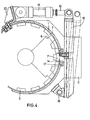
- the chip crusher according to FIG. 1 has a precher housing 1 in which a rotor 2 is drivably mounted.
- the rotor 2 has a pre-breaking arm 3 with a pre-breaking knife 4, the breaking edges of which cooperate with the breaking edges of breaking bars 5, which are fixedly arranged in the breaker housing 1.
- rotor knives 6 of a fine crusher are arranged on the rotor, the breaking edges of which cooperate with the breaking edges of a plurality of stator knives 7 distributed over the circumference in the crusher housing 1.
- the chips to be crushed pass from the hopper 8 into the crusher housing 1, where they are gripped by the pre-crushing arm 3 and broken between the crushing bars 5 and the pre-crushing knife 4 sliding past them at a distance.
- the block 14 is conical and is pressed into a correspondingly conical guide 17 which is placed on the crusher housing 1 and which absorbs the shear forces which act on the stator blades 7 '.
- the stator blades 7 ' are blocked hydraulically by means of the piston-cylinder unit 15. If a coarse part causes a blockage of the rotor, this coarse part can be removed from the crusher chamber by opening the coarse part outlet and reversing the drive of the rotor. The coarse part passes through the coarse part outlet 10 'onto the outlet chute 11. Canach, the stator blades 7' are pressed back into their working position and the chip breaker can resume its normal operation.
- the rotor rotates, for example, at a speed of 60 to 80 rpm.
- the rotor drive is controlled to reverse three to four times. If the rotor has not yet cleared itself, the piston-cylinder drive 15 is given an impulse to open the coarse part outlet 10 'by pulling back the radially movable stator blades 7'. The rotor is then driven reversibly at a speed of 2 to 4 rpm, for example. It has been shown that in most cases the coarse part causing the blocking moves to the open coarse part outlet 10 'and leaves the crusher chamber.
- the chip crusher must be switched off and the cover 12 opened towards the crusher chamber.
- signal generators are attached to this chip breaker, which give an optical and acoustic signal when, after opening the coarse part outlet 10 'and after the motor has been reversed several times, the rotor has not yet cleared itself.
- the housing cover 12 can be opened with a handle and the crusher chamber can be cleared by hand.
- the rotor 2 is fastened to a rotor shaft which is mounted in a frame 13 via a slide bearing and a rolling element bearing.
- the outlet chute 11 is arranged between the crusher housing 1 and the frame 13.
- a co-rotating wiper 30 is arranged on the underside of the rotor and pushes the broken chips out of the outlet space 10 so that they reach the outlet chute 11.
- stator knife 7 ' is arranged to be radially movable.
- This stator knife 7 ' is attached via a block 14 to a rigid lever 18 which is pivotally mounted on the crusher housing 1 about the axis 19 and which can be moved into an open position and a closed position by a piston-cylinder drive 15 via the piston rod 16 . So that the shear forces acting on the stator knife 7 'during chip breaking do not have to be absorbed by the bearing 19, the stator knife 7 1 and the associated block 14 are guided in a guide 17 which is placed on the crusher housing 1.
- the length of the lever 18 corresponds approximately to the diameter of the chip breaker, so that the cylinder-piston drive 15, which is supported against a bracket 20, can be arranged on one side of the chip breaker.
- stator knives 7 1 are arranged to be axially movable, but also the wall 24 of the crusher housing 1 adjoining this stator knife 7 1 and a part 23 of the ceiling 22 of the outlet mouth 21.
- the radially displaceable part 24 of the wall of the crusher housing 1 and the displaceable part 23 of the ceiling 22 of the outlet mouth 21 form with guide walls 26 a slide 25 which is guided radially in a guide housing 27 in relation to the rotor axis 9.
- this guide housing 27 there is the piston-cylinder unit 15, the cylinder of which is rigidly attached to a wall of the housing 27.
Landscapes
- Engineering & Computer Science (AREA)
- Food Science & Technology (AREA)
- Crushing And Pulverization Processes (AREA)
Applications Claiming Priority (2)
| Application Number | Priority Date | Filing Date | Title |
|---|---|---|---|
| DE19838335662U DE8335662U1 (de) | 1983-12-13 | 1983-12-13 | Spaenebrecher |
| DE8335662U | 1983-12-13 |
Publications (2)
| Publication Number | Publication Date |
|---|---|
| EP0146820A1 true EP0146820A1 (fr) | 1985-07-03 |
| EP0146820B1 EP0146820B1 (fr) | 1987-03-04 |
Family
ID=6759787
Family Applications (1)
| Application Number | Title | Priority Date | Filing Date |
|---|---|---|---|
| EP84114517A Expired EP0146820B1 (fr) | 1983-12-13 | 1984-11-30 | Broyeur de copeaux |
Country Status (4)
| Country | Link |
|---|---|
| US (1) | US4903904A (fr) |
| EP (1) | EP0146820B1 (fr) |
| JP (1) | JPS60209264A (fr) |
| DE (2) | DE8335662U1 (fr) |
Cited By (6)
| Publication number | Priority date | Publication date | Assignee | Title |
|---|---|---|---|---|
| US5224656A (en) * | 1991-08-20 | 1993-07-06 | Okawara Mfg. Co., Ltd. | Method of and apparatus for producing a granular product |
| DE4239342A1 (de) * | 1992-11-23 | 1994-05-26 | Breckner Fritz | Zerkleinerungsmaschine zum Mahlen oder Häckseln von industriellen und landwirtschaftlichen Produkten und Abfällen |
| EP0738560A1 (fr) * | 1995-04-18 | 1996-10-23 | Russell Dean Dudley | Appareil de broyage, manipulation, et transport |
| US5631356A (en) * | 1992-04-03 | 1997-05-20 | Gist-Brocades, N.V. | Selective N-acylation of amino alcohols |
| US5769337A (en) * | 1997-01-14 | 1998-06-23 | Abilfida (Chiasso) S.A. | Waste container made of synthetic material with means of reducing the volume of said waste |
| US5785261A (en) * | 1993-09-13 | 1998-07-28 | Lanner; Klaus | Device for reducing the size of steel or metal chips |
Families Citing this family (3)
| Publication number | Priority date | Publication date | Assignee | Title |
|---|---|---|---|---|
| US7748655B2 (en) | 2007-06-15 | 2010-07-06 | Riley Power, Inc. | Crusher block assembly for particulate size reduction system |
| CN112302119B (zh) * | 2020-08-24 | 2022-04-22 | 宁波新冠联机电有限公司 | 一种能打长纤维食物垃圾的处理机 |
| DE102021126898B3 (de) | 2021-10-17 | 2023-03-23 | Thomas Spyra | Zerkleinerer zum Zerkleinern von Spänen |
Citations (1)
| Publication number | Priority date | Publication date | Assignee | Title |
|---|---|---|---|---|
| DE2547980A1 (de) * | 1975-10-27 | 1977-04-28 | Richard Steimel | Spaenebrecher |
Family Cites Families (2)
| Publication number | Priority date | Publication date | Assignee | Title |
|---|---|---|---|---|
| US3703970A (en) * | 1971-02-23 | 1972-11-28 | Benson Ind Ltd | Apparatus for treating waste material |
| JPS5823142A (ja) * | 1981-07-31 | 1983-02-10 | Toshiba Corp | 陰極構体の製造方法 |
-
1983
- 1983-12-13 DE DE19838335662U patent/DE8335662U1/de not_active Expired
-
1984
- 1984-11-30 DE DE8484114517T patent/DE3462437D1/de not_active Expired
- 1984-11-30 EP EP84114517A patent/EP0146820B1/fr not_active Expired
- 1984-12-12 JP JP59260988A patent/JPS60209264A/ja active Pending
-
1989
- 1989-05-15 US US07/352,130 patent/US4903904A/en not_active Expired - Fee Related
Patent Citations (1)
| Publication number | Priority date | Publication date | Assignee | Title |
|---|---|---|---|---|
| DE2547980A1 (de) * | 1975-10-27 | 1977-04-28 | Richard Steimel | Spaenebrecher |
Cited By (6)
| Publication number | Priority date | Publication date | Assignee | Title |
|---|---|---|---|---|
| US5224656A (en) * | 1991-08-20 | 1993-07-06 | Okawara Mfg. Co., Ltd. | Method of and apparatus for producing a granular product |
| US5631356A (en) * | 1992-04-03 | 1997-05-20 | Gist-Brocades, N.V. | Selective N-acylation of amino alcohols |
| DE4239342A1 (de) * | 1992-11-23 | 1994-05-26 | Breckner Fritz | Zerkleinerungsmaschine zum Mahlen oder Häckseln von industriellen und landwirtschaftlichen Produkten und Abfällen |
| US5785261A (en) * | 1993-09-13 | 1998-07-28 | Lanner; Klaus | Device for reducing the size of steel or metal chips |
| EP0738560A1 (fr) * | 1995-04-18 | 1996-10-23 | Russell Dean Dudley | Appareil de broyage, manipulation, et transport |
| US5769337A (en) * | 1997-01-14 | 1998-06-23 | Abilfida (Chiasso) S.A. | Waste container made of synthetic material with means of reducing the volume of said waste |
Also Published As
| Publication number | Publication date |
|---|---|
| EP0146820B1 (fr) | 1987-03-04 |
| JPS60209264A (ja) | 1985-10-21 |
| US4903904A (en) | 1990-02-27 |
| DE3462437D1 (en) | 1987-04-09 |
| DE8335662U1 (de) | 1984-03-08 |
Similar Documents
| Publication | Publication Date | Title |
|---|---|---|
| EP1255612B1 (fr) | Procede et dispositif pour broyer des copeaux | |
| DE2047006C3 (de) | Anlage zum Zerkleinern und teilweisen Trennen von Müll | |
| EP1287878B1 (fr) | Appareil de traitement des materiaux | |
| EP0346661A2 (fr) | Appareil hacheur découpeur | |
| EP1071343B1 (fr) | Dispositif destine a dechiqueter des fruits | |
| EP0146820B1 (fr) | Broyeur de copeaux | |
| DE2547980C2 (fr) | ||
| DE3704300A1 (de) | Hammerbrecher zum brechen harter und weicher materialien | |
| DE4026795A1 (de) | Restholzzerkleinerungsmaschine | |
| DE4423150C1 (de) | Pumpe | |
| DE2731588A1 (de) | Rotorenschere zum zerkleinern von insbesondere sperrigen abfaellen | |
| DE29616319U1 (de) | Walzenbrecher | |
| DE3431658C1 (de) | Ausbildung des Arbeitsspalts bei einer Zerkleinerungsmaschine mit waagerecht angeordnetem Hammerbrecherrotor | |
| DE2026479C3 (de) | Kontinuierlich arbeitende Zentrifuge | |
| DE2925030C2 (de) | Vorrichtung zum Zerkleinern von Abfall wie Drehspähnen o.dgl. | |
| DE102011007960B3 (de) | Pumpe mit einem Schneidwerk | |
| DE3245373A1 (de) | Vorrichtung zum zerkleinern von abfallholz, insbesondere stubben, zu holzschnitzeln | |
| DE10306765A1 (de) | Vorrichtung zur Unbrauchbarmachung von Getränke-Leergut | |
| EP0614700B1 (fr) | Disque d'évacuation pour hachoir-mélangeur | |
| DE1453759C (de) | Kreiselpumpe, insbesonere zur Forderung von Schmutzwasser | |
| DE3045810C2 (de) | Einrichtung und Verfahren zur Regelung eines Holzschleifers | |
| DE219227C (fr) | ||
| DE29621033U1 (de) | Zerkleinerungsmaschine mit Sieb- und Messerwechselvorrichtung | |
| DE10108292A1 (de) | Bohrvorrichtung | |
| DE7534057U (de) | Spaenebrecher |
Legal Events
| Date | Code | Title | Description |
|---|---|---|---|
| PUAI | Public reference made under article 153(3) epc to a published international application that has entered the european phase |
Free format text: ORIGINAL CODE: 0009012 |
|
| AK | Designated contracting states |
Designated state(s): DE FR GB IT |
|
| 17P | Request for examination filed |
Effective date: 19851204 |
|
| 17Q | First examination report despatched |
Effective date: 19860610 |
|
| GRAA | (expected) grant |
Free format text: ORIGINAL CODE: 0009210 |
|
| AK | Designated contracting states |
Kind code of ref document: B1 Designated state(s): DE FR GB IT |
|
| ITF | It: translation for a ep patent filed | ||
| REF | Corresponds to: |
Ref document number: 3462437 Country of ref document: DE Date of ref document: 19870409 |
|
| ET | Fr: translation filed | ||
| PLBE | No opposition filed within time limit |
Free format text: ORIGINAL CODE: 0009261 |
|
| STAA | Information on the status of an ep patent application or granted ep patent |
Free format text: STATUS: NO OPPOSITION FILED WITHIN TIME LIMIT |
|
| 26N | No opposition filed | ||
| ITTA | It: last paid annual fee | ||
| PGFP | Annual fee paid to national office [announced via postgrant information from national office to epo] |
Ref country code: FR Payment date: 19951017 Year of fee payment: 12 |
|
| PGFP | Annual fee paid to national office [announced via postgrant information from national office to epo] |
Ref country code: GB Payment date: 19951113 Year of fee payment: 12 |
|
| PGFP | Annual fee paid to national office [announced via postgrant information from national office to epo] |
Ref country code: DE Payment date: 19960123 Year of fee payment: 12 |
|
| PG25 | Lapsed in a contracting state [announced via postgrant information from national office to epo] |
Ref country code: GB Effective date: 19961130 |
|
| GBPC | Gb: european patent ceased through non-payment of renewal fee |
Effective date: 19961130 |
|
| PG25 | Lapsed in a contracting state [announced via postgrant information from national office to epo] |
Ref country code: FR Effective date: 19970731 |
|
| PG25 | Lapsed in a contracting state [announced via postgrant information from national office to epo] |
Ref country code: DE Effective date: 19970801 |
|
| REG | Reference to a national code |
Ref country code: FR Ref legal event code: ST |