EP0146848A2 - Dispositif pour le maintien de skis - Google Patents
Dispositif pour le maintien de skis Download PDFInfo
- Publication number
- EP0146848A2 EP0146848A2 EP84114855A EP84114855A EP0146848A2 EP 0146848 A2 EP0146848 A2 EP 0146848A2 EP 84114855 A EP84114855 A EP 84114855A EP 84114855 A EP84114855 A EP 84114855A EP 0146848 A2 EP0146848 A2 EP 0146848A2
- Authority
- EP
- European Patent Office
- Prior art keywords
- ski
- pressure ring
- gripper
- skis
- support
- Prior art date
- Legal status (The legal status is an assumption and is not a legal conclusion. Google has not performed a legal analysis and makes no representation as to the accuracy of the status listed.)
- Granted
Links
Images

Classifications
-
- B—PERFORMING OPERATIONS; TRANSPORTING
- B60—VEHICLES IN GENERAL
- B60R—VEHICLES, VEHICLE FITTINGS, OR VEHICLE PARTS, NOT OTHERWISE PROVIDED FOR
- B60R9/00—Supplementary fittings on vehicle exterior for carrying loads, e.g. luggage, sports gear or the like
- B60R9/08—Supplementary fittings on vehicle exterior for carrying loads, e.g. luggage, sports gear or the like specially adapted for sports gear
- B60R9/12—Supplementary fittings on vehicle exterior for carrying loads, e.g. luggage, sports gear or the like specially adapted for sports gear for skis
Definitions
- the invention relates to a device for holding skis on roof racks of motor vehicles with a one-sided open ski gripper to be arranged on the roof racks, in which the inserted skis are held by a pressure piece which acts elastically transversely to the direction of insertion of the skis.
- the ski gripper In a device of this type (DE-GM 78 05 616) the ski gripper consists of an essentially U-shaped body, the two legs forming the support jaws and receiving the skis between them. One of these legs or jaws is articulated on the base body and loaded by a coil spring in the direction of the other jaws, so that it forms the pressure piece which presses the inserted ski against the opposite support jaws. If no skis are inserted, the support jaw designed as a pressure piece is in contact with its upper end in the vicinity of the opposite support jaw, which makes it more difficult to insert the ski insofar as the pressure piece first has to be pivoted back against the action of the spring by hand to provide a sufficiently large insertion opening.
- the support jaw designed as a pressure piece essentially only presses against the upper edge of the ski, which leads to a relatively small contact area between this movable support jaw and the ski.
- this ski is not sufficiently held in its longitudinal direction, which is necessary with the high acceleration forces that arise in an emergency braking occurs. It is therefore always necessary to connect the two inserted skis with each other, so too. the ski, which rests on the movable support jaw, is adequately secured in the longitudinal direction after only the opposite rigid support jaw has a large contact surface and can therefore transmit large holding forces when accelerated.
- the formation of this ski gripper is also disadvantageous for manufacturing reasons, because the gripper base body consists of two parts which are connected to one another by a pivot axis, a helical spring also having to be arranged on top of that.
- the object of the invention is to provide a structurally simple ski gripper which, with an appealing external design, enables easy operation both when inserting and removing the skis, large holding forces, in particular in the longitudinal direction of the ski, and a wide clamping range.
- the base body of the ski gripper consists of a single part, which is for example made of plastic by injection molding and thus forms a simple part.
- a spring must be provided for loading the movable jaw part.
- the pressure ring When the skis are pushed into the ski gripper, which is open on one side, the pressure ring, at least one of which can be provided on each support jaw, is pushed outwards, preferably escaping into a recess in the support jaw which the support jaw has for receiving the pressure ring.
- two pressure rings are assigned to a support jaw, these can be arranged one below the other or in alignment. In the latter embodiment, the pressure rings can also be attached to an outer side of the support jaw.
- the main axis running symmetrically between the articulation points of the pressure ring and through the center of the ring assumes an acute angle with the direction of insertion, the insertion of the skis is thereby facilitated and the holding force against pulling out is increased.
- a pressure ring can be provided on a support jaw and at least one rotatably mounted support body on the opposite support jaw, against which the ski rests in the holding position.
- This support body can be designed as a roller with a circular cross section or with a polygonal cross section, which makes it easier to insert the ski into the gripper. Since the support body can have a length that corresponds almost to the thickness of the ski gripper, seen in the longitudinal direction of the ski, a large contact surface of the ski on the support body can be achieved.
- the holding force in the longitudinal direction can be increased thereby be that in a further embodiment of the invention, the support body consists of an elastic material with a high coefficient of friction, preferably rubber. Since the support body is rotatably mounted, this choice of material does not make it difficult to insert the ski, but the holding force in the longitudinal direction of the ski, ie in the longitudinal direction of the support body, is significantly increased.
- a movably arranged on the support jaw can be arranged over the pressure ring the pressing ring, designed in the manner of a switch, can be provided for the ski.
- the ski is guided along this insertion aid during insertion into the gripper, at least during the first deformation phase, and is not displaced with respect to the pressure ring, so that insertion is made easier especially with a pressure ring with a high coefficient of friction.
- the insertion aid designed in the manner of a switch can be arranged relatively obliquely, so that the insertion of the ski is facilitated.
- the pressure ring is pushed out of its initial position, in which it largely fills the receiving area in the ski gripper, by this insertion aid when the ski is pressed against the insertion aid.
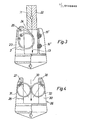
- the exemplary embodiment of a ski gripper shown in FIGS. 1 and 2 has a basic body 1 and a pressure ring 2 as essential components.
- the base body 1 is U-shaped and has two support jaws 3, 4, which are made in one piece with a base part 5.
- the base part has a continuous bore 6, which serves to receive a cross member of a roof rack. 7 with a bore is designated, into which a clamping screw is inserted in order to clamp the base body 1 on a supporting part, not shown, or a cross member of a roof rack.
- the pressure ring 2 is designed as an open ring and has fastening eyes 8, 9 at its ends through which rivets 10 and 11 serving as bearing axles pass, which fix the pressure ring 2 on the support jaw 3 of the base body 1 in such a way that the ends formed as eyes 8 , 9 are held pivotably.
- the pressure ring 2 is designed in the manner of a circlip. Its symmetrical to the articulation points 10.11 through the center the main axis of the pressure ring 2 is denoted by 12 and forms an acute angle with the insertion direction indicated by the arrow 13 for the skis.
- the pressure ring 2 starting from its free ends, slopes diagonally downward into the receiving area 14 of the base body 1 and is so close to the opposite support jaw 4 that the introduction of a single ski causes deformation of the pressure ring and thus clamping of this ski would cause.
- support bodies 15 and 16 in the support jaws 4 opposite the pressure ring which are designed as rollers and around horizontal axes of rotation 17, 18 are rotatably mounted.
- These support bodies have a circular cross section J and are expediently made of a material with a high coefficient of friction, preferably rubber, so that the ski remains securely held in the ski gripper in its longitudinal direction in the event of strong decelerations.
- the support bodies 15, 16 are let into the support jaw 4 to such an extent that they protrude only slightly beyond the inner surface 19 of the support jaw 4.
- a nose 20 protruding into the receiving area 14 is formed, which is used to secure inserted skis, as can be seen in particular from the illustration in FIG. 2.
- FIG. 2 shows the state of the ski gripper with inserted skis 21, 22, caused by the deformed pressure ring 2 are pressed against the support body 15, 16, the ski 22 adjacent to the support jaw 4 being partially covered by the nose 20, so that this ski is prevented from falling out due to shaking movements.
- This illustration in FIG. 2 shows that the pressure ring 2 is deformed by the inserted skis within a recess 23 in which it is received within the support jaw.
- the pressure ring When the pressure ring is deformed, the ends of the pressure ring move about the pivot axes 10 and 11, the ring being converted from its circular shape into a pear shape. Since the pressure ring consists of a resilient material, for example steel or a special plastic, sufficient spring energy is stored by this deformation, which is sufficient to hold the inserted skis 21 and 22 in the gripper body 1.
- Both the pressure ring 2 and the support body 15 and 16 are seen in the longitudinal direction of the ski with such a large dimension that a sufficiently high static friction occurs, which prevents a shift of the ski in the longitudinal direction even with large braking decelerations.
- the embodiment according to FIG. 3 shows two modifications compared to the embodiment according to FIGS. 1 and 2.
- the first modification consists of a different embodiment of the support body, namely support bodies 15 'and 16' are provided in this embodiment, which have a hexagonal cross section , which results in larger contact surfaces between the support body and the inserted ski.
- the second modification is that above the pressure ring 2, a pivotally mounted insertion Help 24 is provided, which is mounted about an axis 25 within the recess 23 and is designed in the manner of a switch.
- This insertion aid rests on the pressure ring 2 and is pressed down when the skis 21, 22 are inserted. The end of the insertion aid resting on the pressure ring then deforms the pressure ring. Since the insertion aid 24 is strongly inclined with respect to the insertion direction 13, ie forms a relatively small angle with this insertion direction, the insertion of the skis is facilitated by this incline.
- FIG. 4 Another embodiment of the ski gripper is shown in FIG. 4, which in principle has the same base body that is designated 26 in this FIG.
- This base body is provided with two support jaws 27 and 28, which are provided with openings 29 and 30 for receiving a pressure ring 31 and 32, respectively.
- inserted skis are loaded from both sides by pressure rings. This makes it possible to hold even a very thin ski securely, as the pressure rings 31 and 32 completely fill the receiving area 33 of the gripper.
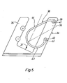
- FIG. 5 shows a base body of the gripper, which is denoted overall by 34 and has support jaws 35 and 36 which are inclined with respect to the horizontal, so that inserted skis do not stand upright, as in the previously described embodiments, but are inclined in the gripper, in which they are inserted at an angle, as indicated by arrow 37, which indicates the direction of insertion.
- Pressure ring 38 is provided, the free ends 39 and 40 of which are movably mounted about axes 41 and 42.
- These pressure rings differ from the circular shape and each have a lower, almost semicircular section 43 and an upper, substantially rectilinear section 44, which serves as an insertion bevel.
Landscapes
- Engineering & Computer Science (AREA)
- Mechanical Engineering (AREA)
- Fittings On The Vehicle Exterior For Carrying Loads, And Devices For Holding Or Mounting Articles (AREA)
- Grinding Of Cylindrical And Plane Surfaces (AREA)
- Facsimile Scanning Arrangements (AREA)
Priority Applications (1)
| Application Number | Priority Date | Filing Date | Title |
|---|---|---|---|
| AT84114855T ATE36995T1 (de) | 1983-12-09 | 1984-12-06 | Vorrichtung zum halten von ski. |
Applications Claiming Priority (2)
| Application Number | Priority Date | Filing Date | Title |
|---|---|---|---|
| DE19833344611 DE3344611A1 (de) | 1983-12-09 | 1983-12-09 | Vorrichtung zum halten von ski |
| DE3344611 | 1983-12-09 |
Publications (3)
| Publication Number | Publication Date |
|---|---|
| EP0146848A2 true EP0146848A2 (fr) | 1985-07-03 |
| EP0146848A3 EP0146848A3 (en) | 1985-08-07 |
| EP0146848B1 EP0146848B1 (fr) | 1988-09-07 |
Family
ID=6216530
Family Applications (1)
| Application Number | Title | Priority Date | Filing Date |
|---|---|---|---|
| EP84114855A Expired EP0146848B1 (fr) | 1983-12-09 | 1984-12-06 | Dispositif pour le maintien de skis |
Country Status (3)
| Country | Link |
|---|---|
| EP (1) | EP0146848B1 (fr) |
| AT (1) | ATE36995T1 (fr) |
| DE (1) | DE3344611A1 (fr) |
Families Citing this family (5)
| Publication number | Priority date | Publication date | Assignee | Title |
|---|---|---|---|---|
| JPS63503285A (ja) * | 1986-05-20 | 1988-12-02 | スマート,ピーター・アイノン | スキー運搬装置 |
| SE9000349D0 (sv) * | 1990-02-01 | 1990-02-01 | Thule Ind Ab | Anordning foer parvis transport av laangstraeckta foeremaal |
| US5054673A (en) * | 1990-03-19 | 1991-10-08 | Rola Roof Racks International, Inc. | Vehicle ski carrier system |
| DE10104513C1 (de) * | 2001-01-31 | 2002-07-11 | Montana Sport Internat Ag Stan | Halterung, insbesondere Skihalterung |
| US12420720B2 (en) * | 2021-02-26 | 2025-09-23 | Bombardier Recreational Products Inc. | Accessory rack assembly and accessory rack kit |
Family Cites Families (4)
| Publication number | Priority date | Publication date | Assignee | Title |
|---|---|---|---|---|
| DE1678268A1 (de) * | 1968-02-09 | 1971-12-09 | Alfred Kinshofer | Verfahren und Vorrichtung zum Aufbewahren von Skiern |
| FR2395863A1 (fr) * | 1977-06-28 | 1979-01-26 | Prealpina Sas | Porte-skis avec fermeture de surete |
| DE7805616U1 (de) * | 1978-02-24 | 1978-06-08 | Neurieder, Manfred, 8950 Kaufbeuren | Skiträger für Kraftfahrzeuge |
| DE2835734C2 (de) * | 1978-08-16 | 1985-05-02 | Geze Gmbh, 7250 Leonberg | Skihaltevorichtung |
-
1983
- 1983-12-09 DE DE19833344611 patent/DE3344611A1/de active Granted
-
1984
- 1984-12-06 EP EP84114855A patent/EP0146848B1/fr not_active Expired
- 1984-12-06 AT AT84114855T patent/ATE36995T1/de active
Also Published As
| Publication number | Publication date |
|---|---|
| ATE36995T1 (de) | 1988-09-15 |
| DE3344611C2 (fr) | 1989-03-02 |
| DE3344611A1 (de) | 1985-06-27 |
| EP0146848B1 (fr) | 1988-09-07 |
| EP0146848A3 (en) | 1985-08-07 |
Similar Documents
| Publication | Publication Date | Title |
|---|---|---|
| DE69912916T2 (de) | Aufbau einer Befestigung für Dachträger | |
| DE2942806C2 (de) | Skibindung, insbesondere Langlaufskibindung | |
| DE3888364T3 (de) | Eine lasttragende vorrichtung. | |
| DE3924915C2 (de) | Langlaufskibindung der Scharnierbauart | |
| EP0516598B1 (fr) | Pince avec introduction avant et côté facultative | |
| EP0557735A1 (fr) | Dispositif de fixation d'une chaussure sur une pédale de bicyclette | |
| DE2944748A1 (de) | Halteclip zur loesbaren befestigung von funktionselementen auf einer traegerplatte mittels gewindebolzen | |
| DE2732423A1 (de) | Formvorrichtung | |
| DE2854708A1 (de) | Abgabeverschluss | |
| DE3243598A1 (de) | Traeger fuer endlos-schleifhuelse | |
| DE3128169C2 (de) | Abnehmbarer Tragegriff | |
| DE3813342C2 (de) | Klemmeinrichtung | |
| DE3920454C2 (fr) | ||
| DE2235243B2 (de) | Ausloesender fersenbacken fuer skibindungen | |
| EP0146848B1 (fr) | Dispositif pour le maintien de skis | |
| EP0070400B1 (fr) | Etau | |
| DE9405680U1 (de) | Geschmiedete Anschlußklemme zum lösbaren Befestigen eines Stromkabels an einem konischen Pol eines Akkumulators | |
| DE2659368C2 (de) | Zangenartiges Werkzeug zum Befestigen einer Zuglasche an einem Reißverschlußschieber | |
| DE4021229A1 (de) | Sicherheitsskibindung | |
| CH549356A (de) | Spannhebelverschluss fuer skischuhe, insbesondere fuer plastic-skischuhe. | |
| DE3704751A1 (de) | Lager fuer sonnenblendenkoerper, insbesondere fuer fahrzeugsonnenblenden | |
| DE3822325C1 (fr) | ||
| DE69100009T2 (de) | Wagenheber. | |
| DE2052385C3 (de) | Klemmvorrichtung für Seile, Leinen o.dgl | |
| DE2058464A1 (de) | Loesbares Spann- und Halteglied fuer Seile |
Legal Events
| Date | Code | Title | Description |
|---|---|---|---|
| PUAI | Public reference made under article 153(3) epc to a published international application that has entered the european phase |
Free format text: ORIGINAL CODE: 0009012 |
|
| PUAL | Search report despatched |
Free format text: ORIGINAL CODE: 0009013 |
|
| AK | Designated contracting states |
Designated state(s): AT CH FR IT LI SE |
|
| AK | Designated contracting states |
Designated state(s): AT CH FR IT LI SE |
|
| 17P | Request for examination filed |
Effective date: 19851223 |
|
| 17Q | First examination report despatched |
Effective date: 19861203 |
|
| D17Q | First examination report despatched (deleted) | ||
| GRAA | (expected) grant |
Free format text: ORIGINAL CODE: 0009210 |
|
| AK | Designated contracting states |
Kind code of ref document: B1 Designated state(s): AT CH FR IT LI SE |
|
| PG25 | Lapsed in a contracting state [announced via postgrant information from national office to epo] |
Ref country code: SE Effective date: 19880907 |
|
| REF | Corresponds to: |
Ref document number: 36995 Country of ref document: AT Date of ref document: 19880915 Kind code of ref document: T |
|
| ET | Fr: translation filed | ||
| ITF | It: translation for a ep patent filed | ||
| PLBE | No opposition filed within time limit |
Free format text: ORIGINAL CODE: 0009261 |
|
| STAA | Information on the status of an ep patent application or granted ep patent |
Free format text: STATUS: NO OPPOSITION FILED WITHIN TIME LIMIT |
|
| 26N | No opposition filed | ||
| ITTA | It: last paid annual fee | ||
| PGFP | Annual fee paid to national office [announced via postgrant information from national office to epo] |
Ref country code: CH Payment date: 19931110 Year of fee payment: 10 |
|
| PGFP | Annual fee paid to national office [announced via postgrant information from national office to epo] |
Ref country code: FR Payment date: 19931126 Year of fee payment: 10 |
|
| PGFP | Annual fee paid to national office [announced via postgrant information from national office to epo] |
Ref country code: AT Payment date: 19931230 Year of fee payment: 10 |
|
| PG25 | Lapsed in a contracting state [announced via postgrant information from national office to epo] |
Ref country code: AT Effective date: 19941206 |
|
| PG25 | Lapsed in a contracting state [announced via postgrant information from national office to epo] |
Ref country code: LI Effective date: 19941231 Ref country code: CH Effective date: 19941231 |
|
| PG25 | Lapsed in a contracting state [announced via postgrant information from national office to epo] |
Ref country code: FR Effective date: 19950831 |
|
| REG | Reference to a national code |
Ref country code: CH Ref legal event code: PL |
|
| REG | Reference to a national code |
Ref country code: FR Ref legal event code: ST |