EP0146888A2 - Outside rear view mirror - Google Patents
Outside rear view mirror Download PDFInfo
- Publication number
- EP0146888A2 EP0146888A2 EP84115371A EP84115371A EP0146888A2 EP 0146888 A2 EP0146888 A2 EP 0146888A2 EP 84115371 A EP84115371 A EP 84115371A EP 84115371 A EP84115371 A EP 84115371A EP 0146888 A2 EP0146888 A2 EP 0146888A2
- Authority
- EP
- European Patent Office
- Prior art keywords
- mirror housing
- rear view
- outside rear
- spindle member
- base
- Prior art date
- Legal status (The legal status is an assumption and is not a legal conclusion. Google has not performed a legal analysis and makes no representation as to the accuracy of the status listed.)
- Granted
Links
Images











Classifications
-
- B—PERFORMING OPERATIONS; TRANSPORTING
- B60—VEHICLES IN GENERAL
- B60R—VEHICLES, VEHICLE FITTINGS, OR VEHICLE PARTS, NOT OTHERWISE PROVIDED FOR
- B60R1/00—Optical viewing arrangements; Real-time viewing arrangements for drivers or passengers using optical image capturing systems, e.g. cameras or video systems specially adapted for use in or on vehicles
- B60R1/02—Rear-view mirror arrangements
- B60R1/06—Rear-view mirror arrangements mounted on vehicle exterior
- B60R1/062—Rear-view mirror arrangements mounted on vehicle exterior with remote control for adjusting position
- B60R1/07—Rear-view mirror arrangements mounted on vehicle exterior with remote control for adjusting position by electrically powered actuators
- B60R1/074—Rear-view mirror arrangements mounted on vehicle exterior with remote control for adjusting position by electrically powered actuators for retracting the mirror arrangements to a non-use position alongside the vehicle
-
- Y—GENERAL TAGGING OF NEW TECHNOLOGICAL DEVELOPMENTS; GENERAL TAGGING OF CROSS-SECTIONAL TECHNOLOGIES SPANNING OVER SEVERAL SECTIONS OF THE IPC; TECHNICAL SUBJECTS COVERED BY FORMER USPC CROSS-REFERENCE ART COLLECTIONS [XRACs] AND DIGESTS
- Y10—TECHNICAL SUBJECTS COVERED BY FORMER USPC
- Y10S—TECHNICAL SUBJECTS COVERED BY FORMER USPC CROSS-REFERENCE ART COLLECTIONS [XRACs] AND DIGESTS
- Y10S248/00—Supports
- Y10S248/90—Movable or disengageable on impact or overload
Definitions
- the present invention relates to an outside rear view mirror for cars provided with a drive transmitting mecha- nism for electrically swinging its-mirror housing relative to the base.
- Figs. 1 and 2 of this patent show the conventional outside rear view mirror, in which Fig. 1 is a vertically-sectioned view" thereof and Fig. 2 a partially-sectioned view thereof.
- the mirror housing (3) is swingably attached to the body (6) by means of a plate-like arm (17) and a screw (15) in the case of this conventional outside rear view mirror (4).
- the plate-like arm (17) is engaged with the boss of the mirror housing (3) by means of plural projections.
- the mirror housing (3), plate-like arm (17) and body (7) are held, pressed against one another, by a spring (38).
- the mirror housing (3) is displaced forward or backward, taking the screw (15) as its center, when the handle (21) is moved forward or backward in Fig. 1.
- the handle (2 1 ) is rotated, taking the center axis of the plate-like arm (17) as its center, the mirror housing (3) is displaced up and down.
- the mirror housing (3) When excessive load is added to the mirror housing (3), the mirror housing (3) is released from the plate-like arm (17) and swung toward the door (2).
- the above-described conventional outside rear view mirror (4) is most suitable for use as a device whose range of vision can be adjusted by the handle (21).
- forward or backward displacement of the mirror housing (3) is determined by the amount of handle (21) operation carried out in the car room.
- This amount of handle (21) operation is limitted to a range necessary to adjust the field of vision allowed by the mirror (4).
- the mirror housing (3) which is projected outside the car body is swung over the range of adjusting the field of vision and displaced to contact with the car body at the time of transporting or garaging the car, the mirror housing must be forcedly swung against the spring (28) and released from the boss projections (16). Namely, the mirror housing must be brought under such state-that, impact has been artificially added to the mirror housing (3).
- the object of the present invention is to provide and outside rear view mirror which can be remotely operated in the car room to swing the mirror housing relative to the base and displace it toward the car body.
- an outside rear view mirror comprising a base to which a mirror housing, which adjustably holds a mirror, is swingably attached through a spindle member, a drive transmitting mechanism for remotely operating the mirror housing to automatically swing it in relation to the base, and a buffer mechanism arranged between the mirror housing and the base.
- Figs. 3 through 17 show a first embodiment of the present invention.
- an outside rear view mirror 1 comprises a mirror housing 10 for adjustably holding a mirror 50 in the opening thereof, a base 20 to which the mirror housing 10 is swingably attached through a spindle member 40, a drive transmitting mechanism 30 for swinging the mirror housing 10 relative to the base 20, and a buffer mechanism 60 located between the mirror housing 10 and the spindle member.
- the outside rear view mirror 1 is attached to a car body 90 in such a way that is is projected only by distance l the car body 90.
- the mirror housing 10 is of the rectangular type, having longer horizontal sides, and formed different from the base 20.
- the mirror 50 is held in the opening of the mirror housing 10 to adjust the field of vision.
- the mirror housing 10 is swingably supported by the base 20 through the spindle member, and a buffer mechanism 60 which comprises springs 61 and 62 arranged between the mirror housing 10 and the base 20 and between the base 20 and the spindle member 40, respectively, serves to buffer such impact that is larger than a certain load.
- This impact buffering can be attained in such a way that the mirror housing 10 and spindle member 40 are swung round the base 20 against the springs 61 and 62 when the impact is added from outside to the mirror housing 10 of the outside rear view mirror which comprises the mirror housing 10,.base 20 and spindle member 40 urged by the springs 61 and 62.
- the mirror housing 10 is swung round the spindle member 40 by remotely operating the drive transmitting mechanism 30 in the car room except the case where it is forcedly swung by the strong impact as described above.
- a base attaching portion 13 which is recessed inward a bottom wall 11 of the mirror housing 10 is formed at that portion of the bottom wall 11 of the mirror housing 10 which is located on the side of the base 20.
- a side wall 12 of the mirror housing 10 is arranged to have a curve portion.
- a mount 14 is projected from the base attaching portion 13 inward the mirror housing 10.
- the spindel member 40 passing through a through-hole 15 which is to formed in the mount 14.
- the mount 14 includes a tapered circumference 15c, having an upper small-diameter portion 15a and a lower large-diameter portion 15b, and a ring-shaped recess 15d around the large-diameter portion 15b.
- the base 20 has a vertical wall 27 provided with a curve portion which corresponds to the side wall 12 of the mirror housing 10, and a support 21 which extends hofizontally from the vertical wall 27 toward the mirror housing 10.
- a conical bearing 22 is projected from the support 21.
- a spring attaching portion 24 is formed on the underside of the bearing 22 and a-through-hole 23 through which a cylindrical shaft 41 of the spindle member 40 passes is formed in the bearing 22, extending from the bottom of the spring attaching portion 24 to the upper side of the bearing 22.
- Three projections 26 are formed on the circumference of the bearing 22 of the base 20, each separated from the others at an angle of 120°.
- the spindle member 40 includes a cylindrical shaft 41 and a conical ring-shaped wall 42 which is enlarged downward and which is integrally formed at the center portion of the cylindrical shaft 41.
- a ring-shaped recess 44 whose outer wall is tapered or enlarged downward is formed between the cylindrical shaft 41 and the conical ring-shaped wall 42.
- Engagement recesses 48 are formed, each separated from the others at an angle of 120°, on the lower and face of the ring-shaped wall 42. These engagement recesses 48 are engaged with the projections 26 on the base 20.
- a spur gear attaching portion 45 is formed on the cylindrical shaft 41 and a spur gear 35 located on the fixed side of the transmitting mechanism 30 is attached is formed on the cylindrical shaft 41.
- the spur gear attaching portion 45 has a D-shaped section and located adjacent of the top of the ring-shaped wall 42. Formed on the upper and lower ends of the cylindrical shaft 41 are recesses 46 and 47 into which clips 65 and 66 are fitted to hold the springs 61 and 62 of the buffer mechanism 60.
- a cord 70 which is connected to a drive motor 31 for the drive transmitting mechanism 30 is inserted through a hollow portion 49 of the cylindrical shaft 41.
- the drive transmitting mechanism 30 comprises the spur gear 35 which is located on the fixed side and which is fixed to the portion 45 of the cylindrical shaft 41, another spur gear 34 which is engaged with the spur gear 35, fixed to a motor shaft 33 of the drive motor 31, and located on the movable side, the drive motor for rotating the spur gear 34, and a speed reducer 32.
- the buffer mechanism 60 comprises the spring 61 which is compressed between the engagement recess 46 located on the upper end side of the cylindrical shaft 41 and the upper face of a cover 80 by means of two washers 63 and a clip 65, and the spring 62 which is compressed in the spring attaching portion 24 of the base 20 by means of the clip 66 and two washers 64, said clip 66 being fitted into the engagement recess 47 located on the lower end side of the cylindrical shaft 41.
- the cover 80 serves to seal the two spur gears 34 and 35 of the drive transmitting mechanism 30, and includes a through-hole 84 for the cylindrical shaft 41, a through-hole 85 for the motor shaft 31, and a bearing 82 for the spur gear 34.
- the mirror housing, base, spindle member drive transmitting mechanism and cover are assembled one another as follows.
- the spindle member 40 is attached to the bearing 2 2 projected from the support 21 of the base 20.
- the cylindrical shaft 41 of the spindle member 40 is passed through the through-hole 23-in the bearing 22 of the base 20 and the spring attaching protion 24 and projected below the base 20 under this state.
- Tapered ring-shaped recess 44 between the cylindrical shaft 41 of the spindle member 40 and the ring-shaped wall 42 is fitted onto the bearing 22 and their tapered faces are contacted each other.
- the engagement recesses 48 on the bottom face of the flange 43 of the ring-shaped wall 42 are fitted onto the projections 26 on the circumference of the bearing 22 at the support 21 of the base 20 to thereby set the spindle member 40 at a desired position.
- the mirror housing 10 is then attached to the spindle member 40 which has been set to the base 20.
- the through-hole 15 in the mount 14 of the mirror housing 10 is fitted onto the ring-shaped wall 42 of the spindle member 40 under this state. At this time, both of the ring-shaped wall 42 and through-hole 15 are contacted with each other and the upper end portion of the cylindrical shaft 41 is projected inward the mirror housing 10.
- the spur gear 35 located on the fixed side.
- a shaft 35a of the spur gear 35 is fitted into the through-hole 15 and both of the spur gear 35 and spur gear attaching portion 45 of the cylindrical shaft 41 are fitted each other not to rotate relative to the other.
- the spur gear 34 located on the movable side is set on the mount 14 to engage the spur gear 35 and these are sealed by the; cover 80.
- the cylindrical shaft 41 is projected through the through-hole 84 in the cover inward the mirror housing 10, and the motor shaft 33 of the drive motor 31 on the top of the cover 80 is passed through the through-hole 85, with the speed reducer 32 interposed, into the hollow portion 81 in the cover 80 to fit into the spur gear 34.
- a shaft 34a of this spur gear 34 is supported by the bearing 82 of the cover 80.
- the cover 80 is fixed on.the mount 14 by means of a screw 83 (See fig. 5).
- the drive motor 31 and speed reducer 32 are attached to the top of the cover 80, and the cord 70 is introduced outside through the hollow portion 49 in the cylindrical shaft 41.
- the buffer mechanism 60 is attached to the assembly thus obtained. More specifically, the spring 61 which is - interposed between the two washers 63 is fitted onto the cylin drical shaft 41 projected from the top of the cover 80 and compressed and fixed by the clip 65 fitted onto the engagement recess 46. The spring 62 which is interposed between the two washers 64 is similarly attached to the lower end of the cylindrical shaft 41 projected at the spring attaching portion 24 of the base 20 and it is compressed and fixed by the clip 66 fitted onto the engagement recess 47.
- the tapered faces 25, 44a, 42a and 15c of the bearing 22 of the base 20, of the ring-shaped wall 42 of the spindle member 40, of the ring-shaped wall 42, and of the through-hole 15 in the mount 14 of the mirror housing 10 are forcedly contacted with one acnother by the springs 61 and 62, thereby causing the projections 26 to be forcedly engaged with the engagement recesses 48.
- the drive motor 31 is rotated and its rotation is transmitted to the spur gear 34 through the speed reducer 32. Since the spur gear 34 is engaged with the spur gear 35 located on the fixed side, the rotation is transmitted in a direction in which the spur gear 35 is rotated. However, the spur gear 35 located on the fixed side is unswingably attached to the cylindrical shaft 41 of the spindle member 40 and this spindle member 40 is limited in its swinging movement by the two springs 61 and 62 of the buffer mechanism 60 and by the engagement between the projections 26 and the engagement recesses 48 in such a way that it is not swung by any load- smaller than the certain load.
- the spur gear 35 is fixed and the another spur gear 34 moves around the spur gear 35 and on its axis.
- the mirror housing 10 which fixes the spur gear 34 thus moves round the cylindrical shaft 41 and slides on the tapered face 44a of the spindle member 40 to swing backward.
- the drive motor 31 is reversly rotated to reversely rotate the spur gear 34.
- Fig. 9 shows a case where the mirror housing 10 is swung backward by the external force P added thereto from front.
- Fig. 10 shows a case where the mirror housing 10 is swung forward by the external force P added thereto from back. As described above referring to Fig. 9,the mirror housing 10 and spindle member 40 are simultaneously slid and swung forward on the tapered face of the bearing 22 of the base 20, thereby buffering the impact of the external force P.
- the mirror housing When arranged as described above, the mirror housing can be easily swung by remote operation in the car room to become parallel to the outside of the car body at the time of transporting the car to which the outside rear view mirrors . are attached or garaging it, thereby enabling car transportation space to be made smaller and preventing the mirror housings from becoming obstacles at the time of garaging the car.
- the buffer mechanism is arranged between the mirror housing and the base. Therefore, the mirror housing is swung to buffer impact even when the impact is added to the mirror housing, thereby proventing reducing the damage of human beings and the outside rear view mirror 1.
- the mirror housing 10, base 20 and spindle member 40 are slidably contacted with one another at their conical tapered faces. Therefore, the outside rear view mirror 1 is excellent in stability and it hardly happens that the field of vision is made worse by the vibration of the mirror 50.
- Figs. 18 through 23 show a second embodiment of the present invention, which is fundamentally similar to the first embodiment.
- mirror housing, base, cover and buffer mechanism are almost same as those in the first embodiment, they are represented by same reference numerals, but parts which are different from those in the first embodiment will be denoted by different reference numerals and described below.
- the through-hole 23 in the bearing 22 of the base 20 is provided with a pair of key grooves 123.
- the spindle member 140 has a cylindrical shaft 1 4 1 .
- Two projection 142 and a conical slide-contact wall 144 spaced therefrom are farmed integrally to the cylindrical shaft 141.
- -A portion between the projections 142 and the conical slide- contact wall 144 is a spur gear attaching portion for attaching a spur gear 135.
- the conical slide-contact wall 144 is enlarged upward and the spur gear 135 being located on the fixed side.
- the drive transmitting mechanism 30 is substantially same in arrangement as in the first embodiment, but a tapered recess 36 is formed on the upper poetion of the through-hole 37, of the spur gear 135 located on the fixed side. Further, a pair of grooves 137 are formed on the inner wall of the through-hole 37. The projections 142 on the cylindrical shaft 141 are passed through the grooves 137, respectively.
- the through-hole 15 of the mirror housing 10 is fitted onto the bearing 22 of the base 20 to locate the mirror housing 10 on the base 20, the spur gear 135 is positioned on bearing 22, and the cylindrical shaft 141 of the spindle member 40 is then inserted into the assembly from above.
- the projections 142 on the cylindrical shaft 141 are passed through the paired grooves 137 which are formed on the inner face of through-hole 37 of the spur gear 135 located on the fixed side, and they are fitted, movable up and down, into the key grooves in the bearing 22 of the base 20.
- the spur gear 34 located on the movable side is then engaged with the spur gear 135 located on the fixed side and the cover 80 seals these spur gears of the drive transmitting mechanism 30.
- the mirror housing 10 is pressed against the base 20, using the springs 6 1 , 62, lips 65, 66 and washers 63, 64 which form the buffer mechanism 60.
- the drive motor 31 is rotated, and its rotation is reduced by the speed reducer 32 and transmitted to the spur gear 34.
- the spur gear 34 Since the spur gear 34 is engaged with the spur gear 135 located on the fixed side, the rotation is transmitted to the spur gear 135 to rotate it, but the spur gear 135 located on the fixed side is slide-contacted with the tapered face between the recess 36 and the slide-contact wall 144 on the cylindrical shaft 141 and compressive force is applied to the tapered slide-contact face by means of the springs 61 and 62, thereby keeping the spur gear 135 not rotated. Therefore, the spur gear 34 moves round the spur gear 135 and on its axis, and the mirror housing 10 is thus swung backward.
- the drive motor 31 is reversely rotated to reversely rotate the spur gear 34.
- Fig. 22 shows a state under which the mirror housing 10 is swung backward by external force P added thereto from front.
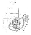
- Fig. 23 shows a state under which the mirror housing 10 is swung forward by the external force P added thereto from back. As seen in Fig. 22, the mirror housing 10 is swung forward in relation to the spindle member 140 by the rotation of the spur gear 135 located on the fixed side, thereby buffering the impact of the external force P.
- Figs. 24 through 29 show a third embodiment of the present invention.
- the third embodiment is fundamentally same in arrangement as the first one. Therefore, only parts which are different from those in the first embodiment will be represented-by different reference numerals, leaving same parts as those in the first embodiment denoted by same reference numerals.
- the base attaching portion 13 which is recessed inward the mirror housing 10 is formed on the base side of the bottom wall of the mirror housing 10.
- the side wall 12 of the mirror housing 10 is arranged to have a curve portion.
- the mount 14 which is projected inward the mirror housing 10 is formed at the base attaching portion 13 of the mirror hous.ing 10.
- a recess 230 and another recess are formed in the mount 14 and the drive transmitting mechanism 30 is housed in the recess 230.
- Another recess 215 has the tapered circumferential wall 15c which is encarged below the base.
- a through-hole 216 is passed through in the recesses 215 and 230 and the cylindrical shaft 41 of the spindle member 40 is passed through the through-hole 216.
- the base 20 has the curved vertical wall 27 which corresponds to the side wall 12 of the mirror housing 10, and it also has the support 21 horizontally extneding from the vertical wall 27 to the side of the mirror housing 10.
- the conical bearing 22 is projected from the support 21.
- the cylindrical shaft 41 of the spindle member 40 is passed through a through-hole 23 which is formed in the center of the bearing 22.
- the spindle member 40 is provided with the cylindrical shaft 41 and the flange 43 formed at the lower end of the cylindrical shaft 41.
- the cylindrical shaft 41 includes a large-diameter portion 243 formed on the side of the flange 43, starting from the cneter thereof, and a small-diameter portion 244 formed on the upper side.
- the hollow portion 49 is formed in the cylindrical shaft 41 and the cord 70 is passed through the hollow portion 49.
- the drive transmitting mechanism 30 comprises a worm wheel 235 fixed to the large-diameter portion 243 attached to the drive motor 31, and a worm 36 located between the two worm wheels 235 and 234.
- the worm 36 includes a large-diameter worm 36a and a small-diameter worm 36b, and the large-diameter worm 36a is engaged with the worm wheel 234 located on the moveble side while the small-diameter worm 36b is engaged with the worm wheel 235 located on the fixed side.
- the buffer mechanism 60 comprises the spring 61 compressed between the engagement groove 46 at the front end of the small-diameter portion 244 of the cylindrical shaft
- the resistant member 262 is made of leather or resin plate, for example.
- Numeral 281 is a packing for water-proof which is fitted into a groove formed on the cover 80.
- the mirror housing, base, drive transmitting mechanism, buffer mechanism and cover are assembled one another as follows in the case of the third embodiment of the present invention.
- the cylindrival shaft 41 of the spindle member 40 is passed through the through-hole 23 in the bearing 22 of the base 20.
- the resistant member 262 is interposed between the cylindrical shaft 41 and the base 20.
- the recess 215 of the mirror housing 10 is fitted onto the bearing 22.
- the cylindrical shaft 41 is passed through the through-hole 216 in the recess 215 into the mirror housing 10 under this state.
- the worm wheel 235, worm 36 and worm wheel 234 of the drive transmitting mechanism 30 are arranged in the recess 230 on the upper face of the mount 14 in such a way that these worm and worm wheels are engaged with one another.
- the worm wheel 235 located on the-fixed side is fixed this time to the large-diameter portion 243 of the yclindrical shaft 41.
- the cover 80 is fixed on the mount 14.
- the cylindrical shaft 41 and motor shaft 33 are passed through the through-holes 84 and 85, respectively, and the drive motor 31 and spring 61 of the buffer mechanism 60 are located on the upper face of the cover this time, similarly to the case of the first embodiment.
- a packing 281 is fitted into a groove 283 on the circumference of the cylindrical shaft 41 at the upper face of the mount 14, water-proof effect can be enhanced.
- the drive motor 31 is rotated to transmit its rotation to the worm wheel 234 located on the movable side.
- the force transmitted is transmitted to the worm wheel 235 on the fixed side through the worm 36.
- the worm wheel 235 is fixed to the spindle member 40 and therefore, it is not rotated. Namely, the mirror housing 10 moves round the cylindrical shaft 41 of the spindle member 40 and on its axis, thereby causing the mirror housing 10 to be swung, sliding on the bearing 22.
- the mirror housing 10 is swung in the reverse direction or forward-when the drive motor 31 is reversely rotated.
- Fig. 29 shows a case where the mirror housing 10 is swung backward by the external force P added thereto from front.
- the worm wheel 234 located on the movable side, worm 36 and worm wheel 235 located on the fixed side become locked, thereby transmitting the rotation force to both of the worm wheel 235 on the fixed side and of the fixed cylindrical shaft 41, and the mirror housing 10 cannot be rotated relative to the base 20 if the load which is applied to the mirror housing 10 is smaller than the certain one.
- the mirror housing 10 is swung backward together with the spindle member 40, exceeding both of the urging force of the spring 61 between the spindle member 40 and the mirror housing 10 and of the frictional force caused by the resistant member 26.
- the worm wheels 234 and 235 are locked through the worm 36, thereby enabling their locked state to be made extremely strong.
- the mirror housing 10 is similarly swung forward when the external force P is added to the mirror housing 10 from back.
- Figs. 30 through 36 show a fourth embodiment of the present invention.
- This fourth embodiment is fundamentally same in arrangement as the first one but it is characterized in that the buffer mechanism is located inside the cover 80 which serves to seal the drive transmitting mechanism 30.
- the base attaching portion 13 which is recessed inward the mirror housing 10 is formed on the base side of the bottom wall 11 of the mirror housing 10.
- the side wall 12 of the mirror housing 10 is provided with a curve portion.
- the mount 14 which is projected inward the mirror housing 10 is formed at the base attaching portion 13 of the mirror housing 10.
- the mount 14 is provided with a recess 315 for a bush 400 which is fitted onto the spindle member 40.
- the through-hole 23 is formed at the bottom of-the recess 315.
- the cylindrical shaft 41 of the spindle member 40 and a cylindrical bearing 401 of the bush 400 the through-hole 23.
- a recess 314 for housing the drive transmitting ; mechanism 30 is formed on the upper face of the mount 14.
- the base 20 includes the curved vertical wall 27 which corresponds to the side wall 12 of the mirror housing 10, and the support 21 extending from the vertical wall 27 toward the mirror housing 10.
- the buffer mechanism attaching portion 24 which has a ring-shaped wall 321 is formed at the support 21.
- the cylindrical shaft 41 of the spindle member 40 is projected from a bottom 324 of the buffer mechanism attaching portion 24.
- the cylindrical shaft 41 is provided with the hollow portion 49 formed therein.
- the bush 400 comproses the cylindrical bearing 401 fitted onto the cylindrical shaft 41 of the spindle member 40, and a flange 402.at the lower end of the cylindrical bearing 401.
- a portion 403 is formed on the outer circumference of the cylindrical bearing 401.
- the worm wheel 335 on the fixed side is attached to the portion 403.
- the underside of the flange 402 is provided with a recess 404.for a ball bearing 68.
- the drive transmitting mechanism 30, similar to the one in the third embodiment, comprises the worm wheel 335 fixed to the bush 400, and the worm wheel 334 attached to the drive motor 31, and these worm wheels are housed in the recess 314 on the upper face of the mount 14 and sealed by the cover 80.
- the cover has through-holes 84 and 85 for the cylindrical shaft 41 and motor shaft 33, and a pressing projection 48 1 on the inner face thereof for pressing the worm wheel 335 on the fixed side.
- the buffer mechanism 60 comprises the spring 61 attached to its attaching portion 24 which is recessed on the support 21, a lide member 461 on the spring 61 provided with recesses 463 for the ball bearings 68 on the upper face thereof and moveble only up and down, and a resistant member 462 arranged between the flange 402 of the bush 400 and the bottom of the recess 315.
- the slide member 461 is limited in rotation because the grooves 465 on its circumferential edge is fitted into a projection 416 on the ring-shaped wall 415 which forms the recess 315.
- the spring 61 is arranged in the attaching portion 24 at the support of the base 20 so as to fit onto the cylindrical shaft 41 of the spindle member 40, and the slide member 461 is located on the spring 61.
- the cylindrical shaft 41 is passed through the through-hole 464 of the slide member 461, while the projection 465 on the circumferential edge of the slide member 461 are fitted to projection 416, thereby limitting the rotation of the slide member 461.
- the ball bearing 68 are arranged in the recesses 463 on the upper face of the slide member 461.
- the resistance member 462 is arranged on the flange 402 of the bush 400 which is located onto the ball bearings 68, and the cylindrical shaft 41 is passed through the cylindrical bearing 401 of the bush 400.
- the recess 315 of the mirror housing 10 is fitted onto the bush 400, allowing the bush 400 and cylindrical shaft 41 to be passed through the through-hole 23 in the bottom of the recess 315.
- the worm wheel 335 on the fixed side is fixed to a portion of the cylindrical bearing 401 which is projected from the recess 314 on the mount 14 of the mirror housing 10.
- the worm wheel 334 fixed to the motor shaft 33 is engaged with the worm 36, and they are sealed by the cover 80, similarly to the cases of the above-described embodiments.
- the cover 80 presses the worm wheel 335 by its projections 481 and is fixed to the cylindrical shaft 41 by means of the clip 65.
- Figs. 34 and 35 it will be described how the mirror housing 10 is swung by remote operation.
- the drive motor 31 is rotated and its rotation is reduced by the speed reducer 32 and transmitted to the worm wheel 334.
- the rotation force is transmitted to the worm wheel 335 through the worm 36 to rotate the worm wheel 334.
- the worm wheel 335 is fixed to the bush 400, whose rotation is prevented by the compressing force of the spring 61 which is added to the resistant member 462 and ball bearing 68. therefore, the worm 36 and worm wheel 334 moves round the worm wheel 335 and on their axis, respectively, thereby causing-the mirror housing 10 to swing round the cylindrical shaft 41.
- Fig. 36 shows a case where the drive motor 31 is reversely rotated to swing the mirror housing 10 forward.
- Fig. 37 shows a state under which the mirror housing 10 is swung backward by the external force P added thereto from front.
- Fig. 38 shows a state under which the mirror housing 10 is swung reverse to the case shown in Fig. 37 by reversely rotating the drive motor 31.
- the drive transmitting mechanism 30 and buffer mechanism 60 are sealed to thereby enhance the water-proof effect.
Landscapes
- Engineering & Computer Science (AREA)
- Multimedia (AREA)
- Mechanical Engineering (AREA)
- Rear-View Mirror Devices That Are Mounted On The Exterior Of The Vehicle (AREA)
Abstract
Description
- The present invention relates to an outside rear view mirror for cars provided with a drive transmitting mecha- nism for electrically swinging its-mirror housing relative to the base.
- The outside rear view mirrors have been widely used for cars and one of them is disclosed by U.S. Patent No. 4,213,675. Figs. 1 and 2 of this patent show the conventional outside rear view mirror, in which Fig. 1 is a vertically-sectioned view" thereof and Fig. 2 a partially-sectioned view thereof.
- As shown in Figs. 1 and 2, the mirror housing (3) is swingably attached to the body (6) by means of a plate-like arm (17) and a screw (15) in the case of this conventional outside rear view mirror (4).
- The plate-like arm (17) is engaged with the boss of the mirror housing (3) by means of plural projections. The mirror housing (3), plate-like arm (17) and body (7) are held, pressed against one another, by a spring (38).
- In the case of this conventional outside rear view mirror (4), the mirror housing (3) is displaced forward or backward, taking the screw (15) as its center, when the handle (21) is moved forward or backward in Fig. 1. When the handle (21) is rotated, taking the center axis of the plate-like arm (17) as its center, the mirror housing (3) is displaced up and down.
- When excessive load is added to the mirror housing (3), the mirror housing (3) is released from the plate-like arm (17) and swung toward the door (2).
- The above-described conventional outside rear view mirror (4) is most suitable for use as a device whose range of vision can be adjusted by the handle (21).
- As apparent from Figs. 1 and 2, however, forward or backward displacement of the mirror housing (3) is determined by the amount of handle (21) operation carried out in the car room. This amount of handle (21) operation is limitted to a range necessary to adjust the field of vision allowed by the mirror (4). When it is wanted that the mirror housing (3) which is projected outside the car body is swung over the range of adjusting the field of vision and displaced to contact with the car body at the time of transporting or garaging the car, the mirror housing must be forcedly swung against the spring (28) and released from the boss projections (16). Namely, the mirror housing must be brought under such state-that, impact has been artificially added to the mirror housing (3).
- It was therefore needed.that the swing operation was carried out outside the car-body. In addition, the swing operation was considerably difficult because it must be carried out against the spring which was pressed against the mirror housing (3) and body (7).
- The object of the present invention is to provide and outside rear view mirror which can be remotely operated in the car room to swing the mirror housing relative to the base and displace it toward the car body.
- The object of the present invention can be achieved by an outside rear view mirror comprising a base to which a mirror housing, which adjustably holds a mirror, is swingably attached through a spindle member, a drive transmitting mechanism for remotely operating the mirror housing to automatically swing it in relation to the base, and a buffer mechanism arranged between the mirror housing and the base.
-
- Figs. 1 and 2 shows one of the conventional outside rear view mirrors;
- Fig. 1 is a vertically-sectioned view showing the mirror attached to the door of a car.
- Fig. 2 is a horizontally-sectioned view showing an adjustment means used for the mirror in Fig. 1.
- Figs. 3 through 17 show an embodiment of the present invention.
- Fig. 3 shows an outside rear view mirror attached to the car.
- Fig. 4 is a front view showing the outside rear view mirror partially sectioned.
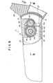
- Fig. 5 is a view partially sectioned alobg the line A-A in Fig. 4.
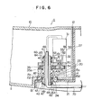
- Fig. 6 is a view taken along the line B-B in Fig. 5.
- Fig. 7 is an exploded view showing main parts of the mirror.
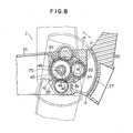
- Fig. 8 is a view similar to Fig. 5 and showing a mirror housing automaticlly swung.
- Fig. 9 is a view similar to Fig. 5 and showing the mirror housing forcedly swung backward as the result of its being impacted from front.
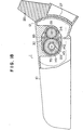
- Fig. 10 is a view similar to Fig. 5 and showing the mirror housing forcedly swung forward as the result of its being impacted from back.
- Fig. 11 is a front view showing a spindle member.
- Fig. 12 is a view showing a part of the spindle member sectioned horizontally.
- Fig. 13 shows the spindle member viewed in the direction of an arrow A in Fig. 11.
- Fig. 14 shows the spindle memeber viewed in the direction of an arrow B in Fig. 10.
- Fig. 15 is a plan showing the main portion of a base.
- fig. 16 is a sectional view taken along a line C-C in Fig. 15.
- Fig. 17 is a sectional view taken along a line D-D in Fig. 15.
- Figs. 18 through 23 show a second embodiment of the present invention.
- Fig. 18 is a plan similar to Fig. 5.
- Fig. 19 is an enlarged sectional view similar to Fig. 6.
- Fig. 20 is an exploded view showing main parts of mirror.
- Fig. 21 is a view similar to Fig. 8.
- Fig. 22 is a view similar to Fig. 9.
- Fig. 23 is a view similar to Fig. 10.
- Figs. 24 through 29 show a third embodiment of the present invention.
- Fig. 24 is a front view showing an outside rear view mirror partially sectioned.
- Fig. 25 is a sectional view taken along the line E-E in Fig. 25.
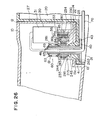
- Fig. 26 is an enlarged sectional view taken along the line F-F in Fig. 25.
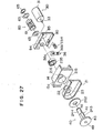
- Fig. 27 is an exploded view showing the main parts of the mirror.
- Fig. 28 is a view similar to Fig. 8.
- Fig. 29 is a view similar to Fig. 9.
- Figs. 30 through 38 show a fourth embodiment of the present invention.
- Fig. 30 is a front view showing an outside rear view mirror partially sectioned.
- Fig. 31 is a sectional view taken along the line G-G in Fig. 30.
- fig. 32 is an enlarged sectional view taken along the line H-H in Fig. 31.
- Fig. 33 is a plan showing a bush.
- Fig. 34 is an exploded view showing the main parts of the mirror.
- Fig. 35 is a view similar to Fig. 31 and showing the mirror housing automatically swung backward.
- Fig. 36 is a view similar to Fig. 31, showing the mirror housing automatically swung forward.
- Fi-g. 37 is a view similar-to Fig. 9.
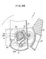
- Fig. 38 is a view similar to Fig. 10.
- Figs. 3 through 17 show a first embodiment of the present invention.
- As shown in detail in Figs. 3 through 17, an outside
rear view mirror 1 comprises amirror housing 10 for adjustably holding amirror 50 in the opening thereof, a base 20 to which themirror housing 10 is swingably attached through aspindle member 40, adrive transmitting mechanism 30 for swinging themirror housing 10 relative to thebase 20, and abuffer mechanism 60 located between themirror housing 10 and the spindle member. As shown in Fig. 3, the outsiderear view mirror 1 is attached to acar body 90 in such a way that is is projected only by distance ℓ thecar body 90. - As shown Tin Figs. 4 and 5, the
mirror housing 10 is of the rectangular type, having longer horizontal sides, and formed different from thebase 20. Themirror 50 is held in the opening of themirror housing 10 to adjust the field of vision. - The
mirror housing 10 is swingably supported by the base 20 through the spindle member, and abuffer mechanism 60 which comprisessprings mirror housing 10 and thebase 20 and between the base 20 and thespindle member 40, respectively, serves to buffer such impact that is larger than a certain load. This impact buffering can be attained in such a way that themirror housing 10 andspindle member 40 are swung round thebase 20 against thesprings mirror housing 10 of the outside rear view mirror which comprises themirror housing 10,.base 20 andspindle member 40 urged by thesprings mirror housing 10 is swung round thespindle member 40 by remotely operating thedrive transmitting mechanism 30 in the car room except the case where it is forcedly swung by the strong impact as described above. - As shown in Figs. 6 and 7, to describe the arrangement of the
mirror housing 10 in more detail, abase attaching portion 13 which is recessed inward a bottom wall 11 of themirror housing 10 is formed at that portion of the bottom wall 11 of themirror housing 10 which is located on the side of thebase 20. Aside wall 12 of themirror housing 10 is arranged to have a curve portion. Amount 14 is projected from thebase attaching portion 13 inward themirror housing 10. Thespindel member 40 passing through a through-hole 15 which is to formed in themount 14. Themount 14 includes a taperedcircumference 15c, having an upper small-diameter portion 15a and a lower large-diameter portion 15b, and a ring-shapedrecess 15d around the large-diameter portion 15b. - The
base 20 has avertical wall 27 provided with a curve portion which corresponds to theside wall 12 of themirror housing 10, and asupport 21 which extends hofizontally from thevertical wall 27 toward themirror housing 10. - As shown in Figs.15 to 17, a
conical bearing 22 is projected from thesupport 21. Aspring attaching portion 24 is formed on the underside of thebearing 22 and a-through-hole 23 through which acylindrical shaft 41 of thespindle member 40 passes is formed in thebearing 22, extending from the bottom of thespring attaching portion 24 to the upper side of thebearing 22. Threeprojections 26 are formed on the circumference of the bearing 22 of thebase 20, each separated from the others at an angle of 120°. - As shown.in Figs. 11 through 14, the
spindle member 40 includes acylindrical shaft 41 and a conical ring-shapedwall 42 which is enlarged downward and which is integrally formed at the center portion of thecylindrical shaft 41. A ring-shapedrecess 44 whose outer wall is tapered or enlarged downward is formed between thecylindrical shaft 41 and the conical ring-shapedwall 42. Engagement recesses 48 are formed, each separated from the others at an angle of 120°, on the lower and face of the ring-shapedwall 42. These engagement recesses 48 are engaged with theprojections 26 on thebase 20. A spurgear attaching portion 45 is formed on thecylindrical shaft 41 and aspur gear 35 located on the fixed side of thetransmitting mechanism 30 is attached is formed on thecylindrical shaft 41. The spurgear attaching portion 45 has a D-shaped section and located adjacent of the top of the ring-shapedwall 42. Formed on the upper and lower ends of thecylindrical shaft 41 arerecesses springs buffer mechanism 60. - A
cord 70 which is connected to adrive motor 31 for thedrive transmitting mechanism 30 is inserted through ahollow portion 49 of thecylindrical shaft 41.. - The
drive transmitting mechanism 30 comprises thespur gear 35 which is located on the fixed side and which is fixed to theportion 45 of thecylindrical shaft 41, anotherspur gear 34 which is engaged with thespur gear 35, fixed to amotor shaft 33 of thedrive motor 31, and located on the movable side, the drive motor for rotating thespur gear 34, and aspeed reducer 32. - The
buffer mechanism 60 comprises thespring 61 which is compressed between theengagement recess 46 located on the upper end side of thecylindrical shaft 41 and the upper face of acover 80 by means of twowashers 63 and aclip 65, and thespring 62 which is compressed in thespring attaching portion 24 of the base 20 by means of theclip 66 and twowashers 64, saidclip 66 being fitted into theengagement recess 47 located on the lower end side of thecylindrical shaft 41. Thecover 80 serves to seal the twospur gears drive transmitting mechanism 30, and includes a through-hole 84 for thecylindrical shaft 41, a through-hole 85 for themotor shaft 31, and abearing 82 for thespur gear 34. - The mirror housing, base, spindle member drive transmitting mechanism and cover are assembled one another as follows.
- The
spindle member 40 is attached to thebearing 22 projected from thesupport 21 of thebase 20. Thecylindrical shaft 41 of thespindle member 40 is passed through the through-hole 23-in the bearing 22 of thebase 20 and thespring attaching protion 24 and projected below thebase 20 under this state. Tapered ring-shapedrecess 44 between thecylindrical shaft 41 of thespindle member 40 and the ring-shapedwall 42 is fitted onto thebearing 22 and their tapered faces are contacted each other. The engagement recesses 48 on the bottom face of theflange 43 of the ring-shapedwall 42 are fitted onto theprojections 26 on the circumference of thebearing 22 at thesupport 21 of the base 20 to thereby set thespindle member 40 at a desired position. - - The
mirror housing 10 is then attached to thespindle member 40 which has been set to thebase 20. The through-hole 15 in themount 14 of themirror housing 10 is fitted onto the ring-shapedwall 42 of thespindle member 40 under this state. At this time, both of the ring-shapedwall 42 and through-hole 15 are contacted with each other and the upper end portion of thecylindrical shaft 41 is projected inward themirror housing 10. - .fitted onto the spur
gear attaching portion 45 of thecylindrical shaft 41 which is projected from themount 14 of themirror housing 10 is thespur gear 35 located on the fixed side. At this time, ashaft 35a of thespur gear 35 is fitted into the through-hole 15 and both of thespur gear 35 and spurgear attaching portion 45 of thecylindrical shaft 41 are fitted each other not to rotate relative to the other. Thespur gear 34 located on the movable side is set on themount 14 to engage thespur gear 35 and these are sealed by the;cover 80. Thecylindrical shaft 41 is projected through the through-hole 84 in the cover inward themirror housing 10, and themotor shaft 33 of thedrive motor 31 on the top of thecover 80 is passed through the through-hole 85, with thespeed reducer 32 interposed, into thehollow portion 81 in thecover 80 to fit into thespur gear 34. Ashaft 34a of thisspur gear 34 is supported by the bearing 82 of thecover 80. Thecover 80 is fixed on.themount 14 by means of a screw 83 (See fig. 5). - The
drive motor 31 andspeed reducer 32 are attached to the top of thecover 80, and thecord 70 is introduced outside through thehollow portion 49 in thecylindrical shaft 41. - The
buffer mechanism 60 is attached to the assembly thus obtained. More specifically, thespring 61 which is - interposed between the twowashers 63 is fitted onto thecylin drical shaft 41 projected from the top of thecover 80 and compressed and fixed by theclip 65 fitted onto theengagement recess 46. Thespring 62 which is interposed between the twowashers 64 is similarly attached to the lower end of thecylindrical shaft 41 projected at thespring attaching portion 24 of thebase 20 and it is compressed and fixed by theclip 66 fitted onto theengagement recess 47. Therefore, the tapered faces 25, 44a, 42a and 15c of the bearing 22 of thebase 20, of the ring-shapedwall 42 of thespindle member 40, of the ring-shapedwall 42, and of the through-hole 15 in themount 14 of themirror housing 10 are forcedly contacted with one acnother by thesprings projections 26 to be forcedly engaged with the engagement recesses 48. - It will be described how the
mirror housing 10 is swung by remote operation, referring to Fig. 8. - In a case where the
mirror housing 10 is swung backward, for example, thedrive motor 31 is rotated and its rotation is transmitted to thespur gear 34 through thespeed reducer 32. Since thespur gear 34 is engaged with thespur gear 35 located on the fixed side, the rotation is transmitted in a direction in which thespur gear 35 is rotated. However, thespur gear 35 located on the fixed side is unswingably attached to thecylindrical shaft 41 of thespindle member 40 and thisspindle member 40 is limited in its swinging movement by the twosprings buffer mechanism 60 and by the engagement between theprojections 26 and the engagement recesses 48 in such a way that it is not swung by any load- smaller than the certain load. Therefore, thespur gear 35 is fixed and the anotherspur gear 34 moves around thespur gear 35 and on its axis. Themirror housing 10 which fixes thespur gear 34 thus moves round thecylindrical shaft 41 and slides on the taperedface 44a of thespindle member 40 to swing backward. - In a case where the
mirror housing 10 is swung forward, thedrive motor 31 is reversly rotated to reversely rotate thespur gear 34. - Referring to Figs. 9 and 10, it will be described how the impact exerted by external force P is buffered when the
mirror housing 10 is forcedly swung by the external force P added thereto. - Fig. 9 shows a case where the
mirror housing 10 is swung backward by the external force P added thereto from front. - When the external force P is added to the
mirror housing 10, the two spur.gears 34 and 35 become locked and both of themirror housing 10 andspindle member 40 become unswingable. Therefore, rotating force caused by the external force P serves to make themirror housing 10 andspindle member 40 cooperative to each other. When this rotating force exceeds the engagement force between the engagement recesses 48 of thespindle member 40 and theprojections 26 on thebase 20 and the compressing force of the twosprings mirror housing 10 is slid and swung together with thespindle member 40 on the taperedface 25 of the bearing 22 in relation to thebase 20, thereby enabling the impact of the external force P to be buffered by their swinging movement. - Fig. 10 shows a case where the
mirror housing 10 is swung forward by the external force P added thereto from back. As described above referring to Fig. 9,themirror housing 10 andspindle member 40 are simultaneously slid and swung forward on the tapered face of the bearing 22 of thebase 20, thereby buffering the impact of the external force P. - When arranged as described above, the mirror housing can be easily swung by remote operation in the car room to become parallel to the outside of the car body at the time of transporting the car to which the outside rear view mirrors . are attached or garaging it, thereby enabling car transportation space to be made smaller and preventing the mirror housings from becoming obstacles at the time of garaging the car.
- Further, the buffer mechanism is arranged between the mirror housing and the base. Therefore, the mirror housing is swung to buffer impact even when the impact is added to the mirror housing, thereby proventing reducing the damage of human beings and the outside
rear view mirror 1. - Furthermore, the
mirror housing 10,base 20 andspindle member 40 are slidably contacted with one another at their conical tapered faces. Therefore, the outsiderear view mirror 1 is excellent in stability and it hardly happens that the field of vision is made worse by the vibration of themirror 50. - Figs. 18 through 23 show a second embodiment of the present invention, which is fundamentally similar to the first embodiment.
- Since the mirror housing, base, cover and buffer mechanism are almost same as those in the first embodiment, they are represented by same reference numerals, but parts which are different from those in the first embodiment will be denoted by different reference numerals and described below.
- As shown in Fig. 20, the through-
hole 23 in the bearing 22 of thebase 20 is provided with a pair ofkey grooves 123. - The
spindle member 140 has acylindrical shaft 141. Twoprojection 142 and a conical slide-contact wall 144 spaced therefrom are farmed integrally to the cylindrical shaft 141.-A portion between theprojections 142 and the conical slide-contact wall 144 is a spur gear attaching portion for attaching aspur gear 135. The conical slide-contact wall 144 is enlarged upward and thespur gear 135 being located on the fixed side. - The
drive transmitting mechanism 30 is substantially same in arrangement as in the first embodiment, but a taperedrecess 36 is formed on the upper poetion of the through-hole 37, of thespur gear 135 located on the fixed side. Further, a pair ofgrooves 137 are formed on the inner wall of the through-hole 37. Theprojections 142 on thecylindrical shaft 141 are passed through thegrooves 137, respectively. - As shown in Figs. 18 and 19, these base, mirror housing, spindle member and drive transmitting mechanism are assembled one another as follows.
- The through-
hole 15 of themirror housing 10 is fitted onto the bearing 22 of the base 20 to locate themirror housing 10 on thebase 20, thespur gear 135 is positioned on bearing 22, and thecylindrical shaft 141 of thespindle member 40 is then inserted into the assembly from above. Theprojections 142 on thecylindrical shaft 141 are passed through the pairedgrooves 137 which are formed on the inner face of through-hole 37 of thespur gear 135 located on the fixed side, and they are fitted, movable up and down, into the key grooves in the bearing 22 of thebase 20. Thespur gear 34 located on the movable side is then engaged with thespur gear 135 located on the fixed side and thecover 80 seals these spur gears of thedrive transmitting mechanism 30. Themirror housing 10 is pressed against thebase 20, using thesprings lips washers buffer mechanism 60. - Referring to Fig. 21, it will be described how the
mirror housing 10 is swung by remote operation. - In a case where the
mirror housing 10 is swung backward, for example, thedrive motor 31 is rotated, and its rotation is reduced by thespeed reducer 32 and transmitted to thespur gear 34.. Since thespur gear 34 is engaged with thespur gear 135 located on the fixed side, the rotation is transmitted to thespur gear 135 to rotate it, but thespur gear 135 located on the fixed side is slide-contacted with the tapered face between therecess 36 and the slide-contact wall 144 on thecylindrical shaft 141 and compressive force is applied to the tapered slide-contact face by means of thesprings spur gear 135 not rotated. Therefore, thespur gear 34 moves round thespur gear 135 and on its axis, and themirror housing 10 is thus swung backward. - In a case where the
mirror housing 10 is swung forward, thedrive motor 31 is reversely rotated to reversely rotate thespur gear 34. - Fig. 22 shows a state under which the
mirror housing 10 is swung backward by external force P added thereto from front. - When the external force P is added to the
mirror housing 10, as shown in Fig. 22, the spur gears 34 and 135 become locked and the mirror housing'10 becomes unrotatable together with thespindle member 140 if the load which is added to themirror housing 10 is smaller than the certain load. When the impact of the external force P is strong, however, thespur gear 135 is rotated relative to thespindle member 140, exceeding frictional force between thespindle member 140 and thespur gear 135 located on the fixed side. This.is because the frictional force between the slide-contact wall 144 on thespindle member 140 and therecess 36 on thespur gear 135 is caused by thesprings spindle member 140 cannot rotate but move only up and down since it is engaged with thekey grooves 123, and because thespindle member 140 is moved upward and released from its frictional engagement with thespur gear 135 when the external force P is stronger than the urging force of thesprings - Fig. 23 shows a state under which the
mirror housing 10 is swung forward by the external force P added thereto from back. As seen in Fig. 22, themirror housing 10 is swung forward in relation to thespindle member 140 by the rotation of thespur gear 135 located on the fixed side, thereby buffering the impact of the external force P. - - When the
mirror housing 10 is swung to its final positon in relation to the base and the rotation force of the drive motor is still added to thespur gear 135 located on the fixed side in the case of this second embodiment, the frictional engagement between the slide-contact wall 144 ofspindle member 140 and thespur gear 135 located on the fixed side is released, as shown in Figs. 22 and 23, thereby preventing excessive load from being added to thedrive motor 31. - In the case of this second embodiment arranged as described above, excessive load can be prevented from being added to the drive motor, in addition to same effects as those attained by the first embodiment.
- Figs. 24 through 29 show a third embodiment of the present invention.
- The third embodiment is fundamentally same in arrangement as the first one. Therefore, only parts which are different from those in the first embodiment will be represented-by different reference numerals, leaving same parts as those in the first embodiment denoted by same reference numerals.
- As shown in Figs. 24 to 26, the
base attaching portion 13 which is recessed inward themirror housing 10 is formed on the base side of the bottom wall of themirror housing 10. Theside wall 12 of themirror housing 10 is arranged to have a curve portion. Themount 14 which is projected inward themirror housing 10 is formed at thebase attaching portion 13 of themirror hous.ing 10. Arecess 230 and another recess are formed in themount 14 and thedrive transmitting mechanism 30 is housed in therecess 230. Anotherrecess 215 has the taperedcircumferential wall 15c which is encarged below the base. A through-hole 216 is passed through in therecesses cylindrical shaft 41 of thespindle member 40 is passed through the through-hole 216. - The
base 20 has the curvedvertical wall 27 which corresponds to theside wall 12 of themirror housing 10, and it also has thesupport 21 horizontally extneding from thevertical wall 27 to the side of themirror housing 10. Theconical bearing 22 is projected from thesupport 21. Thecylindrical shaft 41 of thespindle member 40 is passed through a through-hole 23 which is formed in the center of thebearing 22. - As shown in Fig. 27, the
spindle member 40 is provided with thecylindrical shaft 41 and theflange 43 formed at the lower end of thecylindrical shaft 41. Thecylindrical shaft 41 includes a large-diameter portion 243 formed on the side of theflange 43, starting from the cneter thereof, and a small-diameter portion 244 formed on the upper side. Thehollow portion 49 is formed in thecylindrical shaft 41 and thecord 70 is passed through thehollow portion 49. - As shown in Figs. 25 and 26, the
drive transmitting mechanism 30 comprises aworm wheel 235 fixed to the large-diameter portion 243 attached to thedrive motor 31, and aworm 36 located between the twoworm wheels worm 36 includes a large-diameter worm 36a and a small-diameter worm 36b, and the large-diameter worm 36a is engaged with theworm wheel 234 located on the moveble side while the small-diameter worm 36b is engaged with theworm wheel 235 located on the fixed side. - The
buffer mechanism 60 comprises thespring 61 compressed between theengagement groove 46 at the front end of the small-diameter portion 244 of the cylindrical shaft - 41 and the upper face of the
cover 80 by means of the twowashers 63 andclip 65, and aresistant member 262 located between theflange 43 at the lower end of the large-diameter portion 243 of thecylindrical shaft 41 and thebase 20. Theresistant member 262 is made of leather or resin plate, for example. -
Numeral 281 is a packing for water-proof which is fitted into a groove formed on thecover 80. - The mirror housing, base, drive transmitting mechanism, buffer mechanism and cover are assembled one another as follows in the case of the third embodiment of the present invention.
- As ahown in Fig. 26, the
cylindrival shaft 41 of thespindle member 40 is passed through the through-hole 23 in the bearing 22 of thebase 20. At this time, theresistant member 262 is interposed between thecylindrical shaft 41 and thebase 20. Therecess 215 of themirror housing 10 is fitted onto thebearing 22. Thecylindrical shaft 41 is passed through the through-hole 216 in therecess 215 into themirror housing 10 under this state. Theworm wheel 235,worm 36 andworm wheel 234 of thedrive transmitting mechanism 30 are arranged in therecess 230 on the upper face of themount 14 in such a way that these worm and worm wheels are engaged with one another. Theworm wheel 235 located on the-fixed side is fixed this time to the large-diameter portion 243 of theyclindrical shaft 41. Thecover 80 is fixed on themount 14. Thecylindrical shaft 41 andmotor shaft 33 are passed through the through-holes drive motor 31 andspring 61 of thebuffer mechanism 60 are located on the upper face of the cover this time, similarly to the case of the first embodiment. When a packing 281 is fitted into agroove 283 on the circumference of thecylindrical shaft 41 at the upper face of themount 14, water-proof effect can be enhanced. - A case where the
mirror housing 10 is swung backward by remote operation will be described, referring to Fig. 28. - The
drive motor 31 is rotated to transmit its rotation to theworm wheel 234 located on the movable side. The force transmitted is transmitted to theworm wheel 235 on the fixed side through theworm 36. However, theworm wheel 235 is fixed to thespindle member 40 and therefore, it is not rotated. Namely, themirror housing 10 moves round thecylindrical shaft 41 of thespindle member 40 and on its axis, thereby causing themirror housing 10 to be swung, sliding on thebearing 22. - Although not shown, it can be easily understood that the
mirror housing 10 is swung in the reverse direction or forward-when thedrive motor 31 is reversely rotated. - Fig. 29 shows a case where the
mirror housing 10 is swung backward by the external force P added thereto from front. - When the external force P is added to the
mirror housing 10 as shown in Fig. 29, theworm wheel 234 located on the movable side,worm 36 andworm wheel 235 located on the fixed side become locked, thereby transmitting the rotation force to both of theworm wheel 235 on the fixed side and of the fixedcylindrical shaft 41, and themirror housing 10 cannot be rotated relative to the base 20 if the load which is applied to themirror housing 10 is smaller than the certain one. When the external force P is strong, however, themirror housing 10 is swung backward together with thespindle member 40, exceeding both of the urging force of thespring 61 between thespindle member 40 and themirror housing 10 and of the frictional force caused by theresistant member 26. In the case of the third embodiment as described above, theworm wheels worm 36, thereby enabling their locked state to be made extremely strong. - Although not shown, the
mirror housing 10 is similarly swung forward when the external force P is added to themirror housing 10 from back. - Figs. 30 through 36 show a fourth embodiment of the present invention. This fourth embodiment is fundamentally same in arrangement as the first one but it is characterized in that the buffer mechanism is located inside the
cover 80 which serves to seal thedrive transmitting mechanism 30. - Therefor, parts which are different from those in the first embodiment will be denoted by different reference numerals and described below, leaving same parts as those in --the first embodiment represented by same reference numerals.
- As shown in Figs. 30 to 34, the
base attaching portion 13 which is recessed inward themirror housing 10 is formed on the base side of the bottom wall 11 of themirror housing 10. Theside wall 12 of themirror housing 10 is provided with a curve portion. Themount 14 which is projected inward themirror housing 10 is formed at thebase attaching portion 13 of themirror housing 10. Themount 14 is provided with arecess 315 for abush 400 which is fitted onto thespindle member 40. The through-hole 23 is formed at the bottom of-therecess 315. Thecylindrical shaft 41 of thespindle member 40 and acylindrical bearing 401 of thebush 400 the through-hole 23. - A
recess 314 for housing the drive transmitting ;mechanism 30 is formed on the upper face of themount 14. - The
base 20 includes the curvedvertical wall 27 which corresponds to theside wall 12 of themirror housing 10, and thesupport 21 extending from thevertical wall 27 toward themirror housing 10. The buffermechanism attaching portion 24 which has a ring-shapedwall 321 is formed at thesupport 21. Thecylindrical shaft 41 of thespindle member 40 is projected from a bottom 324 of the buffermechanism attaching portion 24. Thecylindrical shaft 41 is provided with thehollow portion 49 formed therein. - The
bush 400 comproses thecylindrical bearing 401 fitted onto thecylindrical shaft 41 of thespindle member 40, and a flange 402.at the lower end of thecylindrical bearing 401. Aportion 403 is formed on the outer circumference of thecylindrical bearing 401. Theworm wheel 335 on the fixed side is attached to theportion 403. The underside of theflange 402 is provided with a recess 404.for aball bearing 68. - The
drive transmitting mechanism 30, similar to the one in the third embodiment, comprises theworm wheel 335 fixed to thebush 400, and theworm wheel 334 attached to thedrive motor 31, and these worm wheels are housed in therecess 314 on the upper face of themount 14 and sealed by thecover 80. - The cover has through-
holes cylindrical shaft 41 andmotor shaft 33, and apressing projection 481 on the inner face thereof for pressing theworm wheel 335 on the fixed side. - The
buffer mechanism 60 comprises thespring 61 attached to its attachingportion 24 which is recessed on thesupport 21, alide member 461 on thespring 61 provided withrecesses 463 for theball bearings 68 on the upper face thereof and moveble only up and down, and aresistant member 462 arranged between theflange 402 of thebush 400 and the bottom of therecess 315. Theslide member 461 is limited in rotation because thegrooves 465 on its circumferential edge is fitted into aprojection 416 on the ring-shaped wall 415 which forms therecess 315. - These
mirror housing 10,base 20, drive transmittingmechanism 30,spindle member 40,bush 400 andbuffer mechanism 60 are assembled one another as follows. - As shown in Fig. 32, the
spring 61 is arranged in the attachingportion 24 at the support of the base 20 so as to fit onto thecylindrical shaft 41 of thespindle member 40, and theslide member 461 is located on thespring 61. At this time, thecylindrical shaft 41 is passed through the through-hole 464 of theslide member 461, while theprojection 465 on the circumferential edge of theslide member 461 are fitted toprojection 416, thereby limitting the rotation of theslide member 461. Theball bearing 68 are arranged in therecesses 463 on the upper face of theslide member 461. - The
resistance member 462 is arranged on theflange 402 of thebush 400 which is located onto theball bearings 68, and thecylindrical shaft 41 is passed through thecylindrical bearing 401 of thebush 400. - The
recess 315 of themirror housing 10 is fitted onto thebush 400, allowing thebush 400 andcylindrical shaft 41 to be passed through the through-hole 23 in the bottom of therecess 315. - The
worm wheel 335 on the fixed side is fixed to a portion of thecylindrical bearing 401 which is projected from therecess 314 on themount 14 of themirror housing 10. Theworm wheel 334 fixed to themotor shaft 33 is engaged with theworm 36, and they are sealed by thecover 80, similarly to the cases of the above-described embodiments. Thecover 80 presses theworm wheel 335 by itsprojections 481 and is fixed to thecylindrical shaft 41 by means of theclip 65. - Referring to Figs. 34 and 35, it will be described how the
mirror housing 10 is swung by remote operation. - In a case where the
mirror housing 10 is swung backward as shown in Fig. 35, for example, thedrive motor 31 is rotated and its rotation is reduced by thespeed reducer 32 and transmitted to theworm wheel 334. The rotation force is transmitted to theworm wheel 335 through theworm 36 to rotate theworm wheel 334. However, theworm wheel 335 is fixed to thebush 400, whose rotation is prevented by the compressing force of thespring 61 which is added to theresistant member 462 andball bearing 68. therefore, theworm 36 andworm wheel 334 moves round theworm wheel 335 and on their axis, respectively, thereby causing-themirror housing 10 to swing round thecylindrical shaft 41. - Fig. 36 shows a case where the
drive motor 31 is reversely rotated to swing themirror housing 10 forward. - Fig. 37 shows a state under which the
mirror housing 10 is swung backward by the external force P added thereto from front. - When the external force P is added to the
mirror housing 10 in these cases, theworm wheel 335,worm 36 andworm wheel 334 become locked and both of themirror housing 10 andbush 400 become unswingable in relation to thecylindrical shaft 41 of thespindle member 40 projected into therecess 24 of thebase 20, if the load which is added to themirror housing 10 is smaller than the certain load. When the impact of the external force P is strong, however, themirror housing 10 andbush 400 are swung against the compressing force of thespring 61 by separating the ball bearings from either recesses, thereby causing themirror housing 10 to be swung backward. - Fig. 38 shows a state under which the
mirror housing 10 is swung reverse to the case shown in Fig. 37 by reversely rotating thedrive motor 31. - In the case of the fourth embodiment of the present invention, the
drive transmitting mechanism 30 andbuffer mechanism 60 are sealed to thereby enhance the water-proof effect.
Claims (20)
Applications Claiming Priority (8)
| Application Number | Priority Date | Filing Date | Title |
|---|---|---|---|
| JP58237187A JPS60131341A (en) | 1983-12-17 | 1983-12-17 | Door mirror |
| JP237188/83 | 1983-12-17 | ||
| JP58237188A JPS60131342A (en) | 1983-12-17 | 1983-12-17 | door mirror |
| JP237187/83 | 1983-12-17 | ||
| JP53491/84 | 1984-04-13 | ||
| JP5349184U JPS60173432U (en) | 1984-04-13 | 1984-04-13 | Foldable door mirror |
| JP8921584U JPS613752U (en) | 1984-06-15 | 1984-06-15 | Electrically foldable door mirror |
| JP89215/84 | 1984-06-15 |
Related Child Applications (1)
| Application Number | Title | Priority Date | Filing Date |
|---|---|---|---|
| EP87111698.4 Division-Into | 1987-08-12 |
Publications (3)
| Publication Number | Publication Date |
|---|---|
| EP0146888A2 true EP0146888A2 (en) | 1985-07-03 |
| EP0146888A3 EP0146888A3 (en) | 1985-08-07 |
| EP0146888B1 EP0146888B1 (en) | 1989-03-22 |
Family
ID=27462903
Family Applications (2)
| Application Number | Title | Priority Date | Filing Date |
|---|---|---|---|
| EP84115371A Expired EP0146888B1 (en) | 1983-12-17 | 1984-12-13 | Outside rear view mirror |
| EP87111698A Expired EP0255150B1 (en) | 1983-12-17 | 1984-12-13 | Outside rear view mirror |
Family Applications After (1)
| Application Number | Title | Priority Date | Filing Date |
|---|---|---|---|
| EP87111698A Expired EP0255150B1 (en) | 1983-12-17 | 1984-12-13 | Outside rear view mirror |
Country Status (3)
| Country | Link |
|---|---|
| US (1) | US4681409A (en) |
| EP (2) | EP0146888B1 (en) |
| DE (3) | DE3485663D1 (en) |
Cited By (8)
| Publication number | Priority date | Publication date | Assignee | Title |
|---|---|---|---|---|
| EP0166378A1 (en) * | 1984-06-28 | 1986-01-02 | Murakami Kaimeido Co., Ltd | Electrically foldable door mirror |
| EP0169245A4 (en) * | 1984-01-12 | 1986-06-11 | Ichikoh Industries Ltd | REMOTE CONTROLLED SIDE MIRROR FOR MOTOR VEHICLE. |
| EP0182260A3 (en) * | 1984-11-12 | 1987-03-18 | Ichikoh Industries Limited | Motor-driven collapsible door motor |
| EP0367134A1 (en) * | 1988-11-02 | 1990-05-09 | Dante Siano | Device to control the rotation of an external rear-view mirror |
| FR2662124A1 (en) * | 1990-05-15 | 1991-11-22 | Gilardini Spa | VEHICLE MIRROR. |
| FR2667030A1 (en) * | 1990-09-24 | 1992-03-27 | Peugeot | External rear-view mirror for motor vehicle, having manual and motorised tilting (folding) |
| US5124846A (en) * | 1989-05-29 | 1992-06-23 | Hohe Kg | Outside rear-view mirror for vehicles |
| US5828504A (en) * | 1994-11-26 | 1998-10-27 | Britax (Geco) S.A. | Exterior rearview mirror for a vehicle |
Families Citing this family (23)
| Publication number | Priority date | Publication date | Assignee | Title |
|---|---|---|---|---|
| JPS62203841A (en) * | 1986-03-01 | 1987-09-08 | Aisin Seiki Co Ltd | Mirror device for automobile |
| JPH07110597B2 (en) * | 1987-02-10 | 1995-11-29 | 株式会社小糸製作所 | Electric retractable door mirror |
| JPH0732267Y2 (en) * | 1987-04-30 | 1995-07-26 | 株式会社村上開明堂 | Drive circuit for electric folding mirror |
| JPH0622607Y2 (en) * | 1987-06-11 | 1994-06-15 | 株式会社村上開明堂 | Drive circuit for electric folding mirror |
| US4798967A (en) * | 1988-03-24 | 1989-01-17 | Murakami Kaimeido Co | Control system for foldable outside rearview mirror |
| US5238214A (en) * | 1990-07-26 | 1993-08-24 | Kabushiki Kaisha Tokai Rika Denki Seisakusho | Holding device for a connector associated with an electrically controlled automotive mirror |
| JPH04136949U (en) * | 1991-06-17 | 1992-12-21 | 株式会社村上開明堂 | foldable door mirror |
| JP2604693Y2 (en) * | 1992-09-16 | 2000-05-22 | 株式会社村上開明堂 | Electric retractable door mirror |
| US5734517A (en) * | 1993-12-15 | 1998-03-31 | Poong Jeong Ind. Co., Ltd. | Device for regulating motor-driven foldable rear view mirror of automobile |
| US5717531A (en) * | 1995-07-19 | 1998-02-10 | Floyd; Roy R. | Racing mirror |
| US5946151A (en) * | 1997-03-17 | 1999-08-31 | Siegel-Robert, Inc. | Automobile pivotal mirror mounting assembly |
| DE19913072B4 (en) | 1999-03-23 | 2005-10-13 | Mekra Lang Gmbh & Co. Kg | Exterior mirrors for motor vehicles |
| US7040770B1 (en) * | 1999-10-19 | 2006-05-09 | Schefenacker Vision Systems Australia Pty Ltd. | Exterior mirror |
| DE20105791U1 (en) * | 2001-04-03 | 2002-08-14 | MEKRA Lang GmbH & Co. KG, 90765 Fürth | Mirror arrangement for motor vehicles |
| DE10148611B4 (en) | 2001-10-02 | 2005-01-27 | Mekra Lang Gmbh & Co. Kg | Device for the pivotable mounting of a support arm for an outside mirror |
| BRPI0408262A (en) * | 2003-03-13 | 2006-03-07 | Jerry W Browning | disposable dental instrument |
| JP2008087707A (en) | 2006-10-04 | 2008-04-17 | Ichikoh Ind Ltd | Outside mirror device for vehicle |
| JP2008087706A (en) * | 2006-10-04 | 2008-04-17 | Ichikoh Ind Ltd | Outside mirror device for vehicle |
| JP4807213B2 (en) * | 2006-10-04 | 2011-11-02 | 市光工業株式会社 | Outside mirror device for vehicle |
| JP2011194925A (en) * | 2010-03-17 | 2011-10-06 | Ichikoh Ind Ltd | Vehicle outside mirror device |
| JP5552854B2 (en) * | 2010-03-17 | 2014-07-16 | 市光工業株式会社 | Outside mirror device for vehicle |
| JP6618415B2 (en) * | 2016-04-08 | 2019-12-11 | 株式会社東海理化電機製作所 | Vehicle visual recognition device |
| DE102017129186B4 (en) * | 2017-12-07 | 2021-07-01 | Motherson Innovations Company Limited | Rearview device for a motor vehicle, assembly method therefor and motor vehicle with a rearview device |
Family Cites Families (14)
| Publication number | Priority date | Publication date | Assignee | Title |
|---|---|---|---|---|
| US2877686A (en) * | 1955-06-02 | 1959-03-17 | Carl E Foster | Adjustable rearview mirror |
| US3005384A (en) * | 1960-08-17 | 1961-10-24 | Royal Engineering Co Inc | Power actuated rear view mirror |
| US3339876A (en) * | 1964-06-29 | 1967-09-05 | J W Speaker Corp | Side mount rear view truck mirror |
| US3610736A (en) * | 1969-10-08 | 1971-10-05 | Concord Control Inc | Power-driven rear view mirror |
| FR2129234A5 (en) * | 1971-03-19 | 1972-10-27 | Lafont Raymond | |
| US3830561A (en) * | 1973-08-06 | 1974-08-20 | Fave V | Remotely operable vehicular mirror |
| DE7503867U (en) * | 1975-02-08 | 1976-10-14 | Hohe Kg, 6981 Collenberg | Adjustable exterior rear-view mirror for motor vehicles |
| US4186905A (en) * | 1975-06-09 | 1980-02-05 | Dominion Auto Accessories Limited | Retractable truck mirror |
| AU499884B2 (en) * | 1975-10-13 | 1979-05-03 | Lenheler Pty. Lid | Rear-vision mirror |
| FR2378654A1 (en) * | 1977-01-27 | 1978-08-25 | Manzoni Stephane | External rear view mirror adjustment system - has movement on horizontal axis provided by two parallel push rods (NL 31.7.78) |
| DE2829492A1 (en) * | 1978-07-05 | 1980-01-24 | Reitter & Schefenacker Kg | Remotely adjustable vehicle wing mirror - has split ball joint, with ball halves attached to control and servo levers |
| US4256375A (en) * | 1979-02-26 | 1981-03-17 | Parker-Hannifin Corporation | Remote controllable motorized rear view mirror |
| US4504116A (en) * | 1981-06-21 | 1985-03-12 | Parker-Hannifin Corporation | Rearview mirror positionable by remote control |
| US4456333A (en) * | 1982-03-15 | 1984-06-26 | Hewitt Delbert C | Side view mirror for vehicles |
-
1984
- 1984-12-13 DE DE8787111698T patent/DE3485663D1/en not_active Expired - Lifetime
- 1984-12-13 DE DE198787111698T patent/DE255150T1/en active Pending
- 1984-12-13 EP EP84115371A patent/EP0146888B1/en not_active Expired
- 1984-12-13 EP EP87111698A patent/EP0255150B1/en not_active Expired
- 1984-12-13 DE DE8484115371T patent/DE3477362D1/en not_active Expired
- 1984-12-14 US US06/681,655 patent/US4681409A/en not_active Expired - Fee Related
Cited By (9)
| Publication number | Priority date | Publication date | Assignee | Title |
|---|---|---|---|---|
| EP0169245A4 (en) * | 1984-01-12 | 1986-06-11 | Ichikoh Industries Ltd | REMOTE CONTROLLED SIDE MIRROR FOR MOTOR VEHICLE. |
| EP0166378A1 (en) * | 1984-06-28 | 1986-01-02 | Murakami Kaimeido Co., Ltd | Electrically foldable door mirror |
| EP0305590A1 (en) * | 1984-06-28 | 1989-03-08 | Murakami Kaimeido Co., Ltd | Electrically foldable door mirror |
| EP0182260A3 (en) * | 1984-11-12 | 1987-03-18 | Ichikoh Industries Limited | Motor-driven collapsible door motor |
| EP0367134A1 (en) * | 1988-11-02 | 1990-05-09 | Dante Siano | Device to control the rotation of an external rear-view mirror |
| US5124846A (en) * | 1989-05-29 | 1992-06-23 | Hohe Kg | Outside rear-view mirror for vehicles |
| FR2662124A1 (en) * | 1990-05-15 | 1991-11-22 | Gilardini Spa | VEHICLE MIRROR. |
| FR2667030A1 (en) * | 1990-09-24 | 1992-03-27 | Peugeot | External rear-view mirror for motor vehicle, having manual and motorised tilting (folding) |
| US5828504A (en) * | 1994-11-26 | 1998-10-27 | Britax (Geco) S.A. | Exterior rearview mirror for a vehicle |
Also Published As
| Publication number | Publication date |
|---|---|
| DE3477362D1 (en) | 1989-04-27 |
| DE3485663D1 (en) | 1992-05-21 |
| EP0146888A3 (en) | 1985-08-07 |
| EP0255150B1 (en) | 1992-04-15 |
| EP0255150A1 (en) | 1988-02-03 |
| US4681409A (en) | 1987-07-21 |
| EP0146888B1 (en) | 1989-03-22 |
| DE255150T1 (en) | 1988-06-09 |
Similar Documents
| Publication | Publication Date | Title |
|---|---|---|
| EP0146888A2 (en) | Outside rear view mirror | |
| US4574334A (en) | Device for adjusting the inclination of the light axis of headlamps of a motor vehicle | |
| JP2593794Y2 (en) | Electric retractable door mirror | |
| US4506954A (en) | Motor-driven remote control mirror device with shaft portion pivot not coincident with shaft axis | |
| US5226034A (en) | Electrically remote-controlled type mirror assembly | |
| US4306124A (en) | Position memory device | |
| GB2146302A (en) | Manual adjusting device for tiltable vehicle mirror | |
| US4512633A (en) | Vehicle rearview mirror remote-control device | |
| US4572626A (en) | Electric remote control back-mirror assembly | |
| US4988068A (en) | Remote control mechanism | |
| CA1063850A (en) | Adjustable motor car mirror, and safety housing for mounting such a mirror | |
| EP0177458A1 (en) | External rear-view mirror for motor vehicles | |
| EP0202757B1 (en) | Anti-glare mirror | |
| JPS632752A (en) | External back mirror for motor vehicle | |
| JP2512319B2 (en) | Vehicle headlamp tilting device | |
| US4712891A (en) | Vehicle door mirror with housing and base part including a soft flexible material | |
| EP0463563B1 (en) | Electrical remote-control mirror assembly | |
| JPS6037856Y2 (en) | Car mirror device | |
| JPH0636987U (en) | Moderation mechanism of automobile door mirror | |
| JPS6332658B2 (en) | ||
| JPH0426273Y2 (en) | ||
| GB1528339A (en) | External driving mirror assembly | |
| JP2663309B2 (en) | Headlight irradiation axis tilting device | |
| JPH0152210B2 (en) | ||
| JPH0788149B2 (en) | Vehicle headlamp tilting device |
Legal Events
| Date | Code | Title | Description |
|---|---|---|---|
| PUAI | Public reference made under article 153(3) epc to a published international application that has entered the european phase |
Free format text: ORIGINAL CODE: 0009012 |
|
| PUAL | Search report despatched |
Free format text: ORIGINAL CODE: 0009013 |
|
| AK | Designated contracting states |
Designated state(s): DE FR GB |
|
| AK | Designated contracting states |
Designated state(s): DE FR GB |
|
| 17P | Request for examination filed |
Effective date: 19851206 |
|
| 17Q | First examination report despatched |
Effective date: 19861202 |
|
| GRAA | (expected) grant |
Free format text: ORIGINAL CODE: 0009210 |
|
| AK | Designated contracting states |
Kind code of ref document: B1 Designated state(s): DE FR GB |
|
| REF | Corresponds to: |
Ref document number: 3477362 Country of ref document: DE Date of ref document: 19890427 |
|
| ET | Fr: translation filed | ||
| PLBE | No opposition filed within time limit |
Free format text: ORIGINAL CODE: 0009261 |
|
| STAA | Information on the status of an ep patent application or granted ep patent |
Free format text: STATUS: NO OPPOSITION FILED WITHIN TIME LIMIT |
|
| 26N | No opposition filed | ||
| PGFP | Annual fee paid to national office [announced via postgrant information from national office to epo] |
Ref country code: GB Payment date: 19951204 Year of fee payment: 12 |
|
| PGFP | Annual fee paid to national office [announced via postgrant information from national office to epo] |
Ref country code: FR Payment date: 19951227 Year of fee payment: 12 |
|
| PGFP | Annual fee paid to national office [announced via postgrant information from national office to epo] |
Ref country code: DE Payment date: 19960131 Year of fee payment: 12 |
|
| PG25 | Lapsed in a contracting state [announced via postgrant information from national office to epo] |
Ref country code: GB Effective date: 19961213 |
|
| GBPC | Gb: european patent ceased through non-payment of renewal fee |
Effective date: 19961213 |
|
| PG25 | Lapsed in a contracting state [announced via postgrant information from national office to epo] |
Ref country code: FR Effective date: 19970829 |
|
| PG25 | Lapsed in a contracting state [announced via postgrant information from national office to epo] |
Ref country code: DE Effective date: 19970902 |
|
| REG | Reference to a national code |
Ref country code: FR Ref legal event code: ST |