EP0146996B1 - Machine à laver le linge possédant une porte équipée d'un dispositif mécanique de blocage - Google Patents
Machine à laver le linge possédant une porte équipée d'un dispositif mécanique de blocage Download PDFInfo
- Publication number
- EP0146996B1 EP0146996B1 EP84201898A EP84201898A EP0146996B1 EP 0146996 B1 EP0146996 B1 EP 0146996B1 EP 84201898 A EP84201898 A EP 84201898A EP 84201898 A EP84201898 A EP 84201898A EP 0146996 B1 EP0146996 B1 EP 0146996B1
- Authority
- EP
- European Patent Office
- Prior art keywords
- door
- latch
- bolt
- striker
- elastic means
- Prior art date
- Legal status (The legal status is an assumption and is not a legal conclusion. Google has not performed a legal analysis and makes no representation as to the accuracy of the status listed.)
- Expired
Links
- 238000005406 washing Methods 0.000 title claims description 8
- 230000000903 blocking effect Effects 0.000 claims description 3
- 238000010412 laundry washing Methods 0.000 claims 1
- 238000010586 diagram Methods 0.000 description 4
- 230000000694 effects Effects 0.000 description 4
- 238000010276 construction Methods 0.000 description 2
- 241000206607 Porphyra umbilicalis Species 0.000 description 1
- 230000003247 decreasing effect Effects 0.000 description 1
- 238000006073 displacement reaction Methods 0.000 description 1
- 239000000463 material Substances 0.000 description 1
- 239000002991 molded plastic Substances 0.000 description 1
- 239000004033 plastic Substances 0.000 description 1
- 230000035939 shock Effects 0.000 description 1
- 238000009987 spinning Methods 0.000 description 1
- 230000009885 systemic effect Effects 0.000 description 1
Images

Classifications
-
- E—FIXED CONSTRUCTIONS
- E05—LOCKS; KEYS; WINDOW OR DOOR FITTINGS; SAFES
- E05C—BOLTS OR FASTENING DEVICES FOR WINGS, SPECIALLY FOR DOORS OR WINDOWS
- E05C3/00—Fastening devices with bolts moving pivotally or rotatively
- E05C3/12—Fastening devices with bolts moving pivotally or rotatively with latching action
- E05C3/16—Fastening devices with bolts moving pivotally or rotatively with latching action with operating handle or equivalent member moving otherwise than rigidly with the latch
- E05C3/162—Fastening devices with bolts moving pivotally or rotatively with latching action with operating handle or equivalent member moving otherwise than rigidly with the latch the handle or member moving essentially towards or away of the plane of the wing or frame
-
- E—FIXED CONSTRUCTIONS
- E05—LOCKS; KEYS; WINDOW OR DOOR FITTINGS; SAFES
- E05C—BOLTS OR FASTENING DEVICES FOR WINGS, SPECIALLY FOR DOORS OR WINDOWS
- E05C3/00—Fastening devices with bolts moving pivotally or rotatively
- E05C3/12—Fastening devices with bolts moving pivotally or rotatively with latching action
- E05C3/124—Fastening devices with bolts moving pivotally or rotatively with latching action with latch under compression force between its pivot and the striker
Definitions
- the invention relates to a top-loading washing machine having a substantially flat door which pivots about a horizontal axis and which folds horizontally in the closed position, position in which it is locked by a mechanical locking device composed a bolt mounted on the door and a keeper secured to the door frame, one of the two components of the rotary locking device to receive the other.
- a mechanical locking device composed a bolt mounted on the door and a keeper secured to the door frame, one of the two components of the rotary locking device to receive the other.
- French Patent No. 2,501,250 relates to a device in which the opening of the door remains impossible, regardless of the force with which the user tries to act on a lock, but this in a perfectly rigid mechanical structure In the case of a construction made of molded plastic elements, an element therefore having considerable flexibility, the revolving striker and its hook are liable to become detached despite the security measures envisaged.
- the invention relates to a washing machine in which the opening of the door remains impossible. Mechanical deformations, due to vibrations, thermal shocks, and supported by plastic construction elements are recovered by the bolt. This is likely to compensate for the clearances which appear between the door and the door frame, during the use and the life of the machine.
- the invention is characterized in that the bolt is a cylinder, the section of which is a closed curve and the radius of which varies discreetly in the zone of cooperation with the keeper, the bolt being mounted for rotation on the door around of an axis parallel to its generator and to the plane of the door and recalled by elastic means, which orient it, facing the keeper, according to increasing radii, the bolt being driven in rotation under the weight of the door, in 'against elastic means for escaping under said keeper, in the locking position of the door, the keeper consisting of an edge parallel to the bolt on which the bolt abuts when the door is closed, means for unlocking the door being likely to rotate the bolt against its elastic means for its erasure.
- the surface of the bolt can therefore have successive notches.
- FIG. 1 shows the upper zone of a top-loading washing machine, the tub 14 of which is closed by a door 1 which pivots about the horizontal axis 2 and folds horizontally in the closed position, position in which it is blocked by a mechanical blocking device carried by two parallel flanges 5 molded with the door.
- a bolt 3 is mounted for rotation about an axis 4, which is parallel to the plane of the door.
- the two ends of the axis 4 of the bolt are housed in two holes in the flanges 5, mechanism support.
- the edge of the tank 14 which forms, in this embodiment, the keeper 6, is in contact with the bolt.
- the handle 7 is mounted for rotation on an axis 8 parallel to the axis 4 of the bolt the handle axis 8 is fixed to the door by its two ends, which are housed in two holes arranged in the flanges 5 mechanism support.
- Figure 2 shows the door locking mechanism
- the bolt 3 a cylinder here partially represented felt, the section of which forms a closed curve of variable radius, is mounted to rotate about the axis 4 parallel to its generatrix and recalled by elastic means which, in this exemplary embodiment, consist of a guided helical spring by the axis of the bolt 4 and working in torsion.
- elastic means which, in this exemplary embodiment, consist of a guided helical spring by the axis of the bolt 4 and working in torsion.
- One end of the spring 9 of the bolt bears on the door and the other end is housed in a ' form of fixing arranged in the bolt, shape not shown in FIG. 2.
- a pinion 10 is molded, the axis of which merges with the axis 4 of rotation of the bolt.
- the pinion 10 cooperates with a movable toothed sector 11 pivoting around the handle axis 8.
- the mobile sector 11 is capable of being pushed by a molded form 13 of the handle, making a stop and driving the sector in rotation.
- the handle 7 mounted on its axis 8 has elastic return means.
- these elastic means are represented by a helical spring 12 working in tension.
- the handle spring 12 is fixed on the one hand, to an eyelet molded with the door handle 7 and on the other hand, to an eyelet molded with the door itself.
- the illustrated device operates in the following manner.
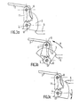
- Figures 3a, 3b and 3c are diagrams showing the successive stages of the operation of closing the door.
- the bolt is oriented facing the keeper according to increasing radii which allows it, after exhaust, to come into abutment under the keeper and thus to block the door (figure 3c).
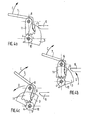
- Figures 4a, 4b and 4c are diagrams showing the successive stages of operation of the locking device when the door is opened.
- the opening of the door is caused by the handle 7 which is pivoted about the axis 8 in the direction of the arrow C, against the force exerted by the handle spring 12, shown in the Figure 2.
- the stop 13 pushes the movable sector 11 rotatably mounted about the axis 8.
- the movable sector 11 cooperates with the pinion 10 of the bolt by means of teeth, and drives said pinion.
- the pinion 10 integral with the bolt pivots in the direction of arrow D and goes against the force exerted by the spring 9 of the bolt.
- the bolt 3, the radius of curvature of which varies discreetly, is oriented in front of the striker according to the decreasing radii, which allows it to be released from below the striker (FIG. 4b).
- the full pivoting of the handle completely releases the bolt from underneath the keeper ( Figure 4c). It is then possible to raise the door 1 of the tank 14.
Landscapes
- Engineering & Computer Science (AREA)
- Mechanical Engineering (AREA)
- Main Body Construction Of Washing Machines And Laundry Dryers (AREA)
Description
- L'invention concerne une machine à laver le linge à chargement par le dessus possédant une porte sensiblement plane qui pivote autour d'un axe horizontal et qui se rabat horizontalement en position fermée, position dans laquelle elle est bloquée par un dispositif mécanique de blocage composé d'un pêne monté sur la porte et d'une gâche solidaire du cadre de porte, l'un des deux composants du dispositif de blocage tournant pour recevoir l'autre. Une telle machine est connue comme en donne un exemple le brevet français n° 2 501 250.
- Le brevet français n° 2 501 250 a pour objet un appareil dans lequel l'ouverture de la porte demeure impossible, quelle que soit la force avec laquelle l'utilisateur tente d'agir sur un verrou, mais cela dans une structure mécanique parfaitement rigide Dans le cas d'une construction en éléments de matière synthétique, moulés, élément possédant de ce fait une flexibilité non négligeable, la gâche tournante et son crochet sont susceptibles de se désolidariser malgré les sécurités envisagées.
- L'invention a pour objet une machine à laver le linge dans laquelle l'ouverture de la porte demeure impossible. Les déformations mécaniques, dues aux vibrations, aux chocs thermiques, et supportées par les éléments de construction en matière synthétique sont récupérés par le pêne. Celui-ci est susceptible de compenser les jeux qui apparaissent entre la porte et le cadre de porte, au cours de l'utilisation et de la vie de la machine.
- L'invention est caractérisée par le fait que le le pêne est un cylindre, dont la section est une courbe fermée et dont le rayon varie de façon discrète dans la zone de coopération avec la gàche, le pêne étant monté à rotation sur la porte autour d'un axe parallèle à sa génératrice et au plan de la porte et rappelé par des moyens élastiques, qui l'orientent, face à la gâche, selon des rayons croissants, le pêne étant entraîné en rotation sous le poids de la porte, à l'en' contre des moyens élastiques pour échapper sous ladite gâche, en position de blocage de la porte, la gâche étant constituée d'une arête parallèle au pêne sur laquelle vient buter le pêne lors de la fermeture de la porte, des moyens de déblocage de la porte étant susceptibles de faire tourner le pêne à l'en'contre de ses moyens élastiques pour son effacement. La surface du pêne peut présenter donc des crans successifs. Lorsque en cours de fonctionnement porte bloqué, le jeu entre la porte et le cadre de porte augmente d'une distance supérieure à la hauteur d'un cran, les moyens élastiques font tourner le pêne de façon à ce que le cran de côte supérieure soit à son tour en contact avec l'arête de la gâche.
- On connait du brevet US n°2 143 575, un système de fermeture pour porte de réfrigérateur dans lequel, le pêne de courbure variable est monté à rotation sur la porte et s'efface sous une gâche, sous l'effet d'un ressort. Toutefois, dans ce brevet US, d'une part, la courbure du pêne est continue, d'autre part la course du pêne entraîné à rotation par un ressort est limitée par butée de la crosse de la barre d'ouverture du pêne contre un épaulement.
- Appliquée à une machine à laver du type de celle de l'invention, une telle fermeture ne peut pas rattraper les jeux importants (plusieurs millimètres dans le cas d'un cadre et d'une porte en matière systhétique) du fait de la limitation du mouvement du pêne. Par ailleurs, les vibrations dûes au fonctionnement de machines à laver et à essorer le linge peuvent provoquer des déplacements du point de contact pêne-gâche, par glissement, si la courbure du pêne varie de façon continue.
- Dans un autre mode préférentiel de réalisation les moyens de déblocage de la porte sont composés d'une part, d'un secteur mobile transversalement au pêne, coopérant avec un pignon solidaire dudit pêne, et d'autre part, d'une poignée pivotant librement par rapport au secteur et susceptible de pousser ledit secteur pour l'entraînement du pêne à l'encontre de ses moyens élastiques. Le système de déblocage, allant à l'encontre des moyens élastiques, fait tourner le pêne de façon à ce que les crans de côte supérieure au cran utilisé soient sollicités à leur tour. Le jeu entre le pêne et l'arête de la gâche augmente alors jusqu'à l'effacement du pêne.
- La description qui suit et les dessins illustrent un mode de réalisation de l'invention.
- La figure 1 représente une vue en perspective d'une porte de machine à laver le linge à chargement par le dessus, en position fermée et son dispositif mécanique de blocage.
- La figure 2 montre le mécanisme de blocage en perspective.
- Les figures 3a, 3b et 3c sont un schéma de principe de fonctionnement du mécanisme de blocage au moment de la fermeture de la porte.
- Les figures 4a, 4b et 4c sont un schéma de principe de fonctionnement du mécanisme de blocage au moment de l'ouverture de la porte.
- La figure 1 représente la zone supérieure d'une machine à laver le linge à chargement par le dessus, dont la cuve 14 est fermée par une porte 1 qui pivote autour de l'axe 2 horizontal et se rabat horizontalement en position fermée, position dans laquelle elle est bloquée par un disposiif mécanique de blocage porté par deux flasques 5 parallèles moulés avec la porte. Un pêne 3 est monté à rotation autour d'un axe 4, qui est parallèle au plan de la porte. Les deux extrémités de l'axe 4 du pêne se logent dans deux trous aménagés dans les flasques 5, support de mécanisme. Le bord de la cuve 14 qui forme, dans cet exemple de réalisation, la gàche 6, est en contact avec le pêne. La poignée 7 est montée à rotation sur un axe 8 parallèle à l'axe 4 du pêne l'axe 8 de poignée se fixe à la porte par ses deux extrémités, qui se logent dans deux trous aménagés dans les flasques 5 support de mécanisme.
- La figure 2 montre le mécanisme de blocage de la porte.
- Le pêne 3, un cylindre ici partiellement représenté, dont la section forme une courbe fermée de rayon variable, est monté à rotation autour de l'axe 4 parallèle à sa génératrice et rappelé-par des moyens élastiques qui, dans cet exemple de réalisation, sont constitués d'un ressort hélicoïdal guidé par l'axe du pêne 4 et travaillant en torsion. Une extrémité du ressort 9 du pêne prend appui sur la porte et l'autre extrémité se loge dans une ' forme de fixation aménagée dans le pêne, forme non représentée sur la figure 2.
- Sur la partie du pêne, et solidaire de celui-ci, est moulé un pignon 10 dont l'axe se confond avec l'axe 4 de rotation du pêne. Le pignon 10 coopère avec un secteur denté mobile 11 pivotant autour de l'axe 8 de poignée. Le secteur mobile 11 est susceptible d'être poussé par une forme moulée 13 de la poignée, faisant butée et entraînant le secteur en rotation. La poignée 7 montée sur son axe 8 possède des moyens élastiques de rappel. Dans cet exemple ces moyens élastiques sont représentés par un ressort hélicoïdal 12 travaillant en traction. Le ressort de poignée 12, est fixé d'une part, à un oeillet moulé avec la poignée 7 de porte et d'autre part, à un oeillet moulé avec la porte elle-même.
- Le dispositif illustré fonctionne de la manière qui suit.
- Les figures 3a, 3b et 3c sont des schémas montrant les étapes successives du fonctionnement de la fermeture de la porte.
- Au moment de la fermeture, la porte 1 (figure 1) se rabat dans une position horizontale. Le pêne vient en appui sur la gâche 6 qui est le bord de la cuve 14. La force du ressort 9 du pêne est choisie telle que le simple poids de la porte fait basculer le pêne 3 dans le sens de la flèche A, à l'encontre de la force exercée par le ressort 9 travaillant en torsion autour de l'axe 4. Le basculement du pêne est rêalisé par un effet de levier dont le point d'appui est la partie supérieure de la gâche (figure 3b). Après l'effet de bas' cule, le pêne s'échappe sous la gâche dans le sens de la flèche B (figure 3c). En effet, le pêne n'étant plus en appui sur la gâche, il pivote sous l'effet de la force exercée par le ressort 9. Le pêne dont le rayon de courbure varie dans ce cas de façon discrète s'oriente face à la gâche selon des rayons croissants ce qui lui permet après échappement de venir en butée sous la gâche et ainsi de bloquer la porte (figure 3c).
- Les figures 4a, 4b et 4c sont des schémas monrant les étapes successives du fonctionnement du dispositif de blocage au moment de l'ouverture de la porte.
- L'ouverture de la porte est provoquée par la poignée 7 que l'on fait pivoter autour de l'axe 8 dans le sens de la flèche C, à l'encontre de la force exercée par le ressort 12 de poignée, représenté sur la figure 2. La butée 13 pousse lé secteur mobile 11 monté à rotation autour de l'axe 8. Le secteur mobile 11 coopère avec le pignon 10 du pêne au moyen de dentures, et entraîne ledit pignon. Le pignon 10, solidaire du pêne pivote dans le sens de la flèche D et va à l'encontre de la force exercée par le ressort 9 du pêne. Le pêne 3 dont le rayon de courbure varie de façon discrète s'oriente face à la gâche selon les rayons décroissants ce qui lui permet de se dégager de dessous la gâche (figure 4b). Le pivotement total de la poignée dégage totalement le pêne de dessous la gâche (figure 4c). Il est alors possible de relever la porte 1 de cuve 14.
Claims (2)
Applications Claiming Priority (2)
| Application Number | Priority Date | Filing Date | Title |
|---|---|---|---|
| FR8320690 | 1983-12-23 | ||
| FR8320690A FR2557161B1 (fr) | 1983-12-23 | 1983-12-23 | Machine a laver et a essorer le linge possedant une porte equipee d'un dispositif mecanique de blocage |
Publications (3)
| Publication Number | Publication Date |
|---|---|
| EP0146996A2 EP0146996A2 (fr) | 1985-07-03 |
| EP0146996A3 EP0146996A3 (en) | 1985-08-14 |
| EP0146996B1 true EP0146996B1 (fr) | 1988-07-13 |
Family
ID=9295508
Family Applications (1)
| Application Number | Title | Priority Date | Filing Date |
|---|---|---|---|
| EP84201898A Expired EP0146996B1 (fr) | 1983-12-23 | 1984-12-18 | Machine à laver le linge possédant une porte équipée d'un dispositif mécanique de blocage |
Country Status (3)
| Country | Link |
|---|---|
| EP (1) | EP0146996B1 (fr) |
| DE (1) | DE3472691D1 (fr) |
| FR (1) | FR2557161B1 (fr) |
Families Citing this family (4)
| Publication number | Priority date | Publication date | Assignee | Title |
|---|---|---|---|---|
| FR2651843B1 (fr) * | 1989-09-12 | 1991-12-20 | Aerospatiale | Systeme de verrouillage a came. |
| FR2862692A1 (fr) * | 2003-11-26 | 2005-05-27 | Michel Bourlon | Dispositif permettant de bloquer une porte ou analogue |
| CN110409141B (zh) * | 2018-04-28 | 2021-08-10 | 无锡小天鹅电器有限公司 | 用于盖体的锁闭装置、洗衣设备的上盖结构及洗衣设备 |
| CN110409133B (zh) * | 2018-04-28 | 2021-08-10 | 无锡小天鹅电器有限公司 | 用于盖体的锁闭装置、洗衣设备的上盖结构及洗衣设备 |
Family Cites Families (5)
| Publication number | Priority date | Publication date | Assignee | Title |
|---|---|---|---|---|
| GB591612A (en) * | 1945-05-14 | 1947-08-22 | Willem Van Leer | Improvements in or relating to door and like latches or catches |
| US2143575A (en) * | 1937-01-09 | 1939-01-10 | Stanley Works | Spring catch |
| US2559736A (en) * | 1945-11-27 | 1951-07-10 | Curtiss Wright Corp | Latch |
| GB1399058A (en) * | 1973-04-07 | 1975-06-25 | Overton Ltd Wilfred | Latches |
| DE3107662C1 (de) * | 1981-02-28 | 1982-12-16 | Häfele KG, 7270 Nagold | Schnappverschluss fuer Schranktueren oder dgl. |
-
1983
- 1983-12-23 FR FR8320690A patent/FR2557161B1/fr not_active Expired
-
1984
- 1984-12-18 EP EP84201898A patent/EP0146996B1/fr not_active Expired
- 1984-12-18 DE DE8484201898T patent/DE3472691D1/de not_active Expired
Also Published As
| Publication number | Publication date |
|---|---|
| FR2557161A1 (fr) | 1985-06-28 |
| FR2557161B1 (fr) | 1986-11-14 |
| EP0146996A2 (fr) | 1985-07-03 |
| DE3472691D1 (en) | 1988-08-18 |
| EP0146996A3 (en) | 1985-08-14 |
Similar Documents
| Publication | Publication Date | Title |
|---|---|---|
| FR2561878A1 (fr) | Dispositif de fermeture, en particulier pour des chaussures de ski a ouverture arriere | |
| FR2720283A1 (fr) | Appareil anti-chute verrouillage automatiquement sur une corde de sécurité. | |
| CH663520A5 (fr) | Chaussure a ouverture arriere, notamment pour la pratique du ski. | |
| EP0017539A1 (fr) | Dispositif de serrure notamment pour valise | |
| CA1265693A (fr) | Dispositif de verrouillage de tampon de regard de chaussee | |
| EP0143705A1 (fr) | Dispositif d'ouverture et de fermeture électrique d'un battant de véhicule muni d'une serrure du type à armement | |
| EP0002396B1 (fr) | Ensemble de crochet de manutention | |
| EP0146996A2 (fr) | Machine à laver le linge possédant une porte équipée d'un dispositif mécanique de blocage | |
| FR2712337A1 (fr) | Dispositif de verrouillage à au moins un point de condamnation. | |
| CA1297135C (fr) | Ferrure de verrouillage notamment pour ouvrant coulissant | |
| FR2721523A1 (fr) | Descendeur à verrouillage de la poulie pour le blocage permanent de la corde. | |
| FR2717210A1 (fr) | Dispositif de verrouillage automatique d'un battant de volet. | |
| EP1057954B1 (fr) | Serrure électromécanique de sécurité | |
| FR2588605A1 (fr) | Systeme manoeuvrable d'arret d'un battant de volet et ensemble de crochetage dudit battant. | |
| EP0696895B1 (fr) | Panier pour appareil de cuisson | |
| FR2641952A1 (fr) | Dispositif de fermeture au moyen d'un levier basculant et coulissant, notamment pour valises | |
| FR2529937A1 (fr) | Dispositif de fermeture a pene profile enveloppant rotatif et a gache rentrante | |
| FR2490689A1 (fr) | Dispositif d'immobilisation temporaire d'un tambour de machine a laver le linge | |
| FR2681368A1 (fr) | Dispositif de fermeture pour porte retournable, et armoire dont la porte est equipee d'un tel dispositif de fermeture, notamment pour appareillages electriques . | |
| FR2656372A1 (fr) | Mecanisme de verrouillage d'un store mecanique. | |
| FR2694782A1 (fr) | Loquet basculant pour vantail. | |
| FR2777312A1 (fr) | Poignee pour ouverture et fermeture de volet battant | |
| FR2644101A1 (fr) | Dispositif de fermeture pour porte de presse a balles | |
| EP1718827B1 (fr) | Barre anti-panique et porte ainsi équipée | |
| FR2685378A1 (fr) | Agencement de verrouillage notamment antipanique d'un organe mobile de fermeture d'une ouverture, tel qu'une porte. |
Legal Events
| Date | Code | Title | Description |
|---|---|---|---|
| PUAI | Public reference made under article 153(3) epc to a published international application that has entered the european phase |
Free format text: ORIGINAL CODE: 0009012 |
|
| PUAL | Search report despatched |
Free format text: ORIGINAL CODE: 0009013 |
|
| AK | Designated contracting states |
Designated state(s): DE FR GB IT |
|
| AK | Designated contracting states |
Designated state(s): DE FR GB IT |
|
| 17P | Request for examination filed |
Effective date: 19860210 |
|
| 17Q | First examination report despatched |
Effective date: 19870227 |
|
| GRAA | (expected) grant |
Free format text: ORIGINAL CODE: 0009210 |
|
| AK | Designated contracting states |
Kind code of ref document: B1 Designated state(s): DE FR GB IT |
|
| ITF | It: translation for a ep patent filed | ||
| REF | Corresponds to: |
Ref document number: 3472691 Country of ref document: DE Date of ref document: 19880818 |
|
| GBT | Gb: translation of ep patent filed (gb section 77(6)(a)/1977) | ||
| REG | Reference to a national code |
Ref country code: FR Ref legal event code: TP |
|
| REG | Reference to a national code |
Ref country code: GB Ref legal event code: 732 |
|
| PLBE | No opposition filed within time limit |
Free format text: ORIGINAL CODE: 0009261 |
|
| STAA | Information on the status of an ep patent application or granted ep patent |
Free format text: STATUS: NO OPPOSITION FILED WITHIN TIME LIMIT |
|
| 26N | No opposition filed | ||
| REG | Reference to a national code |
Ref country code: FR Ref legal event code: TP |
|
| ITPR | It: changes in ownership of a european patent |
Owner name: CESSIONE;WHIRLPOOL INTERNATIONAL B.V. |
|
| REG | Reference to a national code |
Ref country code: FR Ref legal event code: CD |
|
| ITTA | It: last paid annual fee | ||
| PGFP | Annual fee paid to national office [announced via postgrant information from national office to epo] |
Ref country code: GB Payment date: 19961209 Year of fee payment: 13 |
|
| PGFP | Annual fee paid to national office [announced via postgrant information from national office to epo] |
Ref country code: FR Payment date: 19961211 Year of fee payment: 13 |
|
| PGFP | Annual fee paid to national office [announced via postgrant information from national office to epo] |
Ref country code: DE Payment date: 19970220 Year of fee payment: 13 |
|
| PG25 | Lapsed in a contracting state [announced via postgrant information from national office to epo] |
Ref country code: GB Free format text: LAPSE BECAUSE OF NON-PAYMENT OF DUE FEES Effective date: 19971218 |
|
| PG25 | Lapsed in a contracting state [announced via postgrant information from national office to epo] |
Ref country code: FR Free format text: THE PATENT HAS BEEN ANNULLED BY A DECISION OF A NATIONAL AUTHORITY Effective date: 19971231 |
|
| GBPC | Gb: european patent ceased through non-payment of renewal fee |
Effective date: 19971218 |
|
| PG25 | Lapsed in a contracting state [announced via postgrant information from national office to epo] |
Ref country code: DE Free format text: LAPSE BECAUSE OF NON-PAYMENT OF DUE FEES Effective date: 19980901 |
|
| REG | Reference to a national code |
Ref country code: FR Ref legal event code: ST |