EP0147038A1 - Jaugeurs de niveau du liquide - Google Patents
Jaugeurs de niveau du liquide Download PDFInfo
- Publication number
- EP0147038A1 EP0147038A1 EP84307644A EP84307644A EP0147038A1 EP 0147038 A1 EP0147038 A1 EP 0147038A1 EP 84307644 A EP84307644 A EP 84307644A EP 84307644 A EP84307644 A EP 84307644A EP 0147038 A1 EP0147038 A1 EP 0147038A1
- Authority
- EP
- European Patent Office
- Prior art keywords
- light
- gauge
- water
- liquid level
- steam
- Prior art date
- Legal status (The legal status is an assumption and is not a legal conclusion. Google has not performed a legal analysis and makes no representation as to the accuracy of the status listed.)
- Granted
Links
Images
Classifications
-
- G—PHYSICS
- G01—MEASURING; TESTING
- G01F—MEASURING VOLUME, VOLUME FLOW, MASS FLOW OR LIQUID LEVEL; METERING BY VOLUME
- G01F23/00—Indicating or measuring liquid level or level of fluent solid material, e.g. indicating in terms of volume or indicating by means of an alarm
- G01F23/22—Indicating or measuring liquid level or level of fluent solid material, e.g. indicating in terms of volume or indicating by means of an alarm by measuring physical variables, other than linear dimensions, pressure or weight, dependent on the level to be measured, e.g. by difference of heat transfer of steam or water
- G01F23/28—Indicating or measuring liquid level or level of fluent solid material, e.g. indicating in terms of volume or indicating by means of an alarm by measuring physical variables, other than linear dimensions, pressure or weight, dependent on the level to be measured, e.g. by difference of heat transfer of steam or water by measuring the variations of parameters of electromagnetic or acoustic waves applied directly to the liquid or fluent solid material
- G01F23/284—Electromagnetic waves
- G01F23/292—Light, e.g. infrared or ultraviolet
-
- G—PHYSICS
- G01—MEASURING; TESTING
- G01F—MEASURING VOLUME, VOLUME FLOW, MASS FLOW OR LIQUID LEVEL; METERING BY VOLUME
- G01F23/00—Indicating or measuring liquid level or level of fluent solid material, e.g. indicating in terms of volume or indicating by means of an alarm
- G01F23/02—Indicating or measuring liquid level or level of fluent solid material, e.g. indicating in terms of volume or indicating by means of an alarm by gauge glasses or other apparatus involving a window or transparent tube for directly observing the level to be measured or the level of a liquid column in free communication with the main body of the liquid
Definitions
- This invention relates to liquid level gauges, for instance gauges for determining the level of water and/or steam in - for instance - a boiler.
- a liquid level gauge of the Blackburn type comprising a body member having front and rear windows and a light refracting fluid passage therethrough connecting the front and rear windows, one or more light sources provided adjacent the rear window, a condensing lens interposed between the one or more light sources and the rear window to direct a beam of light from the one or more light sources through the rear window into the light refracting fluid passage, and a set of optical fibres provided adjacent the front window to intercept the light beam as it exits from the light refracting fluid passage and provide an indication as to the presence or absence of liquid in the light refracting fluid passage.
- a preferred embodiment of the present invention described in detail below solves or at least alleviates the aforementioned problem associated with the prior art by utilising optical fibres which are positioned to intercept the light that passes in a relatively straight path through a cross passage in the body of the gauge of the Blackburn type. Because of the relatively low index of refraction of steam as compared to that of water, the optical fibres intercept light when steam is present in the body of the gauge, permitting the actuation of a sensing device to indicate the presence of steam. In contrast, when water is present in the body of the gauge, the light is refracted away from the optical fibres, resulting in the sensing device remaining unactuated. Redundant light sources are provided to ensure the presence of light in the cross passage provided in the body of the gauge. Optical fibres are also present adjacent each light source to intercept the light produced by the light sources and thus provide an indication to another sensing device that a light source is illuminated at all times.
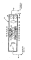
- the single figure of the drawing is a cross-sectional view of a liquid level gauge 10 embodying the invention. It should be noted that the Blackburn principle is adhered to in practicing the present invention.
- the gauge 10 has a body 12 preferably formed of metal so as to have sufficient strength to withstand the designed pressure.
- the body 12 has a generally trapezoidal cross-section and has a vertical water passage 14 formed therein.
- a horizontal cross passage 16 extends through the central portion of the body 12 so as to intersect the axis of the water passage 14 and terminates in counterbored openings 18, 20 provided in front and rear faces 22, 24, respectively, of the body 12.
- the front counterbored opening 18 is positioned so that its axis is perpendicular to the front face 22 of the body 12, and the rear counterbored opening 20 is positioned so that its axis is perpendicular to the rear face 24 of the body 12.
- a sealing gasket 26, a mica shield 28 and a port glass 30 are provided in each of the counterbored openings 18, 20 and are retained therein by a front clamping plate 32 and a rear clamping plate 34 which are attached by bolts which engage threaded holes in the front face 22 and the rear face 24, respectively, or by other suitable attachment means.
- the clamping plates 32, 34 form viewing ports through which the prismatic chamber defined by the internal area between the port glasses 30 can be viewed.
- the water passage 14 is capable of being connected at its upper end to the steam space located within the upper portion of a steam drum of a boiler, and of being connected at its lower end to the water space within the boiler. In this manner either water or steam will be observed, depending upon the water level within the boiler, when the prismatic chamber is viewed through the viewing ports.
- a plurality of light sources 36 are located adjacent a rear wall of the gauge 10.
- An optical condensing lens 38 is interposed between the plurality of light sources 36 and the rear face 24 of the body 12. The condensing lens 38 is utilised to project a columnar beam of light from each of the light sources 36 into the water passage 14 via the rear counterbored opening 20.
- An optical fibre 40 is positioned adjacent each of the light sources 36 and passes through the rear wall of the gauge 10 for connection to a sensing device (not shown) which determines whether each of the light sources 36 is illuminated.
- An optical condensing lens 42 is interposed between the front face 22 of the body 12 and the front wall of the gauge 10, and is utilised to form the light which passes through the horizontal cross passage 16 into a columnar light beam and project the beam against a front wall of the gauge 10.
- a multiple optical fibre cable 44 is located adjacent the front wall of the gauge 10 and is positioned so as to intercept the beam of light produced by and exiting from the condensing lens 42.
- the optical fibres 44 pass through the front wall of the gauge 10 and are connected to a sensing device (not shown) which senses whether light is being transmitted through the body 12. This latter sensing device and the former sensing device for the light sources 36 can be located at a location remote from the hostile environment in which the gauge 10 is installed.
- the light which is directed into the cross passage 16 when steam is present in the water passage 14 will pass in a relative straight path therethrough to the optical fibres 44 which, in turn, cause the sensing device associated therewith to sense that light is being transmitted through the body 12 to the fibres 44 and thus that steam is present in the water passage 14.
- the sensing device associated therewith senses that light is being transmitted through the body 12 to the fibres 44 and thus that steam is present in the water passage 14.
- the light which is directed into the cross passage 16 is refracted laterally because of the greater index of refraction of water. Because of this, the light beam produced by the condensing lens 42 is refracted and does not intercept the optical fibres 44. In this manner, the sensing device associated with the fibres 44 is not actuated, thus indicating that water is present in the water passage 14.
- a plurality of gauges 10 can be arranged in a stacked relationship and that the water passages 14 can be fluidically inter-connected so that the level of steam and/or water within a boiler can be determined incrementally. In this manner, an accurate indication of the level of steam and/or water within a boiler can be obtained.
Landscapes
- Physics & Mathematics (AREA)
- Electromagnetism (AREA)
- Fluid Mechanics (AREA)
- General Physics & Mathematics (AREA)
- Thermal Sciences (AREA)
- Measurement Of Levels Of Liquids Or Fluent Solid Materials (AREA)
- Level Indicators Using A Float (AREA)
- Golf Clubs (AREA)
- Electromechanical Clocks (AREA)
- Manufacturing Of Printed Circuit Boards (AREA)
- Electrical Discharge Machining, Electrochemical Machining, And Combined Machining (AREA)
- Investigating Or Analysing Materials By Optical Means (AREA)
Priority Applications (1)
| Application Number | Priority Date | Filing Date | Title |
|---|---|---|---|
| AT84307644T ATE40204T1 (de) | 1983-12-23 | 1984-11-06 | Fluessigkeitsstandanzeiger. |
Applications Claiming Priority (2)
| Application Number | Priority Date | Filing Date | Title |
|---|---|---|---|
| US56494183A | 1983-12-23 | 1983-12-23 | |
| US564941 | 1983-12-23 |
Publications (2)
| Publication Number | Publication Date |
|---|---|
| EP0147038A1 true EP0147038A1 (fr) | 1985-07-03 |
| EP0147038B1 EP0147038B1 (fr) | 1989-01-18 |
Family
ID=24256530
Family Applications (1)
| Application Number | Title | Priority Date | Filing Date |
|---|---|---|---|
| EP84307644A Expired EP0147038B1 (fr) | 1983-12-23 | 1984-11-06 | Jaugeurs de niveau du liquide |
Country Status (7)
| Country | Link |
|---|---|
| EP (1) | EP0147038B1 (fr) |
| JP (2) | JPS60135824A (fr) |
| AT (1) | ATE40204T1 (fr) |
| CA (1) | CA1222395A (fr) |
| DE (1) | DE3476262D1 (fr) |
| MX (1) | MX157492A (fr) |
| ZA (1) | ZA847889B (fr) |
Cited By (1)
| Publication number | Priority date | Publication date | Assignee | Title |
|---|---|---|---|---|
| ES2555327R1 (es) * | 2013-04-30 | 2016-01-29 | Acciona Agua, S.A. | Dispositivo de control del nivel de lodos en decantadores de lamelas |
Families Citing this family (1)
| Publication number | Priority date | Publication date | Assignee | Title |
|---|---|---|---|---|
| JPH0435773Y2 (fr) * | 1987-11-13 | 1992-08-25 |
Citations (3)
| Publication number | Priority date | Publication date | Assignee | Title |
|---|---|---|---|---|
| US3713338A (en) * | 1971-01-18 | 1973-01-30 | Gen Motors Corp | Fiber optic liquid level indicator |
| US4217778A (en) * | 1978-10-23 | 1980-08-19 | The Babcock & Wilcox Company | Liquid level gauge illuminating system |
| EP0061334A1 (fr) * | 1981-03-23 | 1982-09-29 | The Babcock & Wilcox Company | Assemblage des jauges de niveau de liquide pour l'indication à distance et locale de niveau de liquide |
Family Cites Families (1)
| Publication number | Priority date | Publication date | Assignee | Title |
|---|---|---|---|---|
| DE2920199A1 (de) * | 1978-05-31 | 1979-12-06 | Eaton Sa Monaco | Fluessigkeitsniveau-anzeigevorrichtung |
-
1984
- 1984-10-09 ZA ZA847889A patent/ZA847889B/xx unknown
- 1984-10-09 JP JP59210630A patent/JPS60135824A/ja active Pending
- 1984-10-19 MX MX203111A patent/MX157492A/es unknown
- 1984-11-06 EP EP84307644A patent/EP0147038B1/fr not_active Expired
- 1984-11-06 DE DE8484307644T patent/DE3476262D1/de not_active Expired
- 1984-11-06 AT AT84307644T patent/ATE40204T1/de not_active IP Right Cessation
- 1984-11-07 CA CA000467252A patent/CA1222395A/fr not_active Expired
-
1990
- 1990-10-08 JP JP1990105302U patent/JPH0338656Y2/ja not_active Expired
Patent Citations (3)
| Publication number | Priority date | Publication date | Assignee | Title |
|---|---|---|---|---|
| US3713338A (en) * | 1971-01-18 | 1973-01-30 | Gen Motors Corp | Fiber optic liquid level indicator |
| US4217778A (en) * | 1978-10-23 | 1980-08-19 | The Babcock & Wilcox Company | Liquid level gauge illuminating system |
| EP0061334A1 (fr) * | 1981-03-23 | 1982-09-29 | The Babcock & Wilcox Company | Assemblage des jauges de niveau de liquide pour l'indication à distance et locale de niveau de liquide |
Cited By (1)
| Publication number | Priority date | Publication date | Assignee | Title |
|---|---|---|---|---|
| ES2555327R1 (es) * | 2013-04-30 | 2016-01-29 | Acciona Agua, S.A. | Dispositivo de control del nivel de lodos en decantadores de lamelas |
Also Published As
| Publication number | Publication date |
|---|---|
| CA1222395A (fr) | 1987-06-02 |
| JPS60135824A (ja) | 1985-07-19 |
| JPH0338656Y2 (fr) | 1991-08-15 |
| MX157492A (es) | 1988-11-25 |
| ATE40204T1 (de) | 1989-02-15 |
| EP0147038B1 (fr) | 1989-01-18 |
| JPH0357633U (fr) | 1991-06-04 |
| DE3476262D1 (en) | 1989-02-23 |
| ZA847889B (en) | 1985-07-31 |
Similar Documents
| Publication | Publication Date | Title |
|---|---|---|
| US4440022A (en) | Liquid-level detection | |
| US4450722A (en) | Water level gauge with fault detector | |
| US2240988A (en) | Liquid level indicator | |
| US6894778B2 (en) | Low detection limit turbidimeter | |
| US4633711A (en) | Local display technique for fiber optic illuminator/hood system | |
| US5072616A (en) | Fiber optic level alarm | |
| EP0147038A1 (fr) | Jaugeurs de niveau du liquide | |
| EP0355134B1 (fr) | Detecteur optique du niveau d'un fluide | |
| CA1174874A (fr) | Indicateur de niveau d'eau a lecture locale et a distance | |
| CA1112082A (fr) | Systeme d'eclairage sur indicateur de niveau de liquide | |
| US470858A (en) | Richard klinger | |
| US2949031A (en) | Multi-port liquid level gauge | |
| US1532995A (en) | Level indicator of the luminous type | |
| CA1190762A (fr) | Indicateur de niveau a fibre optique, et dome de soupape qui en est garni, pour cuves sous pression | |
| US2369798A (en) | Water gauge | |
| GB2076960A (en) | Liquid sensor | |
| US4624567A (en) | Fluid particle sensor | |
| RU2266525C2 (ru) | Сигнализатор уровня жидкости | |
| US4813759A (en) | Fiber optic high and low level alarms | |
| US3435681A (en) | Liquid level gage | |
| US2351100A (en) | Prismatic accumulator gauge | |
| LU103097B1 (en) | Optical fluid verification for air bubble detection in fluid filled hoses | |
| CN115435867B (zh) | 一种玻璃板液位计以及液位测量方法 | |
| JPS61165625A (ja) | 液面計 | |
| US2174700A (en) | Liquid level indicator |
Legal Events
| Date | Code | Title | Description |
|---|---|---|---|
| PUAI | Public reference made under article 153(3) epc to a published international application that has entered the european phase |
Free format text: ORIGINAL CODE: 0009012 |
|
| AK | Designated contracting states |
Designated state(s): AT BE CH DE FR GB IT LI LU NL SE |
|
| 17P | Request for examination filed |
Effective date: 19851126 |
|
| 17Q | First examination report despatched |
Effective date: 19870619 |
|
| ITF | It: translation for a ep patent filed | ||
| GRAA | (expected) grant |
Free format text: ORIGINAL CODE: 0009210 |
|
| AK | Designated contracting states |
Kind code of ref document: B1 Designated state(s): AT BE CH DE FR GB IT LI LU NL SE |
|
| REF | Corresponds to: |
Ref document number: 40204 Country of ref document: AT Date of ref document: 19890215 Kind code of ref document: T |
|
| REF | Corresponds to: |
Ref document number: 3476262 Country of ref document: DE Date of ref document: 19890223 |
|
| ET | Fr: translation filed | ||
| PLBE | No opposition filed within time limit |
Free format text: ORIGINAL CODE: 0009261 |
|
| STAA | Information on the status of an ep patent application or granted ep patent |
Free format text: STATUS: NO OPPOSITION FILED WITHIN TIME LIMIT |
|
| 26N | No opposition filed | ||
| PGFP | Annual fee paid to national office [announced via postgrant information from national office to epo] |
Ref country code: GB Payment date: 19911017 Year of fee payment: 8 |
|
| PGFP | Annual fee paid to national office [announced via postgrant information from national office to epo] |
Ref country code: SE Payment date: 19911022 Year of fee payment: 8 |
|
| PGFP | Annual fee paid to national office [announced via postgrant information from national office to epo] |
Ref country code: AT Payment date: 19911029 Year of fee payment: 8 |
|
| PGFP | Annual fee paid to national office [announced via postgrant information from national office to epo] |
Ref country code: FR Payment date: 19911120 Year of fee payment: 8 |
|
| PGFP | Annual fee paid to national office [announced via postgrant information from national office to epo] |
Ref country code: DE Payment date: 19911128 Year of fee payment: 8 |
|
| ITTA | It: last paid annual fee | ||
| PGFP | Annual fee paid to national office [announced via postgrant information from national office to epo] |
Ref country code: NL Payment date: 19911130 Year of fee payment: 8 |
|
| PGFP | Annual fee paid to national office [announced via postgrant information from national office to epo] |
Ref country code: BE Payment date: 19911217 Year of fee payment: 8 |
|
| PGFP | Annual fee paid to national office [announced via postgrant information from national office to epo] |
Ref country code: CH Payment date: 19920113 Year of fee payment: 8 |
|
| PG25 | Lapsed in a contracting state [announced via postgrant information from national office to epo] |
Ref country code: LU Free format text: LAPSE BECAUSE OF NON-PAYMENT OF DUE FEES Effective date: 19921106 Ref country code: AT Effective date: 19921106 Ref country code: GB Effective date: 19921106 |
|
| PG25 | Lapsed in a contracting state [announced via postgrant information from national office to epo] |
Ref country code: SE Effective date: 19921107 |
|
| PG25 | Lapsed in a contracting state [announced via postgrant information from national office to epo] |
Ref country code: CH Effective date: 19921130 Ref country code: BE Effective date: 19921130 Ref country code: LI Effective date: 19921130 |
|
| PGFP | Annual fee paid to national office [announced via postgrant information from national office to epo] |
Ref country code: LU Payment date: 19921231 Year of fee payment: 8 |
|
| EPTA | Lu: last paid annual fee | ||
| BERE | Be: lapsed |
Owner name: THE BABCOCK & WILCOX CY Effective date: 19921130 |
|
| PG25 | Lapsed in a contracting state [announced via postgrant information from national office to epo] |
Ref country code: NL Effective date: 19930601 |
|
| GBPC | Gb: european patent ceased through non-payment of renewal fee |
Effective date: 19921106 |
|
| NLV4 | Nl: lapsed or anulled due to non-payment of the annual fee | ||
| PG25 | Lapsed in a contracting state [announced via postgrant information from national office to epo] |
Ref country code: FR Effective date: 19930730 |
|
| REG | Reference to a national code |
Ref country code: CH Ref legal event code: PL |
|
| PG25 | Lapsed in a contracting state [announced via postgrant information from national office to epo] |
Ref country code: DE Effective date: 19930803 |
|
| REG | Reference to a national code |
Ref country code: FR Ref legal event code: ST |
|
| EUG | Se: european patent has lapsed |
Ref document number: 84307644.9 Effective date: 19930610 |
|
| PG25 | Lapsed in a contracting state [announced via postgrant information from national office to epo] |
Ref country code: LU Free format text: LAPSE BECAUSE OF NON-PAYMENT OF DUE FEES Effective date: 19911130 |