EP0147059A2 - Gurtklemmvorrichtung - Google Patents
Gurtklemmvorrichtung Download PDFInfo
- Publication number
- EP0147059A2 EP0147059A2 EP84308121A EP84308121A EP0147059A2 EP 0147059 A2 EP0147059 A2 EP 0147059A2 EP 84308121 A EP84308121 A EP 84308121A EP 84308121 A EP84308121 A EP 84308121A EP 0147059 A2 EP0147059 A2 EP 0147059A2
- Authority
- EP
- European Patent Office
- Prior art keywords
- clamping
- guide member
- strap
- axis
- angular movement
- Prior art date
- Legal status (The legal status is an assumption and is not a legal conclusion. Google has not performed a legal analysis and makes no representation as to the accuracy of the status listed.)
- Granted
Links
Images


Classifications
-
- B—PERFORMING OPERATIONS; TRANSPORTING
- B60—VEHICLES IN GENERAL
- B60R—VEHICLES, VEHICLE FITTINGS, OR VEHICLE PARTS, NOT OTHERWISE PROVIDED FOR
- B60R22/00—Safety belts or body harnesses in vehicles
- B60R22/18—Anchoring devices
- B60R22/185—Anchoring devices with stopping means for acting directly upon the belt in an emergency, e.g. by clamping or friction
- B60R22/1855—Anchoring devices with stopping means for acting directly upon the belt in an emergency, e.g. by clamping or friction the means being sensitive to belt tension
-
- A—HUMAN NECESSITIES
- A44—HABERDASHERY; JEWELLERY
- A44B—BUTTONS, PINS, BUCKLES, SLIDE FASTENERS, OR THE LIKE
- A44B13/00—Hook or eye fasteners
-
- B—PERFORMING OPERATIONS; TRANSPORTING
- B60—VEHICLES IN GENERAL
- B60R—VEHICLES, VEHICLE FITTINGS, OR VEHICLE PARTS, NOT OTHERWISE PROVIDED FOR
- B60R22/00—Safety belts or body harnesses in vehicles
- B60R22/18—Anchoring devices
- B60R22/20—Anchoring devices adjustable in position, e.g. in height
- B60R22/201—Anchoring devices adjustable in position, e.g. in height with the belt anchor connected to a slider movable in a vehicle-mounted track
- B60R22/202—Anchoring devices adjustable in position, e.g. in height with the belt anchor connected to a slider movable in a vehicle-mounted track the slider comprising spring-actuated locking means
- B60R22/203—Anchoring devices adjustable in position, e.g. in height with the belt anchor connected to a slider movable in a vehicle-mounted track the slider comprising spring-actuated locking means the locking means being movably mounted on the slider
Definitions
- This invention relates to clamping means for a strap and has particular application to the provision of clamping means for a vehicle safety belt system incorporating an emergency locking refractor.
- Locking mechanisms for safety belt retractors commonly operate to lock the spindle of the retractor. With this arrangement it is usual to find that an undesirably large length of webbing is paid out after the spindle has locked, due to tightening of the coils of webbing wound on the spindle. In addition, it is necessary for the retractor to be strong enough to take full crash load.
- Various proposals have been made for clamping the strap or webbing directly but these have in general been cumbersome and bulky.
- the present invention aims to provide clamping means of this type suitable for use at the shoulder anchorage of a vehicle safety belt system.
- clamping means for a strap comprises a guide member pivotally mounted on a base member for angular movement about a first axis, a clamping member pivotally mounted on the base member for angular movement about a second axis parallel to the first axis and located at a greater radius from the second axis than that of the guide member from the first axis, resilient means for biasing the guide member and the clamping member into a rest position in which the strap is freely movable between the guide member and clamping member, and coupling means arranged so that angular movement of the guide member against the bias of the resilient means towards the plane containing the two pivot axes causes corresponding angular movement of the clamping member, thereby wrapping the strap round both the clamping member and the guide member.
- the clamping means may be mounted in a vehicle adjacent to the shoulder of the user of the safety belt.
- the shoulder strap of the safety belt travels over the guide member and then down past the clamping member on to an emergency locking retractor.
- the strength of the resilient means is arranged to be sufficient to prevent tension in the strap due to the retraction spring of the retractor causing movement of the guide member away from its rest position.
- the retractor locks, the force exerted by the strap on the guide member causes angular movement of the latter away from its rest position and the coupling means causes movement of the clamping member in the same direction.
- the clamping member moves under the guide member, wrapping the strap round the bottom of the latter and the top of itself with the result that the guide member and clamping member are firmly secured together independently of the coupling means. Further angular movement due to the pull exerted on the shoulder strap results in the path of the strap which is in contact with the clamping member coming into face-to-face engagement with the part of the strap leading from the guide member to the shoulder of the user, thereby further increasing the clamping effect.
- the resilient means pushes the guide member and clamping member back to their rest position.
- the clamping means is so arranged that, during all stages of its movement from the fully released to the fully clamped position, no webbing is drawn in by the clamping means as clamping progresses.
- This avoids both the imposition of excess loads on the retractor and any possibility of the retractor itself restricting movement of the clamping means to the fully clamped position.
- One way of achieving this result is to ensure that the clamping member and the guide member are held spaced apart from one another by a controlled distance which reduces progressively as clamping proceeds. This may be achieved by arranging for the radius of either the clamping member or the guide member from its respective pivot axis to change during angular movement thereof from the released to the clamped position.
- the clamping means is pivotally mounted on the vehicle body for angular movement about a horizontal transverse axis relative to the vehicle.
- the clamping means pivots about the horizontal transverse axis so as to take up an angle approximately bisecting the angle between the part of the strap extending towards the retractor and the part of the strap extending towards the shoulder of the user when the belt is in use, the guide member thus being parallel to the fold line of the strap.
- the clamping means may he rigidly secured to the vehicle body.
- the guide member and clamping member may both be straight and disposed parallel to one another.
- the guide member and clamping member may both be of arcuate shape, of approximately the same radius and centred on a point above their two axes.
- the coupling means may take the form of projections on the guide member having cam surfaces which engage with the opposite side of the clamping member to that past which the strap extends.
- the clamping means may be secured to, or formed intergrally with, a traveller which is slidably mounted on a vertically extending track secured to the vehicle body.
- the traveller carries a pivotally mounted lever having a manually operable pushbutton on one side of the pivot and a latch member on the other, the latch member being movable by means of the lever between a position of engagement with a selected one of a row of latching formations on the track and a position of disengagement therefrom.
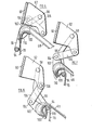
- a vertically extending track 10 is secured to the interior of the B-post 12 on the righthand side of a motor vehicle.
- the track 10 has two side flanges 14 and 16 which are spaced from the B-post 12 and each of which contains a row of uniformly spaced holes 18, 20.
- a metal plate 22 has its sides bent back on themselves so as to form two mutually confronting channel formations 24 and 26 which embrace the edges of the flanges 14 and 16 of the track so that the plate 22 is slidable therealong in the vertical direction but is held captive thereon against horizontal displacement.
- a bridge member 28 is secured to the outsides of the channels 24 and 26 so as to extend across the plate 22 on the opposite side of the track 10.
- Two bolts 30 and 32 are mounted in respective pairs of aligned holes in the bridge member and the plate 22, for movement into and out of engagement with a selective pair of holes 18, 20 in the flanges 14 and 16 of the track 10 so as to prevent movement therealong of the plate 22.
- Each of the bolts 30 and 32 has a notch 34, 36 in its lower surface for receiving the edge of a lever 38 which is pivotally mounted on lugs projecting from the plate 22 by a pivot pin 40.
- a push button 42 is mounted on the lower end of the lever 38.
- a compression spring 44 engages between the plate 22 and the lever 38 behind the push button 42 so as to urge the lower end of the lever 38 outwardly and thus push the bolts 30 and 32 into engagement with the track. Assuming that the bolts 30 and 32 are aligned with one of the pairs of holes 18, 20, the plate 22 is imised on the track. In order to adjust its vertical position, the user merely has to depress the push button 42, thereby disengaging the bolts 30 and 32 and allowing the plate 22 to slide along the track.
- the bottom part 50 of the plate 22 is bent outwardly along an oblique fold line 52, the direction of inclination of the fold line 52, as illustrated in Figures 1 and 2, being that which is appropriate for the left-hand side of a motor vehicle.
- the part 52 has two upturned lugs 54 and 56 forming a first pivot axis, and an outwardly projecting part 58 which carries a pivot pin 60, forming a second pivot axis on its outer end.
- a guide member 62 has side limbs 64 and 66 which are pivotally mounted on the pin 60.
- the guide member 62 is of arcuate shape, centred on a point above the bolt 18 and its upper surface is rounded across its width as can best be seen in Figure 3o
- Part 68 of the shoulder strap of a vehicle safety belt extends from the user's shoulder to the guide member 62 and another part 70 thereof extends downwardly to an emergency locking retractor (not shown).
- An annular clamping member 72 has an arcuate clamping portion 74, of somewhat larger radius than the guide member 62, which is connected by side limbs 76 and 78 to a straight portion 80 uhich rests in the lugs 54 and 56.
- a spring 82 biases the clamping member 72 in the anti-clockwise direction as viewed in Figure 3.
- the guide member 62 has a respective cam projection 84, 86 on each end. Each such cam projection engages with a respective side limb 76, 78 of the clamping member 74, with the result that the spring 82 also biases the guide member 62 in the anti-clockwise direction as viewed in Figure 3. In this position, the clamping member 72 may touch the part 70 of the strap but does not significantly affect the frictional resistance to the strap passing round the guide member 62.
- the strap In use, provided that the tension in the two strap parts 68 and 70 is insufficient to overcome the spring 82, the strap can pass freely over the guide member 62. However, if the tension in the strap increases to such an extent that it moves the guide member 62 in an anti-clockwise direction, as viewed in Figure 3, the engagement between the cam projections 84 and 86 on the one hand and the clamping member 72 on the other causes the latter to move in an anti-clockwise direction, lifting the part 70 of the strap towards the part 68, as shown in Figure 4.
- the safety belt strap is paid out during the early stages of movement from the release position illustrated in Figure 3 to the fully clamped position illustrated in Figure 5, due to the downward movement of the guide member 62 and clamping member 70.
- the geometry of a particular installation was such as to involve further upward movement of the clamping member 72, such upward movement would be resisted by tension in the part 70 of the strap.
- the part 70 can stretch and webbing can be compacted on the retractor spool, the result is to impose an unnecessary load on the retractor and its mountings.
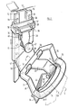
- Figures 6 to 8 illustrate clamping means which is not subject to this disadvantage.
- the shoulder anchorage illustrated in Figure 6 comprises a ⁇ -shaped frame 90 which is intended to be bolted directly on to the B-post (not shown) of a motor vehicle.
- the frame 90 has side limbs 92 and a clamping member 94, the side limbs 96 of which carry respective pivot pins 98 which engage in the side limbs 92 of the frame 90.
- a guide member 100 is mounted on side limbs 102, each of which is pivotally connected, at 104 to a respective link 106.
- Each of the links 106 carries a respective pin 108 which engages in a corresponding side limb 92 of the U-shaped frame 90.
- a spring biases the links 106 in the anti-clockwise direction, as viewed in Figure 6: As with the embodiment illustrated in Figures 1 to 5, part 68 of the shoulder strap of a vehicle safety belt extends from the user's shoulder to the guide member 100 and another part 70 thereof extends downwardly to an emergency locking retractor (not shown).
- the side limbs 102 which support the guide member 100 have projections carrying respective camming surfaces 110 which come into engagement with the clamping member 94, as will be explained hereinafter.
- the strap In use, provided that the tension in the two strap parts 68 and 70 is insufficient to overcome the biasing spring (not shown) for the links 106, the strap can pass freely over the guide member 100. However;, if the tension in the strap increases to such an extent that it moves the guide member 100 downwardly, the camming surfaces 110 come into engagement with the clamping member 94.
- Clamping means of the type illustrated in Figures 6 to 8 may be mounted on height adjustment means as illustrated in Figures 1 and 2.
- clamping means of the type illustrated in Figures 1 to 5 may be adapted to be bolted directly on to a B-post of a motor vehicle.
Landscapes
- Engineering & Computer Science (AREA)
- Mechanical Engineering (AREA)
- Automotive Seat Belt Assembly (AREA)
- Clamps And Clips (AREA)
- Buckles (AREA)
Applications Claiming Priority (6)
| Application Number | Priority Date | Filing Date | Title |
|---|---|---|---|
| GB838331980A GB8331980D0 (en) | 1983-11-30 | 1983-11-30 | Clamping for strap |
| GB8331980 | 1983-11-30 | ||
| GB8333476 | 1983-12-15 | ||
| GB838333476A GB8333476D0 (en) | 1983-12-15 | 1983-12-15 | Clamping means for strap |
| GB8405559 | 1984-03-02 | ||
| GB848405559A GB8405559D0 (en) | 1984-03-02 | 1984-03-02 | Clamping means for strap |
Publications (3)
| Publication Number | Publication Date |
|---|---|
| EP0147059A2 true EP0147059A2 (de) | 1985-07-03 |
| EP0147059A3 EP0147059A3 (en) | 1987-01-21 |
| EP0147059B1 EP0147059B1 (de) | 1990-01-31 |
Family
ID=27262227
Family Applications (1)
| Application Number | Title | Priority Date | Filing Date |
|---|---|---|---|
| EP84308121A Expired EP0147059B1 (de) | 1983-11-30 | 1984-11-23 | Gurtklemmvorrichtung |
Country Status (7)
| Country | Link |
|---|---|
| US (1) | US4547018A (de) |
| EP (1) | EP0147059B1 (de) |
| KR (1) | KR850003835A (de) |
| AU (1) | AU569342B2 (de) |
| BR (1) | BR8405968A (de) |
| DE (1) | DE3481185D1 (de) |
| ES (1) | ES282987Y (de) |
Cited By (4)
| Publication number | Priority date | Publication date | Assignee | Title |
|---|---|---|---|---|
| EP0221681A1 (de) * | 1985-10-09 | 1987-05-13 | Electrolux Autoliv AB | Gurtsperrvorrichtung |
| EP0256678A1 (de) * | 1986-08-06 | 1988-02-24 | Electrolux Autoliv AB | Gurtklemmvorrichtung |
| EP0229258A3 (de) * | 1985-11-18 | 1988-08-03 | Firma Griesemer GmbH Metallwaren und Kunststoffverarbeitung | Gurtbandklemmvorrichtung für einen Sicherheitsgurt |
| DE3708564A1 (de) * | 1986-06-05 | 1988-09-29 | Gudrun Schmidt | Hoehenverstellbarer umlenkbeschlag fuer sicherheitsgurte |
Families Citing this family (8)
| Publication number | Priority date | Publication date | Assignee | Title |
|---|---|---|---|---|
| US5286057A (en) * | 1982-09-08 | 1994-02-15 | Forster Lloyd M | Comfort feature |
| DE3412383A1 (de) * | 1984-02-25 | 1985-10-24 | Hans-Hellmut Dipl.-Ing. 2061 Sülfeld Ernst | Umlenkvorrichtung fuer einen sicherheitsgurt mit abgestufter gurtbandklemmung |
| DE3618880A1 (de) * | 1985-06-07 | 1986-12-11 | Takata Corp., Tokio/Tokyo | Einstellbare verankerung fuer einen fahrzeug-sicherheitsgurt |
| US5054815A (en) * | 1990-03-02 | 1991-10-08 | Takata, Inc. | Shoulder belt comfort mechanism |
| FR2660263B1 (fr) * | 1990-03-30 | 1992-07-24 | Ecia Equip Composants Ind Auto | Renvoi de sangle autobloquant pour ceinture de securite. |
| US5603527A (en) * | 1995-05-15 | 1997-02-18 | General Motors Corporation | Shoulder belt mounting assembly |
| JP2940434B2 (ja) * | 1995-05-29 | 1999-08-25 | トヨタ自動車株式会社 | 車両用シートベルト装置の衝突エネルギ吸収構造 |
| JP3497726B2 (ja) * | 1998-03-26 | 2004-02-16 | 本田技研工業株式会社 | シートベルトのタング掛け機構 |
Family Cites Families (10)
| Publication number | Priority date | Publication date | Assignee | Title |
|---|---|---|---|---|
| DE1506019A1 (de) * | 1966-07-27 | 1969-09-04 | Eubank William J | Befestigungsvorrichtung fuer Sicherheitsgurte oder sonstige Gurtbefestigungen |
| SE7500247L (sv) * | 1975-01-10 | 1976-07-12 | Lindblad O L | Avlenkningsanordning for sekerhetsselar |
| US4306735A (en) * | 1976-11-30 | 1981-12-22 | Allied Chemical Corporation | Safety belt clamp apparatus, occupant restraint system and method |
| EP0018122B1 (de) * | 1979-04-03 | 1985-11-13 | Secretary of State for Transport in Her Britannic Majesty's Gov. of the United Kingdom of Great Britain and Northern Ireland | Klemmsperre für Gurtband |
| DE2950443C2 (de) * | 1979-12-14 | 1986-02-20 | TRW Repa GmbH, 7077 Alfdorf | Gurtband-Hemmvorrichtung |
| DE3007986C2 (de) * | 1980-03-01 | 1983-09-15 | Bayerische Motoren Werke AG, 8000 München | Vorrichtung zum Verstellen eines karosseriefest angeordneten Gurtbeschlages |
| US4359237A (en) * | 1980-04-07 | 1982-11-16 | Irvin Industries Inc. | Static belt loop snubber system |
| DE3018309A1 (de) * | 1980-05-13 | 1981-11-19 | Metallwerk Max Brose Gmbh & Co, 8630 Coburg | Lageverstellbare halteeinrichtung fuer einen mitnehmer eines sicherheitsgurtes |
| US4300731A (en) * | 1980-05-22 | 1981-11-17 | General Motors Corporation | Belt roll-up retractor |
| JPS5877761U (ja) * | 1981-11-24 | 1983-05-26 | 日本精工株式会社 | スル−アンカ−取付装置 |
-
1984
- 1984-11-15 US US06/671,577 patent/US4547018A/en not_active Expired - Fee Related
- 1984-11-16 AU AU35607/84A patent/AU569342B2/en not_active Ceased
- 1984-11-23 DE DE8484308121T patent/DE3481185D1/de not_active Expired - Lifetime
- 1984-11-23 EP EP84308121A patent/EP0147059B1/de not_active Expired
- 1984-11-23 BR BR8405968A patent/BR8405968A/pt not_active IP Right Cessation
- 1984-11-28 ES ES1984282987U patent/ES282987Y/es not_active Expired
- 1984-11-30 KR KR1019840007569A patent/KR850003835A/ko not_active Withdrawn
Cited By (7)
| Publication number | Priority date | Publication date | Assignee | Title |
|---|---|---|---|---|
| EP0221681A1 (de) * | 1985-10-09 | 1987-05-13 | Electrolux Autoliv AB | Gurtsperrvorrichtung |
| US4718148A (en) * | 1985-10-09 | 1988-01-12 | Britax (Wingard) Ltd. | Clamping means for a strap |
| AU584243B2 (en) * | 1985-10-09 | 1989-05-18 | Britax (Wingard) Limited | Clamping means for a strap |
| EP0229258A3 (de) * | 1985-11-18 | 1988-08-03 | Firma Griesemer GmbH Metallwaren und Kunststoffverarbeitung | Gurtbandklemmvorrichtung für einen Sicherheitsgurt |
| DE3708564A1 (de) * | 1986-06-05 | 1988-09-29 | Gudrun Schmidt | Hoehenverstellbarer umlenkbeschlag fuer sicherheitsgurte |
| EP0256678A1 (de) * | 1986-08-06 | 1988-02-24 | Electrolux Autoliv AB | Gurtklemmvorrichtung |
| US4838388A (en) * | 1986-08-06 | 1989-06-13 | Britax Limited | Clamping means for a strap |
Also Published As
| Publication number | Publication date |
|---|---|
| EP0147059A3 (en) | 1987-01-21 |
| AU569342B2 (en) | 1988-01-28 |
| KR850003835A (ko) | 1985-06-29 |
| DE3481185D1 (de) | 1990-03-08 |
| BR8405968A (pt) | 1985-09-17 |
| US4547018A (en) | 1985-10-15 |
| ES282987Y (es) | 1986-04-01 |
| AU3560784A (en) | 1985-06-06 |
| ES282987U (es) | 1985-06-16 |
| EP0147059B1 (de) | 1990-01-31 |
Similar Documents
| Publication | Publication Date | Title |
|---|---|---|
| US5443302A (en) | Anti-cinch and anti-chafe seat belt system | |
| EP0380442B1 (de) | Spannungsverminderndes Sicherheitsgurtsystem | |
| US4832410A (en) | Seat belt buckle assembly | |
| US4962572A (en) | Tongue assembly | |
| US4547018A (en) | Clamping means for a strap | |
| US8052170B2 (en) | Locking height adjuster for a seat belt | |
| US4673217A (en) | Belt anchor incorporating a seat track structure | |
| CA2086363A1 (en) | Automatic locking tether for vehicle seat | |
| CN1014967B (zh) | 车辆安全带的拉紧装置 | |
| US5222278A (en) | Tongue assembly | |
| JP2563254B2 (ja) | 安全ベルト装置 | |
| US4871190A (en) | Safety apparatus | |
| EP0086633B1 (de) | Verstellbare Verankerung | |
| JPH0214218B2 (de) | ||
| US5000481A (en) | Locking device for vehicle seat belts | |
| US5023980A (en) | Free running cinching latch plate | |
| US5794977A (en) | D-ring height adjuster | |
| US5167428A (en) | Position-adjustment device for a belt-guide, and safety-belt provided therewith | |
| JPH0228125Y2 (de) | ||
| US4718148A (en) | Clamping means for a strap | |
| JP7784164B2 (ja) | ウェビング高さ調整装置 | |
| US6186548B1 (en) | D-ring height adjuster | |
| EP0043688B1 (de) | Fahrzeugsicherheitsgurtsystem mit Gurtklemme | |
| EP0173477A3 (de) | Sicherheitsgurtverankerung für Kraftfahrzeuge | |
| US5186495A (en) | Adjustable seat belt anchorage |
Legal Events
| Date | Code | Title | Description |
|---|---|---|---|
| PUAI | Public reference made under article 153(3) epc to a published international application that has entered the european phase |
Free format text: ORIGINAL CODE: 0009012 |
|
| AK | Designated contracting states |
Designated state(s): DE FR GB IT SE |
|
| PUAL | Search report despatched |
Free format text: ORIGINAL CODE: 0009013 |
|
| AK | Designated contracting states |
Kind code of ref document: A3 Designated state(s): DE FR GB IT SE |
|
| 17P | Request for examination filed |
Effective date: 19870716 |
|
| 17Q | First examination report despatched |
Effective date: 19880804 |
|
| RAP1 | Party data changed (applicant data changed or rights of an application transferred) |
Owner name: ELECTROLUX AUTOLIV AB |
|
| GRAA | (expected) grant |
Free format text: ORIGINAL CODE: 0009210 |
|
| AK | Designated contracting states |
Kind code of ref document: B1 Designated state(s): DE FR GB IT SE |
|
| PG25 | Lapsed in a contracting state [announced via postgrant information from national office to epo] |
Ref country code: SE Effective date: 19900131 Ref country code: IT Free format text: LAPSE BECAUSE OF FAILURE TO SUBMIT A TRANSLATION OF THE DESCRIPTION OR TO PAY THE FEE WITHIN THE PRESCRIBED TIME-LIMIT;WARNING: LAPSES OF ITALIAN PATENTS WITH EFFECTIVE DATE BEFORE 2007 MAY HAVE OCCURRED AT ANY TIME BEFORE 2007. THE CORRECT EFFECTIVE DATE MAY BE DIFFERENT FROM THE ONE RECORDED. Effective date: 19900131 |
|
| REF | Corresponds to: |
Ref document number: 3481185 Country of ref document: DE Date of ref document: 19900308 |
|
| ET | Fr: translation filed | ||
| PLBE | No opposition filed within time limit |
Free format text: ORIGINAL CODE: 0009261 |
|
| STAA | Information on the status of an ep patent application or granted ep patent |
Free format text: STATUS: NO OPPOSITION FILED WITHIN TIME LIMIT |
|
| 26N | No opposition filed | ||
| PGFP | Annual fee paid to national office [announced via postgrant information from national office to epo] |
Ref country code: FR Payment date: 19911107 Year of fee payment: 8 |
|
| PGFP | Annual fee paid to national office [announced via postgrant information from national office to epo] |
Ref country code: GB Payment date: 19911112 Year of fee payment: 8 |
|
| PGFP | Annual fee paid to national office [announced via postgrant information from national office to epo] |
Ref country code: DE Payment date: 19911230 Year of fee payment: 8 |
|
| PG25 | Lapsed in a contracting state [announced via postgrant information from national office to epo] |
Ref country code: GB Effective date: 19921123 |
|
| GBPC | Gb: european patent ceased through non-payment of renewal fee |
Effective date: 19921123 |
|
| PG25 | Lapsed in a contracting state [announced via postgrant information from national office to epo] |
Ref country code: FR Effective date: 19930730 |
|
| PG25 | Lapsed in a contracting state [announced via postgrant information from national office to epo] |
Ref country code: DE Effective date: 19930803 |
|
| REG | Reference to a national code |
Ref country code: FR Ref legal event code: ST |