EP0147150B1 - Elektrische Trennschalter - Google Patents
Elektrische Trennschalter Download PDFInfo
- Publication number
- EP0147150B1 EP0147150B1 EP84308799A EP84308799A EP0147150B1 EP 0147150 B1 EP0147150 B1 EP 0147150B1 EP 84308799 A EP84308799 A EP 84308799A EP 84308799 A EP84308799 A EP 84308799A EP 0147150 B1 EP0147150 B1 EP 0147150B1
- Authority
- EP
- European Patent Office
- Prior art keywords
- bridging contact
- contact
- pressure
- electrical isolator
- isolator according
- Prior art date
- Legal status (The legal status is an assumption and is not a legal conclusion. Google has not performed a legal analysis and makes no representation as to the accuracy of the status listed.)
- Expired
Links
- 239000004020 conductor Substances 0.000 claims abstract description 34
- 239000011810 insulating material Substances 0.000 claims description 3
- 230000001419 dependent effect Effects 0.000 claims 1
- 238000003825 pressing Methods 0.000 abstract 1
- 239000002184 metal Substances 0.000 description 5
- 210000000887 face Anatomy 0.000 description 3
- 230000032683 aging Effects 0.000 description 1
- 230000000881 depressing effect Effects 0.000 description 1
- 230000000694 effects Effects 0.000 description 1
- 238000007689 inspection Methods 0.000 description 1
- 238000009413 insulation Methods 0.000 description 1
- 238000012423 maintenance Methods 0.000 description 1
- 230000005405 multipole Effects 0.000 description 1
- 230000002040 relaxant effect Effects 0.000 description 1
Images

Classifications
-
- H—ELECTRICITY
- H01—ELECTRIC ELEMENTS
- H01H—ELECTRIC SWITCHES; RELAYS; SELECTORS; EMERGENCY PROTECTIVE DEVICES
- H01H1/00—Contacts
- H01H1/50—Means for increasing contact pressure, preventing vibration of contacts, holding contacts together after engagement, or biasing contacts to the open position
Definitions
- This invention relates to electrical isolators.
- the isolators used in said pillars present a significant quantity of exposed bare metal, which is a potential hazard.
- Such isolators comprise a bridging contact capable of being tightened into engagement with the input and output conductors through the use of suitable manually operated tightening devices designed to apply pressure to the bridging contact to hold it in firm electrical engagement with the input and output conductors.
- suitable manually operated tightening devices designed to apply pressure to the bridging contact to hold it in firm electrical engagement with the input and output conductors.
- the tightening devices In view of the exposed bare metal it is current practice for the tightening devices to be tightened and loosened by means of a long insulated pole, the contact being hinged out of its bridging position when the devices are loosened.
- An isolator of this type is disclosed in GB-A-1227158, this isolator comprising an insulating housing having an access opening therein, an input conductor and an output conductor mounted at spaced-apart locations within the housing, a bridging contact, means mounting the bridging contact for movement between a closed position in engagement with both conductors and an open position out of engagement with at least one of the conductors, an insulating shroud covering part of the bridging contact, pressure-applying means associated with the bridging contact, the pressure-applying means being manually operable when the bridging contact is in the closed position to control the bridging contact between a tightened condition wherein contact pressure is applied between the bridging contact and the conductors and a free condition wherein the contact pressure is reduced.
- Equivalent isolators used on the continent of Europe are provided with better insulation than those in the United Kingdom and are thus safer from an operator's point of view.
- the continental isolators reply on springs to apply the required contact pressure between the bridging contact and the input and output conductors. Springs relax with aging, and there is thus the potential danger of the contact pressure being reduced to a limit below that required for proper safety of operation.
- the object of the present invention is to provide an isolator that does not suffer the disadvantage of the prior art isolators, and that is capable of being insulated to a high standard of safety and also of being provided with additional safety interlocks.
- an electrical isolater is characterised in that means are provided for holding the bridging contact in the open position, the bridging contact lies within the housing both when in the open and in the closed position, and the insulating shroud completely shields the bridging contact from touch through the access opening of the housing both when the bridging contact is in the open and in the closed position.
- the contact pressure may be set to a predetermined value which will remain substantially constant during the life of the apparatus. This is achieved within a fully insulated structure that will protect an operator against accidental contact with live metal, both when the bridging contact is in the open and in the closed position.
- the pressure-applying means has a part engageable by a manually held operating member, and the engageable part is of insulating material.
- the engageable part of the pressure-applying means is accessible by the operating member when part thereof is inserted through an opening in the insulating shroud.
- the pressure-applying means comprises a cam arrangement.
- the bridging contact may then comprise opposed links, one lying to each of two opposite sides of each conductor, and the cam arrangement is such as to move the links from the free condition towards each other into the tightened condition.
- cam means positively moved into either of two limit positions, one corresponding to the tightened condition and one to the free condition of the bridging contact it will readily be seen that a predetermined and constant pressure may be applied to the bridging contact in each tightening operation.
- Other means of applying the tightening action for example suitable lever arrangements, could alternatively be used, but a cam system presents particular advantage in ease of operation and in compactness of design.
- the isolator includes interlock means effective to perform any one or more of the following functions:-
- the pressure applying means includes a cam arrangement
- that arrangement preferably comprises a rotary cam and a drive shaft therefor, the shaft carrying an interlock member co-operable with an interlock member on the insulated housing to prevent movement of the bridging contact between its open and closed positions unless the angular orientation of the shaft corresponds to the free condition of the bridging contact.
- the drawings show a single pole isolator unit that may be included in a feeder pillar of an electrical distribution network.
- the general design of such pillars is well known to those skilled in the art.
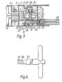
- the isolator comprises an input and output conductor 1 and 2 respectively, located within a housing comprising two insulating members 3, 4 secured together by nut and bolt arrangements 5.
- the two conductors are insulated one from the other within the housing and they may be bridged by a bridging contact shown generally as 6.
- the bridging contact comprises a pair of links 7 and 8 which are pivoted together on the output conductor 2 for movement about a pivot axis 9.
- the links are joined by a bolt 10 lying between the input and output conductors.
- the links have flat faces 11 and 12 respectively capable of engaging and making contact with flat faces 13 and 14 of the output conductor 2 and with corresponding flat faces on the inlet conductor 1.
- the bridging contact also includes an insulating housing section 15 which fits closely between the housing sections 3 and 4 and shields the whole of the links 7 and 8 and the ends of the input and output conductors against accidental contact from the front 16 of the housing.
- One end of the bolt 10 is provided with two spaced eyes 17 through which passes an eccentric section 18 of an operating shaft 19.
- the shaft is rotatably mounted within the housing relative to the links 7 and 8 and is axially captive relative to the links by virtue of an end plate 20 and annulus 21 engaging two opposite sides of a part 22 of the link 7. Between the end plate 20 and the annulus 21 the shaft is provided with a rib 23 engageable with the part 22 to limit rotation of the shaft through substantially 180° from the position shown in Figures 1 and 3.
- the opposite end of the bolt 10 carries a nut 24 and between that nut and the link 8 there are a sleeve 25 and a wavy spring washer 26.
- the plate 20 on the inner end of the shaft 19 is in the form of a circular disc with part cut from its circumference along a radius and a line at right angles thereto, so leaving a nose section.
- the nose section of the plate lies in a location adjacent to a raised portion 28 on the inner surface of the housing section 4. Movement of the shaft past the raised portion 28 is thus prevented.
- the cut away part of the plate 20 is brought into alignment with the raised portion 28 and the shaft is then free to move past the raised portion.
- Rotation of the shaft 19 between its two positions is effected by a hand-held operating member 30 formed of insulating material.
- the outer end of the shaft 19 is of square section and is fitted with an insulated tip 31 lying within an insulated sheath 32 projecting from the housing 15.
- the sheath is formed with a key way 34.
- the operating member has a metal core 33, the end of which is formed with a corresponding key 35, and is also formed with a square section opening 36 which may engage over the end 31 of the shaft 19. It will be seen that the operating member may only be moved into engagement with and disengagement from the shaft 19 when the key 35 is properly aligned with the key way 34.
- the isolator is shown with the bridging contacts in their closed position and in the condition where they are tightened into firm engagement with the input and output conductors.
- the cam arrangement formed by the eccentric section 18 of the shaft and the eyes 17 on the bolt 10 have cooperated to pull the bolt downwardly so applying a firm and constant pressure to the links to hold them against the conductors.
- the wavy spring washer 26 is flattened and exerts no spring effect. There is thus no element of this system that can relax with age and the contact pressure once applied will be maintained indefinitely at a constant level until it is released.
- the contact pressure In order to break the circuit the contact pressure must first be released so moving the bridging contact to its free condition and the bridging contact must then be moved to the open position as shown in broken lines in Figure 1. This operation is effected using the operating member 30.
- the angular orientation of the shaft 19 In the tightened condition of the bridging contact, as limited by the engagement of the rib 23, the angular orientation of the shaft 19 is such that with the key 35 and key way 34 aligned the operating member may be inserted into the sheath 32 with the opening 36 aligned for engagement with the end 31. Once they are engaged the operating member may be turned through substantially 180°. It will be seen that on such rotation the operating member becomes trapped within the sheath by virtue of the key 35 moving out of alignment with the key way 34.
Landscapes
- Conductive Materials (AREA)
- Control Of Motors That Do Not Use Commutators (AREA)
- Mechanisms For Operating Contacts (AREA)
- Driving Mechanisms And Operating Circuits Of Arc-Extinguishing High-Tension Switches (AREA)
- Switch Cases, Indication, And Locking (AREA)
Claims (12)
Priority Applications (1)
| Application Number | Priority Date | Filing Date | Title |
|---|---|---|---|
| AT84308799T ATE43748T1 (de) | 1983-12-24 | 1984-12-17 | Elektrische trennschalter. |
Applications Claiming Priority (2)
| Application Number | Priority Date | Filing Date | Title |
|---|---|---|---|
| GB8334481 | 1983-12-24 | ||
| GB838334481A GB8334481D0 (en) | 1983-12-24 | 1983-12-24 | Electrical isolators |
Publications (3)
| Publication Number | Publication Date |
|---|---|
| EP0147150A2 EP0147150A2 (de) | 1985-07-03 |
| EP0147150A3 EP0147150A3 (en) | 1986-08-13 |
| EP0147150B1 true EP0147150B1 (de) | 1989-05-31 |
Family
ID=10553853
Family Applications (1)
| Application Number | Title | Priority Date | Filing Date |
|---|---|---|---|
| EP84308799A Expired EP0147150B1 (de) | 1983-12-24 | 1984-12-17 | Elektrische Trennschalter |
Country Status (12)
| Country | Link |
|---|---|
| US (1) | US4633047A (de) |
| EP (1) | EP0147150B1 (de) |
| JP (1) | JPS60227322A (de) |
| AT (1) | ATE43748T1 (de) |
| AU (1) | AU569600B2 (de) |
| CA (1) | CA1256923A (de) |
| DE (1) | DE3478534D1 (de) |
| GB (2) | GB8334481D0 (de) |
| MY (1) | MY100889A (de) |
| NZ (1) | NZ210649A (de) |
| SG (1) | SG7588G (de) |
| ZA (1) | ZA849742B (de) |
Families Citing this family (6)
| Publication number | Priority date | Publication date | Assignee | Title |
|---|---|---|---|---|
| DE69427348T2 (de) | 1994-09-01 | 2002-06-13 | Solutia Europe N.V./S.A., Bruessel/Bruxelles | Hexamethylene Phosphonatkonzentrat |
| KR0167647B1 (ko) * | 1995-12-23 | 1999-01-15 | 김광호 | 테스크 탑 컴퓨터의 안전 잠금 장치 |
| US6362445B1 (en) * | 2000-01-03 | 2002-03-26 | Eaton Corporation | Modular, miniaturized switchgear |
| US6242708B1 (en) * | 2000-01-03 | 2001-06-05 | Eaton Corporation | Isolator switch |
| US6373015B1 (en) * | 2000-01-03 | 2002-04-16 | Eaton Corporation | Integral load connector module |
| CN113823515B (zh) * | 2021-09-27 | 2024-09-03 | 广东电网有限责任公司 | 一种通信接口屏保护通道开关操作工具 |
Family Cites Families (16)
| Publication number | Priority date | Publication date | Assignee | Title |
|---|---|---|---|---|
| US28243A (en) * | 1860-05-08 | williams | ||
| US1018501A (en) * | 1910-02-15 | 1912-02-27 | William H Jordan | Electric cut-out or switch. |
| US1540795A (en) * | 1918-07-15 | 1925-06-09 | Bryson D Horton | Cabinet for electric switches |
| GB363045A (en) * | 1930-10-18 | 1931-12-17 | Brookhirst Switchgear Ltd | Improvements in interlocking means between isolating switches, and the casings of switchgear and the like connected thereto |
| GB514697A (en) * | 1938-05-13 | 1939-11-15 | George Pasmore Cosway | Improvements in electric disconnecting links |
| DE714084C (de) * | 1940-04-03 | 1941-11-21 | Sachsenwerk Licht & Kraft Ag | Trennschalter |
| US2660648A (en) * | 1950-02-16 | 1953-11-24 | Maxwell E Sparrow | Electric switch |
| GB902739A (en) * | 1957-09-18 | 1962-08-09 | Adamson Green And Company Ltd | Improvements in and relating to electrical fuse-switches |
| DE1086778B (de) * | 1958-10-24 | 1960-08-11 | Neumann Hochspannungs App K G | Handbetaetigbares Trennmesser, insbesondere sichtbare Trennstrecke |
| US3183335A (en) * | 1962-03-23 | 1965-05-11 | Albert & J M Anderson Mfg Co | High pressure contact switch with rotatable locking means |
| US3244827A (en) * | 1962-12-13 | 1966-04-05 | Kelek Company | Switch actuating mechanism |
| GB1059545A (en) * | 1964-02-10 | 1967-02-22 | Adamson Green And Company Ltd | Improvements in and relating to electrical isolators |
| GB1183525A (en) * | 1967-02-20 | 1970-03-11 | British Insulated Callenders | Improvements in or relating to electric fusegear |
| US3519970A (en) * | 1967-10-31 | 1970-07-07 | G & W Electric Speciality Co | Current limiting fuse oil switch cut-out assembly |
| GB1227158A (de) * | 1968-11-15 | 1971-04-07 | ||
| USRE28243E (en) | 1973-02-26 | 1974-11-12 | Bolted contact switch with cam means for overcoming magnetic pinch forces on contact blades |
-
1983
- 1983-12-24 GB GB838334481A patent/GB8334481D0/en active Pending
-
1984
- 1984-12-14 ZA ZA849742A patent/ZA849742B/xx unknown
- 1984-12-17 AT AT84308799T patent/ATE43748T1/de not_active IP Right Cessation
- 1984-12-17 EP EP84308799A patent/EP0147150B1/de not_active Expired
- 1984-12-17 GB GB08431763A patent/GB2156587B/en not_active Expired
- 1984-12-17 DE DE8484308799T patent/DE3478534D1/de not_active Expired
- 1984-12-18 AU AU36882/84A patent/AU569600B2/en not_active Expired
- 1984-12-20 NZ NZ210649A patent/NZ210649A/en unknown
- 1984-12-20 US US06/684,014 patent/US4633047A/en not_active Expired - Lifetime
- 1984-12-21 CA CA000470922A patent/CA1256923A/en not_active Expired
- 1984-12-24 JP JP59271080A patent/JPS60227322A/ja active Granted
-
1987
- 1987-06-18 MY MYPI87000841A patent/MY100889A/en unknown
-
1988
- 1988-02-02 SG SG75/88A patent/SG7588G/en unknown
Also Published As
| Publication number | Publication date |
|---|---|
| ZA849742B (en) | 1985-07-31 |
| ATE43748T1 (de) | 1989-06-15 |
| GB2156587B (en) | 1987-11-18 |
| EP0147150A2 (de) | 1985-07-03 |
| DE3478534D1 (en) | 1989-07-06 |
| GB8334481D0 (en) | 1984-02-01 |
| JPH053713B2 (de) | 1993-01-18 |
| GB2156587A (en) | 1985-10-09 |
| AU3688284A (en) | 1985-07-04 |
| SG7588G (en) | 1988-07-01 |
| EP0147150A3 (en) | 1986-08-13 |
| US4633047A (en) | 1986-12-30 |
| CA1256923A (en) | 1989-07-04 |
| AU569600B2 (en) | 1988-02-11 |
| MY100889A (en) | 1991-05-16 |
| JPS60227322A (ja) | 1985-11-12 |
| NZ210649A (en) | 1987-11-27 |
| GB8431763D0 (en) | 1985-01-30 |
Similar Documents
| Publication | Publication Date | Title |
|---|---|---|
| KR100319407B1 (ko) | 배전용 개폐기기의 아크 소호장치 | |
| US4633047A (en) | Isolator switch with interlock | |
| US2272717A (en) | Circuit interrupting device | |
| US2370206A (en) | Circuit breaker | |
| US4555602A (en) | Draw out switchgear and operating mechanism | |
| US2621271A (en) | Switch construction | |
| KR20170000322U (ko) | 링메인유닛의 개폐기 인터록 장치 | |
| US2914627A (en) | Draw-out type switch-fuse assembly | |
| CA2215364C (en) | Circuit-interrupting device with handling features | |
| US3504142A (en) | High voltage electric switch | |
| US2354907A (en) | Electric switch | |
| US4095065A (en) | Safety trip mechanism for multi-position switch | |
| KR100505053B1 (ko) | 다회로 차단기의 토글형 접지 스위치 | |
| US2024744A (en) | Circuit breaker | |
| US2333459A (en) | Electric circuit breaker | |
| KR102485880B1 (ko) | 가스절연개폐장치의 단로기 및 접지스위치 조작기 | |
| US2835768A (en) | Load break interrupter | |
| CN1056705C (zh) | 带有安全装置的电气设备及断路器 | |
| KR101869720B1 (ko) | 가스절연차단기 | |
| US1976609A (en) | Electrical apparatus | |
| KR100631004B1 (ko) | 다회로 차단기의 접지장치 | |
| US2438121A (en) | Tool for applying fuse links to fused cutouts | |
| KR200301490Y1 (ko) | 가스절연 개폐장치의 단로기 안전장치 | |
| US3335237A (en) | By-pass switch | |
| CN203800401U (zh) | 旁路器、抽架及配电系统 |
Legal Events
| Date | Code | Title | Description |
|---|---|---|---|
| PUAI | Public reference made under article 153(3) epc to a published international application that has entered the european phase |
Free format text: ORIGINAL CODE: 0009012 |
|
| AK | Designated contracting states |
Designated state(s): AT BE CH DE FR GB IT LI LU NL SE |
|
| PUAL | Search report despatched |
Free format text: ORIGINAL CODE: 0009013 |
|
| AK | Designated contracting states |
Kind code of ref document: A3 Designated state(s): AT BE CH DE FR GB IT LI LU NL SE |
|
| 17P | Request for examination filed |
Effective date: 19860925 |
|
| 17Q | First examination report despatched |
Effective date: 19871211 |
|
| ITF | It: translation for a ep patent filed | ||
| RBV | Designated contracting states (corrected) |
Designated state(s): AT BE CH DE FR IT LI LU NL SE |
|
| GRAA | (expected) grant |
Free format text: ORIGINAL CODE: 0009210 |
|
| AK | Designated contracting states |
Kind code of ref document: B1 Designated state(s): AT BE CH DE FR IT LI LU NL SE |
|
| REF | Corresponds to: |
Ref document number: 43748 Country of ref document: AT Date of ref document: 19890615 Kind code of ref document: T |
|
| REF | Corresponds to: |
Ref document number: 3478534 Country of ref document: DE Date of ref document: 19890706 |
|
| ET | Fr: translation filed | ||
| PLBE | No opposition filed within time limit |
Free format text: ORIGINAL CODE: 0009261 |
|
| STAA | Information on the status of an ep patent application or granted ep patent |
Free format text: STATUS: NO OPPOSITION FILED WITHIN TIME LIMIT |
|
| 26N | No opposition filed | ||
| ITTA | It: last paid annual fee | ||
| REG | Reference to a national code |
Ref country code: CH Ref legal event code: PFA Free format text: MERLIN GERIN LIMITED |
|
| ITPR | It: changes in ownership of a european patent |
Owner name: CAMBIO RAGIONE SOCIALE;YORKSHIRE SWITCHGEAR LIMITE |
|
| REG | Reference to a national code |
Ref country code: FR Ref legal event code: CD |
|
| NLT1 | Nl: modifications of names registered in virtue of documents presented to the patent office pursuant to art. 16 a, paragraph 1 |
Owner name: YORKSHIRE SWITCHGEAR LIMITED TE LEEDS, GROOT-BRITT |
|
| NLT1 | Nl: modifications of names registered in virtue of documents presented to the patent office pursuant to art. 16 a, paragraph 1 |
Owner name: MERLIN GERIN LIMITED TE LEEDS, GROOT-BRITTANNIE. |
|
| EPTA | Lu: last paid annual fee | ||
| EAL | Se: european patent in force in sweden |
Ref document number: 84308799.0 |
|
| REG | Reference to a national code |
Ref country code: CH Ref legal event code: PFA Free format text: MERLIN GERIN LIMITED TRANSFER- SCHNEIDER LIMITED |
|
| NLT1 | Nl: modifications of names registered in virtue of documents presented to the patent office pursuant to art. 16 a, paragraph 1 |
Owner name: SCHNEIDER LIMITED |
|
| REG | Reference to a national code |
Ref country code: FR Ref legal event code: CD |
|
| PGFP | Annual fee paid to national office [announced via postgrant information from national office to epo] |
Ref country code: SE Payment date: 20031204 Year of fee payment: 20 |
|
| PGFP | Annual fee paid to national office [announced via postgrant information from national office to epo] |
Ref country code: NL Payment date: 20031205 Year of fee payment: 20 |
|
| PGFP | Annual fee paid to national office [announced via postgrant information from national office to epo] |
Ref country code: FR Payment date: 20031210 Year of fee payment: 20 |
|
| PGFP | Annual fee paid to national office [announced via postgrant information from national office to epo] |
Ref country code: AT Payment date: 20031211 Year of fee payment: 20 |
|
| PGFP | Annual fee paid to national office [announced via postgrant information from national office to epo] |
Ref country code: LU Payment date: 20031216 Year of fee payment: 20 |
|
| PGFP | Annual fee paid to national office [announced via postgrant information from national office to epo] |
Ref country code: CH Payment date: 20031223 Year of fee payment: 20 |
|
| PGFP | Annual fee paid to national office [announced via postgrant information from national office to epo] |
Ref country code: DE Payment date: 20031229 Year of fee payment: 20 |
|
| PGFP | Annual fee paid to national office [announced via postgrant information from national office to epo] |
Ref country code: BE Payment date: 20040212 Year of fee payment: 20 |
|
| PG25 | Lapsed in a contracting state [announced via postgrant information from national office to epo] |
Ref country code: LI Free format text: LAPSE BECAUSE OF EXPIRATION OF PROTECTION Effective date: 20041216 Ref country code: CH Free format text: LAPSE BECAUSE OF EXPIRATION OF PROTECTION Effective date: 20041216 |
|
| PG25 | Lapsed in a contracting state [announced via postgrant information from national office to epo] |
Ref country code: NL Free format text: LAPSE BECAUSE OF EXPIRATION OF PROTECTION Effective date: 20041217 Ref country code: LU Free format text: LAPSE BECAUSE OF EXPIRATION OF PROTECTION Effective date: 20041217 |
|
| BE20 | Be: patent expired |
Owner name: *SCHNEIDER LTD Effective date: 20041217 |
|
| REG | Reference to a national code |
Ref country code: CH Ref legal event code: PL |
|
| EUG | Se: european patent has lapsed | ||
| NLV7 | Nl: ceased due to reaching the maximum lifetime of a patent |
Effective date: 20041217 |
|
| EUG | Se: european patent has lapsed |