EP0147259A1 - Marqueur à diode-laser pour cinématographie ultra-rapide - Google Patents
Marqueur à diode-laser pour cinématographie ultra-rapide Download PDFInfo
- Publication number
- EP0147259A1 EP0147259A1 EP84402215A EP84402215A EP0147259A1 EP 0147259 A1 EP0147259 A1 EP 0147259A1 EP 84402215 A EP84402215 A EP 84402215A EP 84402215 A EP84402215 A EP 84402215A EP 0147259 A1 EP0147259 A1 EP 0147259A1
- Authority
- EP
- European Patent Office
- Prior art keywords
- diode
- laser
- camera
- pulse
- marker according
- Prior art date
- Legal status (The legal status is an assumption and is not a legal conclusion. Google has not performed a legal analysis and makes no representation as to the accuracy of the status listed.)
- Granted
Links
- 239000003550 marker Substances 0.000 title claims description 27
- 230000005540 biological transmission Effects 0.000 claims abstract description 10
- 230000003287 optical effect Effects 0.000 claims description 10
- 239000013307 optical fiber Substances 0.000 claims description 4
- 238000001228 spectrum Methods 0.000 claims description 3
- 230000002123 temporal effect Effects 0.000 abstract description 2
- 230000001276 controlling effect Effects 0.000 description 4
- 238000000034 method Methods 0.000 description 3
- 235000021183 entrée Nutrition 0.000 description 2
- 230000001360 synchronised effect Effects 0.000 description 2
- 238000004880 explosion Methods 0.000 description 1
- 125000005842 heteroatom Chemical group 0.000 description 1
- 230000005855 radiation Effects 0.000 description 1
- 230000001105 regulatory effect Effects 0.000 description 1
Images


Classifications
-
- H—ELECTRICITY
- H01—ELECTRIC ELEMENTS
- H01S—DEVICES USING THE PROCESS OF LIGHT AMPLIFICATION BY STIMULATED EMISSION OF RADIATION [LASER] TO AMPLIFY OR GENERATE LIGHT; DEVICES USING STIMULATED EMISSION OF ELECTROMAGNETIC RADIATION IN WAVE RANGES OTHER THAN OPTICAL
- H01S5/00—Semiconductor lasers
- H01S5/04—Processes or apparatus for excitation, e.g. pumping, e.g. by electron beams
- H01S5/042—Electrical excitation ; Circuits therefor
-
- G—PHYSICS
- G03—PHOTOGRAPHY; CINEMATOGRAPHY; ANALOGOUS TECHNIQUES USING WAVES OTHER THAN OPTICAL WAVES; ELECTROGRAPHY; HOLOGRAPHY
- G03B—APPARATUS OR ARRANGEMENTS FOR TAKING PHOTOGRAPHS OR FOR PROJECTING OR VIEWING THEM; APPARATUS OR ARRANGEMENTS EMPLOYING ANALOGOUS TECHNIQUES USING WAVES OTHER THAN OPTICAL WAVES; ACCESSORIES THEREFOR
- G03B17/00—Details of cameras or camera bodies; Accessories therefor
- G03B17/24—Details of cameras or camera bodies; Accessories therefor with means for separately producing marks on the film, e.g. title, time of exposure
- G03B17/245—Optical means
-
- G—PHYSICS
- G03—PHOTOGRAPHY; CINEMATOGRAPHY; ANALOGOUS TECHNIQUES USING WAVES OTHER THAN OPTICAL WAVES; ELECTROGRAPHY; HOLOGRAPHY
- G03B—APPARATUS OR ARRANGEMENTS FOR TAKING PHOTOGRAPHS OR FOR PROJECTING OR VIEWING THEM; APPARATUS OR ARRANGEMENTS EMPLOYING ANALOGOUS TECHNIQUES USING WAVES OTHER THAN OPTICAL WAVES; ACCESSORIES THEREFOR
- G03B39/00—High-speed photography
-
- G—PHYSICS
- G03—PHOTOGRAPHY; CINEMATOGRAPHY; ANALOGOUS TECHNIQUES USING WAVES OTHER THAN OPTICAL WAVES; ELECTROGRAPHY; HOLOGRAPHY
- G03B—APPARATUS OR ARRANGEMENTS FOR TAKING PHOTOGRAPHS OR FOR PROJECTING OR VIEWING THEM; APPARATUS OR ARRANGEMENTS EMPLOYING ANALOGOUS TECHNIQUES USING WAVES OTHER THAN OPTICAL WAVES; ACCESSORIES THEREFOR
- G03B2217/00—Details of cameras or camera bodies; Accessories therefor
- G03B2217/24—Details of cameras or camera bodies; Accessories therefor with means for separately producing marks on the film
- G03B2217/242—Details of the marking device
- G03B2217/243—Optical devices
Definitions
- the present invention relates to a laser diode marker for ultra-fast cinematography. It applies in particular to the temporal location of events.
- ultra-fast cinematography is a technique consisting in filming, using an appropriate camera, an event whose duration is very short and can be of the order of a few tens of microseconds, or even less.
- a device comprising a light-emitting diode whose radiation emitted is located in the near infrared, in association with an electronic tube camera equipped with a photocathode of type S 20 or S 20R.
- Such a marker has the disadvantage of leading to pale or even unusable recordings, given the low radiance of the light source used and the fact that the photocathode used is only slightly sensitive to the near infrared.
- the object of the present invention is to remedy this drawback.
- the marker object of the invention makes it possible to make recordings much more contrasted than those obtained with the known marker described above, because it uses a laser diode whose radiance is much higher than that of a light emitting diode and which is therefore much better suited to ultra-fast cinematography, a technique which requires significant light power given the speed of the events studied.
- Such a diode-laser is moreover significantly more powerful than light-emitting diodes and continuous diode-lasers which are only capable of delivering a light power of the order of a few milliwatts whereas a power-operated diode-laser of pulses can emit multiple watts. Admittedly, this emission takes place for a very short instant (approximately a few hundred nanoseconds) compared to light-emitting diodes and conventional laser diodes, the emission of which can be continuous, but this is not troublesome given the short duration of the events filmed by ultra-fast cinematography.
- the maximum duration of a light pulse that a power diode with pulse operation is capable of emitting remains compatible with the duration of the events studied by ultra-fast cinematography. Indeed, a classic use of a power diode with pulse operation, in fields other than ultra-fast cinematography, lies in the production of a light pulse, of the order of a few hundred nanoseconds with such a diode, then possibly other identical light pulses while waiting enough between the pulses not to damage the diode.
- the previous so-called “single-pulse” use is possible with events which last for example a few milliseconds, but, given the extreme rapidity of most of the events studied by ultra-fast cinematography, we use in the present invention, preferably and in an original manner, the power diode-laser "in multi-pulses", that is to say by associating the diode-laser with control means making it possible to obtain a plurality of pulses luminous whose sum of durations is at most equal to the single pulse conventionally obtained, so as not to deteriorate the diode.
- the power diode laser used is for example a power diode with a single hetero structure.
- the camera is for example an electronic camera which is provided with a slot to delimit the optical field of the camera and which has a photosensitive surface exposed to the field delimited by the slot.
- the diode-laser is placed in the field delimited by the slot, at the edge of this field, and the means of -transmission comprise a optical focusing of the light signal through the slit, on the photosensitive surface.
- the transmission means comprise an optical fiber, one end of which is optically coupled to the diode-laser and the other end of which is optically coupled to the photo-sensitive surface, at the edge of the field. delimited by The slot.
- the camera can also be a mechanical-optical camera provided with a slot for delimiting the optical field of the camera, the diode-laser then being chosen so as to emit light belonging to the visible region of the electromagnetic spectrum.
- the diode-laser With this other type of camera, comprising a rotating mirror capable of reflecting the image of the field delimited by the slit on a photosensitive support or film constituting in this case said photosensitive surface, the diode-laser can be placed in this field, at the edge of the latter, the transmission means then comprising an optical system for focusing the light signal on the photosensitive support by means of the rotating mirror.
- the electronic control means comprise means for producing a determined number of high intensity electrical pulses, the sum of the durations of which is at most equal to the maximum duration of a Light pulse that the diode-laser is capable of emitting.
- the power amplifier comprises power transistors of the HMOS or VMOS type, for amplifying the electrical pulses received at its input.
- This power amplifier can successively include an impedance adapter gain stage, an impedance step-down stage in a follower source and a current gain supply stage, the last two stages being produced using said power transistors.
- FIG. 1 there is shown schematically a recording 2 of an event, obtained using an ultra-fast cinematographic camera.
- event is meant the deformation or movement of an object, for example the movement of a bullet in the process of perforating a wall, or more generally any visible physical phenomenon such as lightning for example.
- the event consists for example of a brutal radial deformation of a cylinder observed by La tranche, using a slit camera aiming at a diameter of the cylinder, which leads to a recording 2 comprising a surface limited by two lines 3.
- the invention makes it possible to mark this recording with the aid of dots 4 regularly spaced and aligned opposite a line 3, preferably at the edge of the recording 2.
- the invention would also make it possible to mark an ultra-fast cinematographic recording of an event using one or more points corresponding to interesting moments of the event studied.
- the marker object of the invention is not limited to use with a slit camera but can be used with any ultra-fast cinematographic camera.
- FIG. 2 there is shown schematically a particular embodiment of the object marker of the invention, used with an electronic slit camera 5 intended to film an event such as the deformation of an object 6.
- the camera 5 comprises known manner a slit 7 which delimits the field of the camera, a photosensitive surface constituted by a photocathode 8 which is exposed to the field delimited by the slit 7 and a luminescent screen 9 opposite which is placed a film 10 to obtain a recording of L event studied.
- Camera 5 also includes a lens 11 which is situated in front of the slot 7 and which makes it possible to form the image of the object 6 on the photocathode 8, through the slot 7.
- the object 6 is represented near the objective 11, because of the limited size of FIG. 2.
- object 6 is much further from objective 11. This is why the light rays 12 coming from object 6 are represented by straight lines paralteles.
- the camera 5 is for example a camera sold by the company THOMSON under the reference TSN and provided with a photocathode of type S 20 or S 20R.
- the marker according to the invention comprises a power diode laser operating in pulses 13, electronic means 14 for controlling this diode and means 15 for transmitting to the photocathode 8, light signals which the diode-laser is capable of. issue.
- these transmission means 15 comprise an optical fiber 16, one end of which 17 is optically coupled to the diode-laser 13 and the other end of which 18 is optically coupled to the cathode 8, at the edge of the field delimited by the slot 7.
- the other end 18 of the optical fiber 16 is for example fixed opposite the photocathode 8, at one end of the slot 8.
- the diode-Laser 13 consists, for example, of a diode-laser with a single heterojunction marketed by the company RCA under the reference SG 2002A whose peak power is of the order of 9 W at 904 nm for a maximum duration of 200 ns.
- FIG. 3 schematically shows another particular embodiment of the marker object of the invention, comprising the diode-laser 13 associated with the electronic control means 14 and still cooperating with the electronic camera at slot 5.
- the diode-laser 13 is placed in the field delimited by the slot 7, at the edge of this field and the transmission means 15 are constituted by an optic 19 such as a converging lens , called "image transport lens” and arranged on the optical axis Z of the objective 11 of the camera, between this objective 11 and the slot 7, so that the light rays 12 coming from the object 6 are focused at a point F by the objective 11 then sent to the photocathode 8 via the image transport lens 19.
- an optic 19 such as a converging lens , called "image transport lens” and arranged on the optical axis Z of the objective 11 of the camera, between this objective 11 and the slot 7, so that the light rays 12 coming from the object 6 are focused at a point F by the objective 11 then sent to the photocathode 8 via the image transport lens
- the diode-laser 13 is placed between the latter and the objective 11, the emissive face of the diode-laser 13 being located in a plane passing through the point F and perpendicular to the axis Z, so that a light signal emitted by the diode-laser is focused on an edge of the photocathode 8 via of the image transport lens 19.
- FIG 4 there is shown schematically another particular embodiment of the marker object of the invention, comprising the laser diode 13 associated with the electronic control means 14 and cooperating with an ultra-fast cinematographic camera of the mechanical-optical type , comprising a slit 20 to delimit the optical field of the camera, a lens 21 located in front of the slit 20 and a rotating mirror 22 capable of reflecting the image of the field delimited by the slit on a photo-sensitive support or film 23.
- the transmission means 15 comprise a focusing optic 24 such as a converging LENS, located on the optical axis X of the objective 21, between the slot 20 and the rotating mirror 22.
- the respective provisions of the objective 21 and LENS 24 are such that the light rays 12 from phenomenon studied, for example of the object 6 being deformed, are focused at a point F 1 of the slit 20 and then sent from this point F 1 on the film 23 via the lens 24 then the rotating mirror 22.
- the diode-laser 13 is chosen so as to emit light belonging to the visible region of the electromagnetic spectrum.
- the diode-Laser 13 is on the other hand placed in the optical field delimited by the slot 20, on the edge thereof. To do this, the diode-laser 13 is fixed to an edge of the slot 20 so that the light signals which it is capable of emitting are focused on an edge of the film 23 by means of the lens 24 and the rotating mirror 22.
- FIG. 5 there is shown schematically a particular embodiment of the electronic control means 14, in the case where one uses a power laser diode with pulse operation. It includes means 25 for synchronizing the operation of the diode-laser 13 with the start of the event studied and with the operation of the camera 5, as well as means 26 for producing a determined number of strong electrical pulses. intensity, the sum of the durations of which is at most equal to the maximum duration of a light pulse that the diode-laser is capable of emitting.
- These production means 26 include a pulse counter 27, an electric pulse generator 28 and a power amplifier 29.
- the counter 27 includes reset means which are connected to the synchronization means 25.
- the output of the counter 27 is connected to the input of the electric pulse generator 28, the output of which is connected to the input of the power amplifier 29.
- the output of the latter is connected to the diode-laser 13.
- the output of the electric pulse generator 28 is connected to an input of the counter 27, so that the latter is controlled by the electric pulse generator 28.
- the synchronization means 25 can be conceived as a kind of switch which controls both the operation of the diode-laser, the operation of the camera and means 30 allowing the event to be started to begin.
- these means 30 can consist of a detonator whose Explosion causes this deformation.
- the operation of the electronic control means 14 is as follows:
- the synchronization means 25 trigger The counter 27 which in turn triggers The generator 28.
- the generator 28 thus delivers electrical pulses whose intensity is amplified by the power amplifier 29 so as to obtain pulses whose intensity is high, for example of the order of 10 amperes, in order to be able to supply the power diode-laser.
- the electrical pulses emitted by the generator 28 are counted by the counter 27.
- the counter 27 commands The generator 28 to stop (via a Logic gate forming part of the generator , The counter output being connected to this Logic gate).
- the generator 28 includes means for adjusting the time separating two electrical pulses that it is capable of emitting and for adjusting the duration of these pulses.
- the determined number of pulses is such that the sum of the durations thereof is at most equal to The maximum duration of a light pulse that the diode-laser is capable of emitting.
- the counter 27 is set to count up to this determined number.
- the diode-laser sold by the company RCA under the reference SG 2002A is capable of emitting pulses of 200 ns.
- the electronic control means 14 make it possible, so to speak, to subdivide such a pulse of 200 ns into N pulses of 200 / N ns.
- the number N being for example equal to 20, the generator 28 can be adjusted so as to separate each of the 20 pulses of the following one by a determined time interval, equal to 1 ⁇ s for example, so as to obtain a regular marking for a event which lasts approximately 20 ps.
- FIG 6 there is shown schematically a particular embodiment of the power amplifier 29. This latter is produced using two power transistors 31 and 32 of the HMOS type.
- the input E of the power amp is connected to the output of the electric pulse generator 28 by a coaxial cable 33.
- the power amplifier 29 is supplied by a source 34 of direct current whose negative pole N is grounded.
- the power amplifier 29 firstly comprises an impedance adapter gain stage produced using an NPN transistor 35.
- the base of this transistor is connected to Input E. It is also connected to Ground via an electrical resistance R 4 .
- the collector of said transistor is connected to one end A of an electrical resistance R 1 , the other end B of this resistance R 1 being connected to the positive pole P of the source 34.
- the emitter of transistor 35 is connected to Ground through an electrical resistance R 2 .
- the power amplifier 29 then comprises a stage operating in step-down impedance as a follower source, produced using the power transistor 31. This is connected by its door to the end A of the resistor R 1 and by its drain to the ground.
- the source of the power transistor 31 is connected, by means of an electrical resistance R 3 , to the positive pole P of the source 34.
- the power amplifier 29 finally comprises a stage for supplying the current gain, produced using the other power transistor 32, the gate of which is connected to the link between the source of the power transistor 31 and the electrical resistance. R 3 .
- this other power transistor 32 is connected by its drain, to the anode of the diode-laser 13, and by its source, to the positive pole P of the current source 34.
- the cathode of the diode-laser 13 is connected to ground.
- a freewheeling diode 36 is mounted head to tail with the diode-laser 13, between the terminals of the latter.
- the electrical resistances R 1 , R 2 , R 3 and R 4 have respectively the values 56 ohms, 5 ohms, 5 ohms, and 57 ohms,
- the voltage across the terminals of the source 34 is 15 V
- the transistor 35 is of the type which is marketed by The Company RTC under the reference 2N2219 A
- the power laser diode is of the type which is marketed by The Company RCA under The reference SG 2002A
- the wheel diode free is of the kind that is marketed by La cios RTC under the reference 1N4148
- the two power transistors 31 and 32 are of the kind that is marketed by La cios INTERNATIONAL RECTIFIER under the reference IRF 9520.
- DMOS type transistors could be used to make the power amplifier 29.
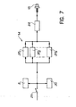
- FIG 7 there is shown schematically another particular embodiment of the control means 14 which can be used in the case where one simply wishes to mark one or more precise instants of the event using The pulse-powered power-13 diode-laser.
- this other embodiment comprises one or more adjustable monostable generators 37 1 , 37 2 , ..., 37 N whose number N is equal to the number d 'precise moments to mark and which are capable of generating each a single electrical impulse.
- the input of each monostable generator is connected to the synchronization means 25 and the output of each of these monostable generators is connected to the input E of the power amplifier 29, the output of which is connected to the diode-laser 13.
- Each monostable generator is regulated on the one hand so as to produce, at a determined time after the start of the event, an electrical pulse of appropriate duration and on the other hand, so that the sum of the durations of the pulses corresponding to the different generators monostable is at most equal to The maximum duration of a Light pulse that the diode-Laser is capable of emitting.
Landscapes
- Physics & Mathematics (AREA)
- General Physics & Mathematics (AREA)
- Condensed Matter Physics & Semiconductors (AREA)
- Electromagnetism (AREA)
- Optics & Photonics (AREA)
- Semiconductor Lasers (AREA)
- Studio Devices (AREA)
Abstract
Description
- La présente invention concerne un marqueur à diode-laser pour cinématographie ultra-rapide. Elle s'applique notamment au repérage temporel d'évène- ments.
- On sait que La cinématographie ultra-rapide est une technique consistant à filmer, à l'aide d'une caméra appropriée, un événement dont la durée est très courte et peut être de l'ordre de quelques dizaines de microsecondes, voire moins.
- Pour étudier un tel événement, après l'enregistrement de celui-ci sur un support photosensible ou film dont on a muni la caméra, on est amené à repérer un ou plusieurs instants particuliers, synchrones à l'événement, par exemple des instants séparés les uns des autres par un même intervalle de temps, en marquant Le support photosensible au moyen de signaux tu- mineux synchrones à ces instants particuliers.
- Pour ce faire, on peut utiliser un dispositif appelé "marqueur", comprenant une diode électroluminescente dont le rayonnement émis se situe dans le proche infrarouge, en association avec une caméra électronique à tube équipé d'une photocathode de type S 20 ou S 20R.
- Un tel marqueur présente L'inconvénient de conduire à des enregistrements pâles, voire inutilisables, compte tenu de La faible radiance de La source lumineuse utilisée et du fait que la photocathode employée n'est que peu sensible au proche infrarouge.
- La présente invention a pour but de remédier à cet inconvénient.
- Elle a pour objet un marqueur pour caméra cinématographique ultra-rapide, caractérisé en ce qu'il comprend :
- - au moins une diode-laser de puissance à fonctionnement par impulsions,
- - des moyens électroniques de commande de chaque diode-taser, permettant à celle-ci d'émettre un signal lumineux, et
- - des moyens de transmission de ce signal lumineux à une surface photosensible dont est munie La caméra.
- Le marqueur objet de l'invention permet de réaliser des enregistrements bien plus contrastés que ceux qui sont obtenus avec le marqueur connu décrit précédemment, du fait qu'il utilise une diode-laser dont la radiance est très supérieure à celte d'une diode électroluminescente et qui est donc bien mieux adaptée à La cinématographie ultra-rapide, technique qui nécessite une puissance Lumineuse importante étant donné La rapidité des événements étudiés.
- Une telle diode-laser est en outre nettement plus puissante que Les diodes électroluminescentes et Les diodes-lasers continues qui sont seulement capables de délivrer une puissance Lumineuse de L'ordre de quelques milliwatts alors qu'une diode-laser de puissance à fonctionnement par impulsions peut émettre plusieurs watts. Certes, cette émission a Lieu pendant un très court instant (environ quelques centaines de nanosecondes) comparativement aux diodes électroluminescentes et aux diodes-lasers classiques dont L'émission peut être continue, mais ceci n'est pas gênant compte tenu de La faible durée des événements filmés par cinématographie ultra-rapide.
- La durée maximale d'une impulsion Lumineuse qu'une diode-laser de puissance à fonctionnement par impulsions est capable d'émettre reste compatible avec La durée des événements étudiés par cinématographie ultra-rapide. En effet, une utilisation classique d'une diode-laser de puissance à fonctionnement par impulsions, dans des domaines autres que La cinématographie ultra-rapide, réside dans La production d'une impulsion lumineuse, de l'ordre de quelques centaines de nanosecondes avec une telle diode, puis éventuellement d'autres impulsions lumineuses identiques en attendant suffisamment entre les impulsions pour ne pas détériorer La diode. Dans la présente invention, l'utilisation précédente dite "en mono-impulsion" est possible avec des événements qui durent par exemple quelques millisecondes mais, compte tenu de l'extrême rapidité de La plupart des événements étudiés par cinématographie ultra-rapide, on utilise dans La présente invention, préférablement et de façon originale, la diode-laser de puissance "en multi-impulsions" c'est-à-dire en associant la diode-laser à des moyens de commande permettant d'obtenir une pluralité d'impulsions lumineuses dont La somme des durées est au plus égale à L'impuLsion unique classiquement obtenue, de façon à ne pas détériorer La diode. Tout se passe comme si on subdivisait une impulsion lumineuse unique en une pluralité d'impulsions lumineuses successives convenablement espacées. On peut ainsi "couvrir" La totalité d'un phénomène étudié dont La durée est par exemple de L'ordre de 10 microsecondes. En outre, on dispose ainsi d'un marqueur non seulement intense mais encore très précis.
- La diode-Laser de puissance utilisée est par exemple une diode-laser de puissance à simple hétéro- structure.
- La caméra est par exemple une caméra électronique qui est munie d'une fente pour délimiter Le champ optique de La caméra et qui comporte une surface photosensible exposée au champ délimité par La fente.
- Dans ce cas, selon une réalisation particulière de l'invention, La diode-laser est placée dans le champ délimité par La fente, en bordure de ce champ, et Les moyens de -transmission comportent une optique de focalisation du signal lumineux à travers La fente, sur La surface photosensible.
- Dans ce cas également, selon une autre réaLisation particulière, Les moyens de transmission comportent une fibre optique dont une extrémité est optiquement couplée à La diode-laser et dont L'autre extrémité est optiquement couplée à La surface photo- sensible, en bordure du champ délimité par La fente.
- On peut par exemple utiliser une caméra électronique à fente, sensible dans l'ultraviolet, La diode-laser étant alors une diode-laser émettant dans L'uLtravioLet.
- La caméra peut égatement être une caméra mécano-optique munie d'une fente pour délimiter le champ optique de La caméra, La diode-laser étant alors choisie de façon à émettre de La lumière appartenant à La région visible du spectre électro-magnétique.
- Avec cet autre type de caméra, comportant un miroir tournant apte à réfléchir L'image du champ déLimité par la fente sur un support photosensible ou film constituant dans ce cas Ladite surface photosensible, La diode-laser peut être placée dans ce champ, en bordure de celui-ci, les moyens de transmission comportant alors une optique de focalisation du signal Lumineux sur Le support photosensible par l'intermédiaire du miroir tournant.
- SeLon un mode de réalisation particulier de L'invention, Les moyens électroniques de commande comprennent des moyens de production d'un nombre déterminé d'impulsions électriques de forte intensité, dont La somme des durées est au plus égale à La durée maximale d'une impulsion Lumineuse que La diode-laser est capable d'émettre.
- Dans ce cas, La caméra étant destinée à filmer un événement, les moyens électroniques de commande peuvent comprendre :
- - des moyens de synchronisation du fonctionnement de La diode-Laser avec Le début de l'événement,
- - un générateur d'impulsions électriques,
- - un compteur d'impulsions commandé par Les moyens de synchronisation, asservi par Le générateur d'impulsions et commandant celui-ci, de manière que Le générateur d'impulsions produise un nombre déterminé d'impulsions dont La somme des durées soit au plus égale à La durée maximale d'une impulsions lumineuse que la diode-laser est capable d'émettre, puis s'arrête une fois ce nombre produit, et
- - un amplificateur de puissance, pour amplifier les impulsions issues du générateur d'impulsions, les impulsions amplifiées étant alors transmises à la diode-laser.
- SeLon un autre mode de réalisation particulier, La caméra étant destinée à filmer un événement, les moyens électroniques de commande peuvent comprendre :
- - des moyens de synchronisation du fonctionnement de La diode-laser avec le début de L'événement,
- - au moins un générateur d'impulsion électrique monostable réglable, chaque générateur monostable ayant son entrée reliée aux moyens de synchronisation et étant réglé de manière à émettre à un moment déterminé, après le début de L'événement, une impulsion électrique de durée appropriée et de manière que La somme des durées des impulsions émises par les générateurs monostables soit au plus égale à La durée maximale d'une impulsion Lumineuse que La diode-laser est capable d'émettre, et
- - un amplificateur de puissance dont l'entrée est reliée à la sortie de chaque générateur monostable et dont la sortie est reliéé à la diode-laser.
- Enfin, dans un mode de réalisation préféré, l'amplificateur de puissance comprend des transistors de puissance du type HMOS ou VMOS, pour amplifier Les impulsions électriques reçues à son entrée.
- Cet amplificateur de puissance peùt comprendre successivement un étage de gain adaptateur d'impédance, un étage abaisseur d'impédance en source suiveuse et un étage fournisseur de gain en courant, Les deux derniers étages étant réalisés à L'aide desdits transistors de puissance.
- L'invention sera mieux comprise à la lecture de La description qui suit, d'exemples de réalisation donnés à titre indicatif et nullement limitatif, en référence aux figures annexées sur LesqueLLes :
- - La figure 1 est une vue schématique d'un enregistrement cinématographique ultra-rapide d'un événement, comportant des marquages effectués par L'invention,
- - les figures 2 et 3 sont des vues schématiques de modes de réalisation particuliers du marqueur objet de l'invention, dans Le cas où celui-ci est utiLisé avec une caméra électronique à fente,
- - La figure 4 est une vue schématique d'un autre mode de réalisation particulier du marqueur objet de l'invention, dans Le cas où celui-ci est utiLisé avec une caméra mécano-optique,
- - La figure 5 est une vue schématique d'un mode de réalisation particulier des moyens électroniques de commande d'un marqueur selon l'invention,
- - La figure 6 est une vue schématique d'un mode de réalisation particulier d'un amplificateur de puissance dont sont munis ces moyens électroniques de commande, et
- - la figure 7 est une vue schématique d'un autre mode de réalisation particulier des moyens électroniques de commande.
- Sur La figure 1, on a représenté schématiquement un enregistrement 2 d'un événement, obtenu à l'aide d'une caméra cinématographique ultra-rapide. Par "événement", on entend La déformation ou Le mouvement d'un objet, par exemple Le mouvement d'une balle en train de perforer une paroi, ou plus généralement tout phénomène physique visible tel que La foudre par exemple. Sur La figure 1, l'événement consiste par exemple en une brutale déformation radiale d'un cylindre observé par La tranche, à l'aide d'une caméra à fente visant un diamètre du cylindre, ce qui conduit à un enregistrement 2 comportant une surface limitée par deux lignes 3. L'invention permet de marquer cet enregistrement à l'aide de points 4 régulièrement espacés et alignés en regard d'une ligne 3, de préférence en bordure de L'enregistrement 2. L'invention permettrait également de marquer un enregistrement cinématographique ultra-rapide d'un événement à L'aide d'un ou plusieurs points correspondant à des moments intéressants de L'événement étudié. Bien entendu, le marqueur objet de L'invention n'est pas limité à un emploi avec une caméra à fente mais peut être utilisé avec toute caméra cinématographique ultra-rapide.
- Sur La figure 2, on a représenté schématiquement un mode de réalisation particulier du marqueur objet de l'invention, utilisé avec une caméra électronique à fente 5 destinée à filmer un événement teL que La déformation d'un objet 6. La caméra 5 comporte de façon connue une fente 7 qui délimite le champ de La caméra, une surface photosensible constituée par une photocathode 8 qui est exposée au champ délimité par La fente 7 et un écran luminescent 9 en regard duquel est disposé un film 10 pour obtenir un enregistrement de L'événement étudié. La caméra 5 comporte également un objectif 11 qui est situé devant La fente 7 et qui permet de former l'image de L'objet 6 sur La photocathode 8, à travers La fente 7. Sur La figure 2, l'objet 6 est représenté à proximité de L'objectif 11, à cause de La taille limitée de La figure 2. En pratique, L'objet 6 est beaucoup plus éloigné de l'objectif 11. C'est pourquoi les rayons lumineux 12 issus de L'objet 6 sont représentés par des droites paraltèles.
- La caméra 5 est par exemple une caméra commercialisée par La société THOMSON sous La référence TSN et munie d'une photocathode de type S 20 ou S 20R.
- Le marqueur selon L'invention comporte une diode-laser de puissance à fonctionnement par impulsions 13, des moyens électroniques 14 pour commander cette diode et des moyens 15 de transmission à La photocathode 8, des signaux Lumineux que La diode-Laser est capable d'émettre. Dans le mode de réalisation particulier représenté sur La figure 2, ces moyens 15 de transmission comprennent une fibre optique 16 dont une extrémité 17 est optiquement couplée à La diode-laser 13 et dont L'autre extrémité 18 est optiquement couplée à La cathode 8, en bordure du champ délimité par La fente 7. L'autre extrémité 18 de La fibre optique 16 est par exemple fixée en regard de La photocathode 8, à une extrémité de La fente 8.
- La diode-Laser 13 consiste par exemple en une diode-laser à simple hétérojonction commercialisée par La société RCA sous La référence SG 2002A dont La puissance crête est de L'ordre de 9 W à 904 nm pendant une durée maximale de 200 ns.
- Sur La figure 3, on a représenté schématiquement un autre mode de réalisation particulier du marqueur objet de l'invention, comprenant La diode-laser 13 associée aux moyens électroniques de commande 14 et coopérant encore avec La caméra électronique à fente 5. Dans cet autre mode de réalisation particulier, La diode-laser 13 est placée dans Le champ délimité par la fente 7, en bordure de ce champ et les moyens de transmission 15 sont constitués par une optique 19 telle qu'une lentille convergente, appelée "lentille de transport d'image" et disposée sur l'axe optique Z de L'objectif 11 de La caméra, entre cet objectif 11 et La fente 7, de manière que les rayons lumineux 12 issus de l'objet 6 soient focalisés en un point F par L'objectif 11 puis envoyés sur la photocathode 8 par l'intermédiaire de La lentille de transport d'image 19. La diode-laser 13 est disposée entre cette dernière et l'ojectif 11, la face émissive de la diode-laser 13 étant située dans un plan passant par Le point F et perpendiculaire à l'axe Z, de telle façon qu'un signal Lumineux émis par La diode-laser soit focalisé sur un bord de La photocathode 8 par l'intermédiaire de La LentiLLe de transport d'image 19.
- Sur La figure 4, on a représenté schématiquement un autre mode de réalisation particulier du marqueur objet de l'invention, comprenant la diode-laser 13 associée aux moyens électroniques de commande 14 et coopérant avec une caméra cinématographique ultra-rapide de type mécano-optique, comportant une fente 20 pour délimiter Le champ optique de La caméra, un objectif 21 situé devant La fente 20 et un miroir tournant 22 apte à réfléchir L'image du champ délimité par La fente sur un support photo-sensible ou film 23.
- Les moyens de transmission 15 comportent une optique de focalisation 24 telle qu'une LentiLLe convergente, située sur l'axe optique X de L'objectif 21, entre La fente 20 et Le miroir tournant 22. Les dispositions respectives de L'objectif 21 et de La LentiLLe 24 sont telles que les rayons Lumineux 12 issus du phénomène étudié, par exemple de L'objet 6 en train de se déformer, soient focalisés en un point F1 de La fente 20 puis envoyés à partir de ce point F1 sur le film 23 par L'intermédiaire de La lentille 24 puis du miroir tournant 22.
- Dans le mode de réalisation particulier représenté sur La figure 4, la diode-laser 13 est choisie de façon à émettre de La lumière appartenant à La région visible du spectre électromagnétique. La diode-Laser 13 est d'autre part placée dans le champ optique délimité par La fente 20, en bordure de celui-ci. Pour ce faire, La diode-laser 13 est fixée sur un bord de La fente 20 de façon que Les signaux lumineux qu'elle est susceptible d'émettre soient focalisés sur un bord du film 23 par L'intermédiaire de La LentiLLe 24 et du miroir tournant 22.
- Sur La figure 5, on a représenté schématiquement un mode de réalisation particulier des moyens électroniques de commande 14, dans Le cas où L'on utiLise une diode-laser de puissance à fonctionnement par impulsions. IL comprend des moyens 25 de synchronisation du fonctionnement de La diode-laser 13 avec le début de l'événement étudié et avec Le fonctionnement de La caméra 5, ainsi que des moyens 26 de production d'un nombre déterminé d'impulsions électriques de forte intensité, dont La somme des durées est au plus égale à La durée maximale d'une impulsion Lumineuse que La diode-laser est capable d'émettre.
- Ces moyens 26 de production comprennent un compteur d'impulsions 27, un générateur d'impulsions électriques 28 et un amplificateur de puissance 29.
- Le compteur 27 comporte des moyens de remise à zéro qui sont reliés aux moyens de synchronisation 25. La sortie du compteur 27 est reliée à L'entrée du générateur d'impulsion électrique 28 dont La sortie est reliée à l'entrée de l'amplificateur de puissance 29. La sortie de celui-ci est reliée à La diode-laser 13. En outre, la sortie du générateur d'impuLsions électriques 28 est reliée à une entrée du compteur 27, de sorte que celui-ci est asservi par Le générateur d'impuLsions électriques 28.
- Les moyens de synchronisation 25 peuvent se concevoir comme une sorte d'interrupteur qui commande à La fois Le fonctionnement de La diode-laser, le fonctionnement de La caméra et des moyens 30 permettant de faire débuter L'événement à étudier. Par exemple, dans le cas de La déformation d'un objet, ces moyens 30 peuvent consister en un détonateur dont L'expLosion provoque cette déformation.
- Le fonctionnement des moyens électroniques de commande 14 est Le suivant : Les moyens de synchronisation 25 déclenchent Le compteur 27 qui déclenche à son tour Le générateur 28. Le générateur 28 délivre ainsi des impulsions électriques dont l'intensité est amplifiée par l'amplificateur de puissance 29 de manière à obtenir des impulsions dont L'intensité est élevée, par exemple de l'ordre de 10 ampères, pour pouvoir alimenter la diode-laser de puissance. Les impulsions électriques émises par le générateur 28 sont comptabilisées par le compteur 27. Lorsqu'un nombre déterminé d'impulsions est obtenu, Le compteur 27 commande L'arrêt du générateur 28 (par L'intermédiaire d'une porte Logique faisant partie du générateur, La sortie du compteur étant reliée à cette porte Logique). Le générateur 28 comporte des moyens pour régler Le temps séparant deux impulsions électriques qu'il est susceptible d'émettre et pour régler La durée de ces impulsions.
- Le nombre déterminé d'impulsions est tel que La somme des durées de celles-ci soit au plus égale à La durée maximale d'une impulsion lumineuse que La diode-laser est capable d'émettre. Le compteur 27 est réglé pour compter jusqu'à ce nombre déterminé.
- Par exemple, La diode-laser commercialisée par La société RCA sous La référence SG 2002A est capable d'émettre des impulsions de 200 ns. Les moyens électroniques de commande 14 permettent pour ainsi dire de subdiviser une telle impulsion de 200 ns en N impulsions de 200/N ns. Le nombre N étant par exemple égal à 20, on peut régler le générateur 28 de façon à séparer chacune des 20 impulsions de La suivante par un intervalle de temps déterminé, égal à 1 µs par exemple, de manière à obtenir un marquage régulier pour un événement qui dure environ 20 ps.
- Sur La figure 6, on a représenté schématiquement un mode de réalisation particulier de L'ampLificateur de puissance 29. CeLui-ci est réalisé à l'aide de deux transistors de puissance 31 et 32 du type HMOS. L'entrée E de L'ampLificateur de puissance est reliée à La sortie du générateur d'impulsions électriques 28 par un câble coaxial 33. En outre, l'amplificateur de puissance 29 est alimenté par une source 34 de courant continu dont le pôle négatif N est mis à La masse.
- L'amplificateur de puissance 29 comprend d'abord un étage de gain adaptateur d'impédance réalisé à l'aide d'un transistor 35 de type NPN. La base de ce transistor est reliée à L'entrée E. Elle est également reliée à La masse par L'intermédiaire d'une résistance électrique R4. Le collecteur dudit transistor est relié à une extrémité A d'une résistance électrique R1, L'autre extrémité B de cette résistance R1 étant reliée au pôle positif P de La source 34. Enfin, l'émetteur du transistor 35 est relié à La masse par L'intermédiaire d'une résistance électrique R2.
- L'amplificateur de puissance 29 comprend ensuite un étage fonctionnant en abaisseur d'impédance en source suiveuse, réalisé à L'aide du transistor de puissance 31. CeLui-ci est relié par sa porte à l'extrémité A de La résistance R1 et par son drain à La masse. La source du transistor de puissance 31 est reliée, par l'intermédiaire d'une résistance électrique R3, au pôle positif P de La source 34.
- L'amplificateur de puissance 29 comprend enfin un étage pour fournir Le gain en courant, réalisé à l'aide de l'autre transistor de puissance 32 dont La porte est reliée à La liaison entre La source du transistor de puissance 31 et La résistance électrique R3. En outre, cet autre transistor de puissance 32 est relié par son drain, à l'anode de la diode-laser 13, et par sa source, au pôle positif P de La source de courant 34.
- La cathode de La diode-laser 13 est reliée à La masse. Pour éviter les surtensions aux bornes de cette diode-laser, une diode de roue Libre 36 est montée tête-bêche avec La diode-laser 13, entre les bornes de cette dernière.
- A titre indicatif et nullement limitatif, Les résistances électriques R1, R2, R3 et R4 ont respectivement pour valeurs 56 ohms, 5 ohms, 5 ohms, et 57 ohms, La tension aux bornes de La source 34 est de 15 V, Le transistor 35 est du genre de celui qui est commercialisé par La Société RTC sous La référence 2N2219 A, La diode-laser de puissance est du genre de celle qui est commercialisée par La Société RCA sous La référence SG 2002A, La diode de roue libre est du genre de celle qui est commercialisée par La Société RTC sous La référence 1N4148 et Les deux transistors de puissance 31 et 32 sont du genre de celui qui est commercialié par La Société INTERNATIONAL RECTIFIER sous La référence IRF 9520. Au Lieu de transistors HMOS, on pourrait utiliser des transistors du type DMOS pour réaliser l'amplificateur de puissance 29.
- Sur La figure 7, on a représenté schématiquement un autre mode de réalisation particulier des moyens de commande 14 que L'on peut utiliser dans Le cas où l'on souhaite simplement marquer un ou plusieurs instants précis de L'événement à l'aide de La diode-laser de puissance-13 à fonctionnement par impulsions. Outre Les moyens 25 de synchronisation et l'amplificateur de puissance 29 mentionnés plus haut, cet autre mode de réalisation comprend un ou plusieurs générateurs monostables réglables 371, 372,...,37N dont le nombre N est égal au nombre d'instants précis à marquer et qui sont aptes à engendrer chacun une unique impulsion électrique. L'entrée de chaque générateur monostable est reliée aux moyens 25 de synchronisation et La sortie de chacun de ces générateurs monostables est reliée à L'entrée E de l'amplificateur de puissance 29 dont La sortie est reliée à La diode-Laser 13. Chaque générateur monostable est réglé d'une part de façon à produire, à un moment déterminé après Le début de l'événement, une impulsion électrique de durée appropriée et d'autre part, de façon que La somme des durées des impulsions correspondant aux différents générateurs monostables soit au plus égale à La durée maximale d'une impulsion Lumineuse que La diode-Laser est capable d'émettre.
- Par exemple, pour un événement qui dure 20 ps, on peut souhaiter marquer trois instants se produisant respectivement 1 µs, 5 µs et 10 ps après Le début de l'événement. On utilise alors trois générateurs monostabtes que L'on règle pour produire chacun une impulsion de 20 ns, respectivement 1 µs, 5 µs et 10 µs après Le début de L'événement.
Claims (11)
Applications Claiming Priority (2)
| Application Number | Priority Date | Filing Date | Title |
|---|---|---|---|
| FR8317812 | 1983-11-09 | ||
| FR8317812A FR2554607B1 (fr) | 1983-11-09 | 1983-11-09 | Marqueur a diode-laser pour cinematographie ultra-rapide |
Publications (2)
| Publication Number | Publication Date |
|---|---|
| EP0147259A1 true EP0147259A1 (fr) | 1985-07-03 |
| EP0147259B1 EP0147259B1 (fr) | 1989-02-01 |
Family
ID=9293935
Family Applications (1)
| Application Number | Title | Priority Date | Filing Date |
|---|---|---|---|
| EP84402215A Expired EP0147259B1 (fr) | 1983-11-09 | 1984-11-05 | Marqueur à diode-laser pour cinématographie ultra-rapide |
Country Status (4)
| Country | Link |
|---|---|
| US (1) | US4602858A (fr) |
| EP (1) | EP0147259B1 (fr) |
| DE (1) | DE3476587D1 (fr) |
| FR (1) | FR2554607B1 (fr) |
Families Citing this family (7)
| Publication number | Priority date | Publication date | Assignee | Title |
|---|---|---|---|---|
| RU2224276C2 (ru) * | 2001-09-24 | 2004-02-20 | Российский Федеральный Ядерный Центр - Всероссийский Научно-Исследовательский Институт Экспериментальной Физики | Лазерный способ оптической градуировки развертки скоростного фоторегистратора |
| US7952602B2 (en) * | 2008-09-02 | 2011-05-31 | Coherent, Inc. | Wide field diode-laser marker with swinging projection-optics |
| US7961370B2 (en) * | 2008-09-29 | 2011-06-14 | Coherent, Inc. | Two frequency resonantly excited MEMS mirror for diode-laser marker |
| US7952603B2 (en) * | 2008-09-29 | 2011-05-31 | Coherent, Inc. | Diode-laser marker with one-axis scanning mirror mounted on a translatable carriage |
| US20100078857A1 (en) * | 2008-09-29 | 2010-04-01 | Coherent, Inc. | Diode-laser marker with one-axis scanning mirror mounted on a translatable carriage |
| US8558859B2 (en) | 2011-04-20 | 2013-10-15 | Coherent, Inc. | Laser printer with multiple laser-beam sources |
| RU2727088C1 (ru) * | 2019-02-19 | 2020-07-17 | Федеральное Государственное Унитарное Предприятие "Всероссийский Научно-Исследовательский Институт Автоматики Им.Н.Л.Духова" (Фгуп "Внииа") | Способ ввода в скоростной фотохронографический регистратор оптического излучения для нанесения меток времени |
Citations (4)
| Publication number | Priority date | Publication date | Assignee | Title |
|---|---|---|---|---|
| US3603974A (en) * | 1969-12-31 | 1971-09-07 | Nasa | High speed photo-optical time recording |
| US3858063A (en) * | 1973-04-02 | 1974-12-31 | Redlake Corp | Timed light pulse generator |
| DE2820908A1 (de) * | 1977-05-16 | 1978-11-23 | Joseph Skovajsa | Vorrichtung zur oertlichen behandlung eines patienten insbesondere fuer akupunktur oder aurikulartherapie |
| US4400812A (en) * | 1981-06-15 | 1983-08-23 | Santa Barbara Research Center | Laser drive circuits |
Family Cites Families (2)
| Publication number | Priority date | Publication date | Assignee | Title |
|---|---|---|---|---|
| US3044068A (en) * | 1959-04-27 | 1962-07-10 | Avco Corp | Means for and method of recording time markers |
| US3449046A (en) * | 1967-01-04 | 1969-06-10 | Optomechanisms Inc | Film code annotating means |
-
1983
- 1983-11-09 FR FR8317812A patent/FR2554607B1/fr not_active Expired
-
1984
- 1984-11-01 US US06/667,354 patent/US4602858A/en not_active Expired - Fee Related
- 1984-11-05 EP EP84402215A patent/EP0147259B1/fr not_active Expired
- 1984-11-05 DE DE8484402215T patent/DE3476587D1/de not_active Expired
Patent Citations (4)
| Publication number | Priority date | Publication date | Assignee | Title |
|---|---|---|---|---|
| US3603974A (en) * | 1969-12-31 | 1971-09-07 | Nasa | High speed photo-optical time recording |
| US3858063A (en) * | 1973-04-02 | 1974-12-31 | Redlake Corp | Timed light pulse generator |
| DE2820908A1 (de) * | 1977-05-16 | 1978-11-23 | Joseph Skovajsa | Vorrichtung zur oertlichen behandlung eines patienten insbesondere fuer akupunktur oder aurikulartherapie |
| US4400812A (en) * | 1981-06-15 | 1983-08-23 | Santa Barbara Research Center | Laser drive circuits |
Non-Patent Citations (2)
| Title |
|---|
| FEINWERKTECHNIK & MESSTECHNIK, vol. 89, no. 5, juillet/août 1981, pages 225-228, Munich, DE; M. FABIAN: "Pulsschaltungen für Laserdioden" * |
| PROCEEDINGS OF THE NINTH INTERNATIONAL CONGRESS ON HIGH SPEED PHOTOGRAPHY, Denver, Colorado, 2-7 août 1970, pages 68-74, SMPTE, New York, US; F. CHABANNES et al.: "Application of phase-locked solid lasers to high-speed cinematography" * |
Also Published As
| Publication number | Publication date |
|---|---|
| US4602858A (en) | 1986-07-29 |
| DE3476587D1 (en) | 1989-03-09 |
| EP0147259B1 (fr) | 1989-02-01 |
| FR2554607B1 (fr) | 1986-10-10 |
| FR2554607A1 (fr) | 1985-05-10 |
Similar Documents
| Publication | Publication Date | Title |
|---|---|---|
| CN107690050B (zh) | 用于提供白天场景和夜间场景的改进的图像的系统 | |
| EP0147259B1 (fr) | Marqueur à diode-laser pour cinématographie ultra-rapide | |
| EP0206912A1 (fr) | Système pour la localisation d'un mobile | |
| JPH02211782A (ja) | 不可視光を使用する結像ライダー | |
| EP0567385A1 (fr) | Dispositif d'acquisition d'images d'un objet | |
| EP1304907A1 (fr) | Dispositif d'éclairage ou de signalisation à diodes électroluminescentes | |
| FR2607346A1 (fr) | Agencement de groupes d'elements de circuit de traitement de signaux | |
| EP0833122B1 (fr) | Autodirecteur d'un corps volant | |
| EP0425355A1 (fr) | Système pour la localisation d'un mobile | |
| EP0127870A1 (fr) | Dispositif pour détecter une caméra infrarouge adverse | |
| EP0100387B1 (fr) | Perfectionnements aux dispositifs optiques de détection de proximité | |
| EP1628111B1 (fr) | Procédé et dispositif pour la réalisation d'une liaison optique par éclats lumineux | |
| EP0034091B1 (fr) | Dispositif anti-éblouissement pour caméra de télévision, applicable notamment au guidage de missile | |
| FR2574549A1 (fr) | Dispositif d'ombre portee en rayons x | |
| FR2504684A1 (fr) | Perfectionnements aux dispositifs optiques de detection de proximite | |
| EP1429479A1 (fr) | Procédé et dispositif pour la réalisation d'une liaison optique par impulsions laser. | |
| EP0228735B1 (fr) | Dispositif d'insolation pour la génération de masques | |
| FR2458823A1 (fr) | Detecteur de proximite | |
| CN109087839A (zh) | 用于测试和标定场发射电子源阵列的场发射显微镜系统 | |
| FR2797081A1 (fr) | Procede d'identification d'un vehicule automobile immatricule et appareil d'identification de vehicule automobile correspondant | |
| EP1943530B1 (fr) | Dispositif d'analyse d'un circuit integre | |
| CH648930A5 (en) | Method and device for measuring the deviation in the position of a surface | |
| JP5139891B2 (ja) | 撮像システムおよび周辺モニタ装置 | |
| CH386710A (fr) | Procédé pour relever, par voies cinématographiques multiples,la trajectoire d'un mobile, notamment d'un engin aérien, et installation pour la mise en oeuvre de ce procédé | |
| EP0056556A1 (fr) | Tube analyseur à cible à accumulation |
Legal Events
| Date | Code | Title | Description |
|---|---|---|---|
| PUAI | Public reference made under article 153(3) epc to a published international application that has entered the european phase |
Free format text: ORIGINAL CODE: 0009012 |
|
| AK | Designated contracting states |
Designated state(s): DE GB NL |
|
| 17P | Request for examination filed |
Effective date: 19851204 |
|
| 17Q | First examination report despatched |
Effective date: 19870205 |
|
| RAP1 | Party data changed (applicant data changed or rights of an application transferred) |
Owner name: COMMISSARIAT A L'ENERGIE ATOMIQUE |
|
| GRAA | (expected) grant |
Free format text: ORIGINAL CODE: 0009210 |
|
| AK | Designated contracting states |
Kind code of ref document: B1 Designated state(s): DE GB NL |
|
| REF | Corresponds to: |
Ref document number: 3476587 Country of ref document: DE Date of ref document: 19890309 |
|
| GBT | Gb: translation of ep patent filed (gb section 77(6)(a)/1977) | ||
| PLBE | No opposition filed within time limit |
Free format text: ORIGINAL CODE: 0009261 |
|
| STAA | Information on the status of an ep patent application or granted ep patent |
Free format text: STATUS: NO OPPOSITION FILED WITHIN TIME LIMIT |
|
| 26N | No opposition filed | ||
| PGFP | Annual fee paid to national office [announced via postgrant information from national office to epo] |
Ref country code: DE Payment date: 19901015 Year of fee payment: 7 |
|
| PGFP | Annual fee paid to national office [announced via postgrant information from national office to epo] |
Ref country code: GB Payment date: 19901105 Year of fee payment: 7 |
|
| PGFP | Annual fee paid to national office [announced via postgrant information from national office to epo] |
Ref country code: NL Payment date: 19901130 Year of fee payment: 7 |
|
| PG25 | Lapsed in a contracting state [announced via postgrant information from national office to epo] |
Ref country code: GB Effective date: 19911105 |
|
| PG25 | Lapsed in a contracting state [announced via postgrant information from national office to epo] |
Ref country code: NL Effective date: 19920601 |
|
| GBPC | Gb: european patent ceased through non-payment of renewal fee | ||
| NLV4 | Nl: lapsed or anulled due to non-payment of the annual fee | ||
| PG25 | Lapsed in a contracting state [announced via postgrant information from national office to epo] |
Ref country code: DE Effective date: 19920801 |