EP0147281B1 - Vorrichtung zum Regeln eines Fluiddurchflussstromes mit veränderlichem Speisedruck - Google Patents
Vorrichtung zum Regeln eines Fluiddurchflussstromes mit veränderlichem Speisedruck Download PDFInfo
- Publication number
- EP0147281B1 EP0147281B1 EP84402525A EP84402525A EP0147281B1 EP 0147281 B1 EP0147281 B1 EP 0147281B1 EP 84402525 A EP84402525 A EP 84402525A EP 84402525 A EP84402525 A EP 84402525A EP 0147281 B1 EP0147281 B1 EP 0147281B1
- Authority
- EP
- European Patent Office
- Prior art keywords
- pipe
- tube
- outlet
- flow
- cylindrical chamber
- Prior art date
- Legal status (The legal status is an assumption and is not a legal conclusion. Google has not performed a legal analysis and makes no representation as to the accuracy of the status listed.)
- Expired
Links
- 239000012530 fluid Substances 0.000 title claims description 28
- DGAQECJNVWCQMB-PUAWFVPOSA-M Ilexoside XXIX Chemical compound C[C@@H]1CC[C@@]2(CC[C@@]3(C(=CC[C@H]4[C@]3(CC[C@@H]5[C@@]4(CC[C@@H](C5(C)C)OS(=O)(=O)[O-])C)C)[C@@H]2[C@]1(C)O)C)C(=O)O[C@H]6[C@@H]([C@H]([C@@H]([C@H](O6)CO)O)O)O.[Na+] DGAQECJNVWCQMB-PUAWFVPOSA-M 0.000 claims description 23
- 229910052708 sodium Inorganic materials 0.000 claims description 23
- 239000011734 sodium Substances 0.000 claims description 23
- 230000001105 regulatory effect Effects 0.000 claims description 13
- 230000002093 peripheral effect Effects 0.000 claims description 11
- 238000001816 cooling Methods 0.000 claims description 10
- 239000007788 liquid Substances 0.000 claims description 10
- 239000000446 fuel Substances 0.000 claims description 7
- 230000000149 penetrating effect Effects 0.000 claims 1
- 230000000712 assembly Effects 0.000 description 21
- 238000000429 assembly Methods 0.000 description 21
- 230000033228 biological regulation Effects 0.000 description 6
- 230000002950 deficient Effects 0.000 description 4
- 238000005086 pumping Methods 0.000 description 4
- 230000004907 flux Effects 0.000 description 3
- 230000003993 interaction Effects 0.000 description 3
- 239000002826 coolant Substances 0.000 description 2
- 230000007423 decrease Effects 0.000 description 2
- 238000010586 diagram Methods 0.000 description 2
- 230000000694 effects Effects 0.000 description 2
- 239000000463 material Substances 0.000 description 2
- 238000000034 method Methods 0.000 description 2
- 238000012958 reprocessing Methods 0.000 description 2
- 238000003466 welding Methods 0.000 description 2
- 229910000831 Steel Inorganic materials 0.000 description 1
- 230000002745 absorbent Effects 0.000 description 1
- 239000002250 absorbent Substances 0.000 description 1
- 230000009471 action Effects 0.000 description 1
- 230000009849 deactivation Effects 0.000 description 1
- PCHJSUWPFVWCPO-UHFFFAOYSA-N gold Chemical compound [Au] PCHJSUWPFVWCPO-UHFFFAOYSA-N 0.000 description 1
- 239000010931 gold Substances 0.000 description 1
- 229910052737 gold Inorganic materials 0.000 description 1
- 238000009434 installation Methods 0.000 description 1
- 230000008569 process Effects 0.000 description 1
- 230000001902 propagating effect Effects 0.000 description 1
- 230000005855 radiation Effects 0.000 description 1
- 230000001869 rapid Effects 0.000 description 1
- 230000007420 reactivation Effects 0.000 description 1
- 239000002915 spent fuel radioactive waste Substances 0.000 description 1
- 239000010959 steel Substances 0.000 description 1
Images


Classifications
-
- G—PHYSICS
- G21—NUCLEAR PHYSICS; NUCLEAR ENGINEERING
- G21C—NUCLEAR REACTORS
- G21C15/00—Cooling arrangements within the pressure vessel containing the core; Selection of specific coolants
- G21C15/02—Arrangements or disposition of passages in which heat is transferred to the coolant; Coolant flow control devices
-
- F—MECHANICAL ENGINEERING; LIGHTING; HEATING; WEAPONS; BLASTING
- F15—FLUID-PRESSURE ACTUATORS; HYDRAULICS OR PNEUMATICS IN GENERAL
- F15C—FLUID-CIRCUIT ELEMENTS PREDOMINANTLY USED FOR COMPUTING OR CONTROL PURPOSES
- F15C1/00—Circuit elements having no moving parts
- F15C1/16—Vortex devices, i.e. devices in which use is made of the pressure drop associated with vortex motion in a fluid
-
- G—PHYSICS
- G05—CONTROLLING; REGULATING
- G05D—SYSTEMS FOR CONTROLLING OR REGULATING NON-ELECTRIC VARIABLES
- G05D7/00—Control of flow
- G05D7/01—Control of flow without auxiliary power
-
- Y—GENERAL TAGGING OF NEW TECHNOLOGICAL DEVELOPMENTS; GENERAL TAGGING OF CROSS-SECTIONAL TECHNOLOGIES SPANNING OVER SEVERAL SECTIONS OF THE IPC; TECHNICAL SUBJECTS COVERED BY FORMER USPC CROSS-REFERENCE ART COLLECTIONS [XRACs] AND DIGESTS
- Y02—TECHNOLOGIES OR APPLICATIONS FOR MITIGATION OR ADAPTATION AGAINST CLIMATE CHANGE
- Y02E—REDUCTION OF GREENHOUSE GAS [GHG] EMISSIONS, RELATED TO ENERGY GENERATION, TRANSMISSION OR DISTRIBUTION
- Y02E30/00—Energy generation of nuclear origin
- Y02E30/30—Nuclear fission reactors
Definitions
- the invention relates to a device for regulating the flow rate of a fluid stream whose supply pressure is variable.
- the used assemblies taken from the core are arranged vertically on the core support, like the active assemblies of the reactor, according to a peripheral ring located outside a covering area serving as a radiation shield and itself arranged around of the active part of the heart.
- This covering layer is formed by assemblies containing steel or a more absorbent material which strongly limit the neutron flux coming from the core, so that the used assemblies are not reactivated significantly, in their storage area.
- Used assemblies however produce a certain amount of heat which depends in particular on the intensity of the reactivation, and therefore on the residual neutron flux in the peripheral storage area.
- the active assemblies are each cooled by a stream of liquid sodium entering the assembly through its lower part and passing through it along its entire length.
- the cooling flow rate of the active fuel assemblies depends on their position in the reactor core, and when the assembly's own pressure drop is not sufficient to impose the desired sodium flow rate, a flow control system formed is used. by a succession of diaphragms placed in the lower part of the assembly. But for a used assembly, the pressure drop of such a regulating system would in all cases be largely insufficient, given the low power released by the used assemblies in their internal storage locations and therefore the low flow rate necessary for their cooling. This is why a device is used which creates an additional pressure drop in the candle (or support tube) of the assembly constituted by a succession of diaphragms. But if this system does indeed provide the minimum cooling flow rate necessary for the most severe incidental operation of the reactor, at nominal speed, the assembly is still traversed by a flow rate much higher than the flow rate corresponding to the desirable heat removal.
- the flow control regulators known at present are of a complicated structure and have moving parts which are liable to function defective in the atmosphere of the reactor, in liquid sodium at high temperature.
- There are also known methods and devices for regulating flow which do not require the use of moving parts. Such devices can operate by separating the initial flow of regulated fluid into a main current and a substantially coaxial control current, propagating in the same direction, the main current surrounding the control current in which a pressure drop is created. The control current is then directed to the main current on which it acts so as to regulate the flow of fluid by direct interaction.
- the fluid stream is separated into a peripheral main stream and into a central control stream thanks to a tube arranged coaxially with the conduit in which the fluid circulates and constituting a chamber cylindrical pierced with openings opening into the peripheral space of the duct.
- the duct is made in the form of a convergent-divergent and the openings open at the neck of this convergent-divergent.
- FR-A-1 481 970 the main current is deflected at the input of a vortex by a control current on which a linear type pressure drop has been created.
- the object of the invention is therefore to propose a device for regulating the flow rate of a fluid stream inside a duct having an inlet end and an outlet end, comprising a tube fixed coaxially to the inside the duct and opening into a cylindrical chamber arranged in the duct coaxially with respect to this duct and providing outlet channels for directing the fluid entering the cylindrical chamber at the outlet of the tube in the form of a control current which is brought into contact with the main stream of fluid flowing in the conduit at the periphery of the tube, towards a peripheral space communicating with the outlet of the conduit and located between the external lateral surface of the cylindrical chamber and the internal lateral surface of the conduit, device which allows a very important limitation of the flow and a very good regulation of this flow whatever the variations of the pressure and which requires only simple means of setting in use, easily accommodated in a conduit of limited diameter.
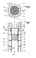
- conduit 1 arranged with its vertical axis in a fluid flow directed vertically and from bottom to top according to arrow 2.
- the conduit 1 channels a stream of fluid which enters the conduit 1 through its lower end inlet 1 a, the fluid stream being evacuated at the outlet of the device by the outlet end 1 b of smaller diameter than the inlet end 1 a.
- the plates 2a, 2b and 2c have series of substantially aligned openings such as 3a, 3b, 3c and 4a, 4b, 4c.
- Such pierced plates arranged transversely to a flow create a quadratic pressure drop in this flow, that is to say a pressure drop proportional to the square of the pressure or flow rate of this flow.
- the plates 2 are also pierced at their central part by circular openings whose centers are aligned on the vertical axis ZZ 'of the duct 1. These large-diameter circular openings allow the passage and fixing of a tube 6 arranged coaxially with the conduit 1.
- Structure 7 separating the interior space of the tube 6 into longitudinal channels 8 of small transverse dimension.
- Structure 7 may consist of a cylinder pierced with channels of axial direction and of small diameter.
- Such a structure 7 with longitudinal channels of small transverse dimension creates a linear pressure drop for a flow in circulation in the tube 6 in the direction of the axis ZZ '.
- Such a pressure drop is proportional to the flow rate of the fluid current passing through the tube 6.
- the tube 6 opens at its upper part into a cylindrical envelope 9 closed at its periphery by a ring 10 crossed by horizontal holes 12 and inclined relative to the radial direction (such as Gold for example) at a constant angle.
- the channels 12 open onto the lateral surface of the ring 10, in the upper peripheral zone 14 of the duct 1.
- the initial stream of fluid entering via the end 1a of the conduit 1 along arrow 2 ′ separates into two streams of the same direction and coaxial, one of these streams passing through the tube 6 and the other stream through the annular zone between the internal surface of the duct 1 and the external surface of the tube 6.
- the current 2'a passing in the peripheral annular zone surrounding the tube 6 is called the main current.
- the currents 2'a and 2'b move in the same direction, the current 2'a undergoing a quadratic type pressure drop during the crossing of the plates 2a, 2b, 2c and the current 2'b, a linear type pressure drop during the crossing of the structure 7.
- the stream 2'b enters the interior space of the cylindrical casing 9, the upper transverse wall of which deflects the stream 2'b towards the periphery of the casing 9 through which the inclined bores 12 pass.
- the current 2'b leaving through the holes 12 generates a vortex with an axis ZZ 'which rotates the main current 2'a which has passed through the pierced plates 2, in the upper peripheral annular space 14 of the conduit 1.
- the current 2'b in the form of a vortex meeting the main current 2'a acts on it and limits the total flow passing through the narrowing 1b by increasing the overall pressure drop of the device.
- control current 2'b in the form of a vortex The action of the control current 2'b in the form of a vortex, on the current 2'a by direct contact between these two currents depends on the pressure and the flow rate of the control current and therefore on the initial pressure and flow rate of the fluid at the entrance to conduit 1.
- FIG. 3 a diagram is shown showing on the ordinate the pressure drop undergone by a current of fluid during its passage through a regulating device and the flow rate in the regulating device on the abscissa.
- Curve A represents the linear type pressure drop characteristic of the control current 2'b in the channels 8 of the structure 7 inside the tube 6.
- Curve B represents the quadratic type pressure drop characteristic of the main current 2'a in its passage through the pierced plates 2.
- curve C represents the pressure drop characteristic of the entire regulating device shown in FIGS. 1 and 2.
- the pressure and the pumping rate are themselves increasing with the power required from the reactor.
- the flow rate is therefore well limited in this case to a value low enough not to reduce the reactor efficiency at nominal speed, while ensuring the necessary cooling for internal storage in incident mode.
- FIG. 4 the core support structure 15 of a fast neutron nuclear reactor is seen in which are assembled assembly support tubes such as 16.
- the lower part 17 of the assembly also called the base of the assembly is engaged in the support tube 16 in which it comes to rest.
- the assembly foot 17 has openings 18 for the passage of the coolant sodium in the assembly.
- the support tube 16 has openings 19 at their lower part for the passage of the liquid sodium which is injected into the structure 15 also called decking by the outlet pipes of the primary pumps plunging into the liquid sodium filling the tank.
- a regulator and flow limiter device according to the invention has been placed in the support tube 16 of the assembly, between the openings 19 and the lower part of the base 17 of the assembly.
- This flow control device comprises four perforated plates 21 of circular shape fixed by welding to the inner surface of the support tube 16. These plates 21 have circular central openings in which is engaged and fixed a tube 25 enclosing a structure 27 creating a loss linear charge in the stream of liquid sodium traversing the internal volume of the tube 25 separated into a large number of channels of small longitudinal section limited by the structure 26.
- the tube 25 opens into a cylindrical envelope 28 similar to the envelope 9 shown in FIG. 1 closed by a ring pierced with inclined channels.
- the stream of liquid sodium entering through the openings 19 and the pressure of which is variable as a function of the power level of the reactor is separated inside the support tube 16, into a main stream passing through the annular space between the inner surface of the tube 16 and the outer surface of the tube 25 and a central current passing through the tube 25 then into the cylindrical envelope 28, from which this current emerges in the form of a vortex through the openings provided at the periphery of the envelope 28
- This vortex serves as a control current for the main sodium current which has undergone pressure losses during the crossing of the drilled plates 21.
- the total current then passes through the narrowing 29.
- the tube 16 which is a used assembly arranged at the periphery of the core where it receives only a weak neutron flux slightly increasing, when the power demanded from the reactor increases.
- the main advantages of the flow control device according to the invention are to allow very effective limitation of the flow for pressure differences relative to the nominal operating regime of the fast neutron nuclear reactor and to ensure the minimum flow for the small pressure differences corresponding to the most severe incident operating case.
- the regulating device is very simple and can be easily housed in a cylindrical conduit such as a support tube for a fuel assembly of a fast neutron nuclear reactor. Such a device does not have any moving part and no part capable of destroying itself or of functioning in a defective manner, when it is immersed in the sodium coolant filling the tank of a fast neutron nuclear reactor.
- the pressure drop devices inserted on the main current and on the control current can be of a different type from those which have been described.
- this device can be constituted by any structure comprising for example a set of tubes arranged in parallel bundles or a stack of grids constituting longitudinal channels of small section.
- the quadratic pressure drop device placed at the periphery of the regulator and receiving the main stream of fluid can be produced in a different way from what has been described, either by an assembly of any number of plates with aligned or non-aligned openings or by a single plate having openings calibrated in any number.
- the device necessary for producing the vortex and for directing the control current towards the periphery part of the device can have a shape different from that which has been described, for example comprising spiral channels interposed between two parallel plates.
- the device according to the invention apply in all cases where it is desired to regulate a fluid current so as to obtain, for a small pressure variation between the inlet and the outlet of the device, a relatively large flow rate, and for a large variation in pressure, a low and slightly increasing flow.
Landscapes
- Engineering & Computer Science (AREA)
- Physics & Mathematics (AREA)
- General Engineering & Computer Science (AREA)
- General Physics & Mathematics (AREA)
- Automation & Control Theory (AREA)
- Plasma & Fusion (AREA)
- High Energy & Nuclear Physics (AREA)
- Theoretical Computer Science (AREA)
- Fluid Mechanics (AREA)
- Mechanical Engineering (AREA)
- Monitoring And Testing Of Nuclear Reactors (AREA)
Claims (2)
Applications Claiming Priority (2)
| Application Number | Priority Date | Filing Date | Title |
|---|---|---|---|
| FR8319733A FR2556482B1 (fr) | 1983-12-09 | 1983-12-09 | Procede et dispositif de regulation du debit d'un courant de fluide dont la pression d'alimentation est variable |
| FR8319733 | 1983-12-09 |
Publications (3)
| Publication Number | Publication Date |
|---|---|
| EP0147281A2 EP0147281A2 (de) | 1985-07-03 |
| EP0147281A3 EP0147281A3 (en) | 1985-07-31 |
| EP0147281B1 true EP0147281B1 (de) | 1988-06-01 |
Family
ID=9295017
Family Applications (1)
| Application Number | Title | Priority Date | Filing Date |
|---|---|---|---|
| EP84402525A Expired EP0147281B1 (de) | 1983-12-09 | 1984-12-06 | Vorrichtung zum Regeln eines Fluiddurchflussstromes mit veränderlichem Speisedruck |
Country Status (3)
| Country | Link |
|---|---|
| EP (1) | EP0147281B1 (de) |
| DE (1) | DE3471774D1 (de) |
| FR (1) | FR2556482B1 (de) |
Families Citing this family (3)
| Publication number | Priority date | Publication date | Assignee | Title |
|---|---|---|---|---|
| DE59502286D1 (de) * | 1994-12-21 | 1998-06-25 | Siemens Ag | Vorrichtung zur begrenzung des volumenstroms eines unter druck stehenden fluides |
| EP0995910A1 (de) * | 1998-10-20 | 2000-04-26 | Abb Research Ltd. | Wirbelventil |
| CN114859986A (zh) * | 2022-04-20 | 2022-08-05 | 中国核电工程有限公司 | 一种流量控制器及乏燃料后处理系统 |
Family Cites Families (5)
| Publication number | Priority date | Publication date | Assignee | Title |
|---|---|---|---|---|
| FR1463771A (fr) * | 1963-12-07 | 1966-07-22 | Snecma | Dispositif de réglage du débit de fluide dans un canal |
| US3424182A (en) * | 1965-05-25 | 1969-01-28 | Bendix Corp | Vortex valve |
| FR1481970A (fr) * | 1966-01-14 | 1967-05-26 | Bertin & Cie | Procédé de régulation d'un débit de fluide et dispositif de mise en oeuvre de ce precédé |
| US4164961A (en) * | 1977-07-28 | 1979-08-21 | The United States Of America As Represented By The Secretary Of The Army | Fluidic pressure/flow regulator |
| GB2017385B (en) * | 1978-03-07 | 1982-05-06 | Nuclear Power Co Ltd | Liquid metal cooled fast breeder nuclear reactors |
-
1983
- 1983-12-09 FR FR8319733A patent/FR2556482B1/fr not_active Expired
-
1984
- 1984-12-06 EP EP84402525A patent/EP0147281B1/de not_active Expired
- 1984-12-06 DE DE8484402525T patent/DE3471774D1/de not_active Expired
Also Published As
| Publication number | Publication date |
|---|---|
| EP0147281A3 (en) | 1985-07-31 |
| FR2556482A1 (fr) | 1985-06-14 |
| DE3471774D1 (en) | 1988-07-07 |
| EP0147281A2 (de) | 1985-07-03 |
| FR2556482B1 (fr) | 1986-11-21 |
Similar Documents
| Publication | Publication Date | Title |
|---|---|---|
| EP0059661B1 (de) | Vorrichtung zur Regelung der Durchflussmenge eines Fluids | |
| FR2697104A1 (fr) | Réacteur rapide équipé d'un système de commande pour réflecteur. | |
| EP0238390B1 (de) | Innere Struktur eines Kernreaktors mit länglichem Druckbehälter | |
| FR2700058A1 (fr) | Elément constituant interne d'un réacteur de fusion. | |
| EP0246969B1 (de) | Kleiner Druckwasserkernreaktor mit Naturumlauf | |
| EP0060777B1 (de) | Leichtwasserkernreaktor, dessen Kern durch Stäbe und Abstandsplatten eingeschlossen ist | |
| FR2715760A1 (fr) | Assemblage de combustible incluant des ailettes déflectrices pour dévier une composante d'un courant de fluide s'y écoulant. | |
| EP0163564B1 (de) | Schneller Neutronenkernreaktor mit Dampferzeuger, integriert im Behälter | |
| EP0147281A2 (de) | Vorrichtung zum Regeln eines Fluiddurchflussstromes mit veränderlichem Speisedruck | |
| EP0083545B1 (de) | Sicherheitsvorrichtung zur Ableitung der entstehenden Wärme beim Abschalten eines schnellen Brüters | |
| EP0258131B1 (de) | Notkühleinrichtung für schnellen Neutronenreaktor | |
| EP0607071B1 (de) | Wärmetauscher mit oben durch einen Überlauf gespeistes Sekundärfluid | |
| FR2652190A1 (fr) | Perfectionnements apportes aux reacteurs nucleaires. | |
| FR2481505A1 (fr) | Systeme d'arret automatique de reacteurs nucleaires | |
| EP0241345A1 (de) | Kernreaktor mit Strömungsführung in den oberen inneren Einbauten | |
| FR2555794A1 (fr) | Reacteur nucleaire a neutrons rapides equipe de moyens de refroidissement de secours | |
| EP0325879B1 (de) | Schneller Neutronenkernreaktor mit Zwischenwärmetauscher | |
| FR2489581A1 (fr) | Reacteur nucleaire a circulation du fluide primaire de refroidissement par convection mixte | |
| FR2533354A1 (fr) | Circuit caloporteur secondaire pour un reacteur nucleaire a metal liquide | |
| EP0216667B1 (de) | Rückhaltevorrichtung für eine Flüssigkeit um zu verhindern, dass eine offene, im wesentlichen horizontale Leitung beim Unterschreiten einer bestimmten Zuflussmenge leer läuft | |
| FR2987487A1 (fr) | Systeme d'evacuation de la puissance residuelle d'un reacteur nucleaire a neutrons rapides, utilisant une convection forcee dans l'espace intercuve | |
| FR2496320A1 (fr) | Reacteur nucleaire a eau sous pression et derive spectrale, comprenant des barres de commande mobiles et des elements de deplacement de l'eau d'absorption des neutrons lents par rapport au coeur du reacteur; et procede pour regler la puissance du reacteur | |
| EP4639582A1 (de) | Modular aufgebauter druckwasserkernreaktor (prpr) mit druckhalter ohne wasserbesprühung | |
| CH549854A (fr) | Reacteur nucleaire a echangeurs integres. | |
| FR2553224A1 (fr) | Coeur a faible nombre d'assemblages de commande pour un reacteur nucleaire a neutrons rapides |
Legal Events
| Date | Code | Title | Description |
|---|---|---|---|
| PUAI | Public reference made under article 153(3) epc to a published international application that has entered the european phase |
Free format text: ORIGINAL CODE: 0009012 |
|
| PUAL | Search report despatched |
Free format text: ORIGINAL CODE: 0009013 |
|
| AK | Designated contracting states |
Designated state(s): BE DE GB IT NL |
|
| AK | Designated contracting states |
Designated state(s): BE DE GB IT NL |
|
| 17P | Request for examination filed |
Effective date: 19850629 |
|
| 17Q | First examination report despatched |
Effective date: 19870212 |
|
| GRAA | (expected) grant |
Free format text: ORIGINAL CODE: 0009210 |
|
| AK | Designated contracting states |
Kind code of ref document: B1 Designated state(s): BE DE GB IT NL |
|
| ITF | It: translation for a ep patent filed | ||
| GBT | Gb: translation of ep patent filed (gb section 77(6)(a)/1977) | ||
| REF | Corresponds to: |
Ref document number: 3471774 Country of ref document: DE Date of ref document: 19880707 |
|
| PLBE | No opposition filed within time limit |
Free format text: ORIGINAL CODE: 0009261 |
|
| STAA | Information on the status of an ep patent application or granted ep patent |
Free format text: STATUS: NO OPPOSITION FILED WITHIN TIME LIMIT |
|
| 26N | No opposition filed | ||
| PGFP | Annual fee paid to national office [announced via postgrant information from national office to epo] |
Ref country code: DE Payment date: 19911127 Year of fee payment: 8 |
|
| PGFP | Annual fee paid to national office [announced via postgrant information from national office to epo] |
Ref country code: GB Payment date: 19911129 Year of fee payment: 8 |
|
| ITTA | It: last paid annual fee | ||
| PGFP | Annual fee paid to national office [announced via postgrant information from national office to epo] |
Ref country code: NL Payment date: 19911231 Year of fee payment: 8 Ref country code: BE Payment date: 19911231 Year of fee payment: 8 |
|
| PG25 | Lapsed in a contracting state [announced via postgrant information from national office to epo] |
Ref country code: GB Effective date: 19921206 |
|
| PG25 | Lapsed in a contracting state [announced via postgrant information from national office to epo] |
Ref country code: BE Effective date: 19921231 |
|
| BERE | Be: lapsed |
Owner name: NOVATOME Effective date: 19921231 |
|
| PG25 | Lapsed in a contracting state [announced via postgrant information from national office to epo] |
Ref country code: NL Effective date: 19930701 |
|
| GBPC | Gb: european patent ceased through non-payment of renewal fee |
Effective date: 19921206 |
|
| NLV4 | Nl: lapsed or anulled due to non-payment of the annual fee | ||
| PG25 | Lapsed in a contracting state [announced via postgrant information from national office to epo] |
Ref country code: DE Effective date: 19930901 |