EP0147324A2 - Extrusionskopf zum Extrudieren eines Hohlformlings mit mindestens einer Kunststoffmaterialschicht - Google Patents
Extrusionskopf zum Extrudieren eines Hohlformlings mit mindestens einer Kunststoffmaterialschicht Download PDFInfo
- Publication number
- EP0147324A2 EP0147324A2 EP84402700A EP84402700A EP0147324A2 EP 0147324 A2 EP0147324 A2 EP 0147324A2 EP 84402700 A EP84402700 A EP 84402700A EP 84402700 A EP84402700 A EP 84402700A EP 0147324 A2 EP0147324 A2 EP 0147324A2
- Authority
- EP
- European Patent Office
- Prior art keywords
- adjustment
- lateral wall
- head
- adjustment ring
- flange
- Prior art date
- Legal status (The legal status is an assumption and is not a legal conclusion. Google has not performed a legal analysis and makes no representation as to the accuracy of the status listed.)
- Withdrawn
Links
Images

Classifications
-
- B—PERFORMING OPERATIONS; TRANSPORTING
- B29—WORKING OF PLASTICS; WORKING OF SUBSTANCES IN A PLASTIC STATE IN GENERAL
- B29C—SHAPING OR JOINING OF PLASTICS; SHAPING OF MATERIAL IN A PLASTIC STATE, NOT OTHERWISE PROVIDED FOR; AFTER-TREATMENT OF THE SHAPED PRODUCTS, e.g. REPAIRING
- B29C48/00—Extrusion moulding, i.e. expressing the moulding material through a die or nozzle which imparts the desired form; Apparatus therefor
- B29C48/25—Component parts, details or accessories; Auxiliary operations
- B29C48/30—Extrusion nozzles or dies
- B29C48/32—Extrusion nozzles or dies with annular openings, e.g. for forming tubular articles
- B29C48/335—Multiple annular extrusion nozzles in coaxial arrangement, e.g. for making multi-layered tubular articles
- B29C48/336—Multiple annular extrusion nozzles in coaxial arrangement, e.g. for making multi-layered tubular articles the components merging one by one down streams in the die
- B29C48/3363—Multiple annular extrusion nozzles in coaxial arrangement, e.g. for making multi-layered tubular articles the components merging one by one down streams in the die using a layered die, e.g. stacked discs
-
- B—PERFORMING OPERATIONS; TRANSPORTING
- B29—WORKING OF PLASTICS; WORKING OF SUBSTANCES IN A PLASTIC STATE IN GENERAL
- B29C—SHAPING OR JOINING OF PLASTICS; SHAPING OF MATERIAL IN A PLASTIC STATE, NOT OTHERWISE PROVIDED FOR; AFTER-TREATMENT OF THE SHAPED PRODUCTS, e.g. REPAIRING
- B29C48/00—Extrusion moulding, i.e. expressing the moulding material through a die or nozzle which imparts the desired form; Apparatus therefor
- B29C48/03—Extrusion moulding, i.e. expressing the moulding material through a die or nozzle which imparts the desired form; Apparatus therefor characterised by the shape of the extruded material at extrusion
- B29C48/09—Articles with cross-sections having partially or fully enclosed cavities, e.g. pipes or channels
-
- B—PERFORMING OPERATIONS; TRANSPORTING
- B29—WORKING OF PLASTICS; WORKING OF SUBSTANCES IN A PLASTIC STATE IN GENERAL
- B29C—SHAPING OR JOINING OF PLASTICS; SHAPING OF MATERIAL IN A PLASTIC STATE, NOT OTHERWISE PROVIDED FOR; AFTER-TREATMENT OF THE SHAPED PRODUCTS, e.g. REPAIRING
- B29C48/00—Extrusion moulding, i.e. expressing the moulding material through a die or nozzle which imparts the desired form; Apparatus therefor
- B29C48/16—Articles comprising two or more components, e.g. co-extruded layers
- B29C48/18—Articles comprising two or more components, e.g. co-extruded layers the components being layers
- B29C48/21—Articles comprising two or more components, e.g. co-extruded layers the components being layers the layers being joined at their surfaces
-
- B—PERFORMING OPERATIONS; TRANSPORTING
- B29—WORKING OF PLASTICS; WORKING OF SUBSTANCES IN A PLASTIC STATE IN GENERAL
- B29C—SHAPING OR JOINING OF PLASTICS; SHAPING OF MATERIAL IN A PLASTIC STATE, NOT OTHERWISE PROVIDED FOR; AFTER-TREATMENT OF THE SHAPED PRODUCTS, e.g. REPAIRING
- B29C48/00—Extrusion moulding, i.e. expressing the moulding material through a die or nozzle which imparts the desired form; Apparatus therefor
- B29C48/25—Component parts, details or accessories; Auxiliary operations
- B29C48/30—Extrusion nozzles or dies
- B29C48/32—Extrusion nozzles or dies with annular openings, e.g. for forming tubular articles
- B29C48/325—Extrusion nozzles or dies with annular openings, e.g. for forming tubular articles being adjustable, i.e. having adjustable exit sections
Definitions
- the present addition relates to improvements made to the coextrusion head which is the subject of the main patent.
- FIG. 1 corresponds to FIG. 2 of the main patent.
- the coextrusion head is constituted by a stack of annular elements or flanges 64 1 to 64 4 , with cylindrical internal walls centered on the axis of the head and crossed axially by a cylindrical punch 30 which defines with the internal wall of the flanges, a tubular channel in which the polymeric materials which flow through annular passages 84 defined between adjacent flanges can flow.
- an adjustment ring 74 1 to 74 3 provided with an internal side wall 76 and an external side wall 78 in the form of concentric spherical zones, centered on the axis of the head and which are in sliding contact respectively with internal and external bearing surfaces 60, 62 of complementary shapes, which are respectively provided on two of said annular flanges 64 1 , 64 2 which frame the adjustment ring, so as to allow tilting of the adjustment ring around its center, the lower edges of said internal and external walls being connected by an annular bevelled surface 80 strongly inclined towards the axis of the head and towards the exit.
- each ring in the position which makes it possible to obtain the desired profile for the annular passage 84 is carried out by means of at least three jacks or screws 86 to 89 parallel to the axis of the head, and which are introduced, from the top of the head, through bores 90 2 drilled in the annular flanges and in the adjustment rings which are above the adjustment ring considered, said jacks or screws coming to bear on a horizontal annular shoulder 82 located at the top of the adjustment ring.
- each adjustment ring moves with play between the two fixed annular flanges which surround it.
- it is very difficult to ensure a bucket seal between the moving parts and the fixed parts on the one hand, due to the stresses and deformations of thermal origin which are manifested on the different parts of the head, and, on the other hand, due to the mechanical forces exerted by the pressure of the stream of polymer material and by the adjustment jacks on the adjustment rings and which tend to strongly apply the latter against the external bearing surfaces 62.
- the adjusting rings peel off from the internal bearing surfaces 60, which gives rise to a relatively large clearance at this level.
- the present invention aims to remedy these drawbacks of the coextrusion head according to the main patent, by proposing measures which tend to ensure an excellent seal between the fixed parts and the moving parts, while eliminating any risk of blocking the movement of the rings. adjustment.
- the coextrusion head is characterized in that the external lateral wall of each of the adjustment rings is applied in leaktight manner to a bearing surface of complementary spherical shape formed on at least one adjacent annular flange, while its internal side wall is free from any ccntact and in that the actuators or adjustment screws associated with each adjustment ring bear on abutment means which protrude laterally on said lateral wall outside the adjustment ring and which are freely received in a hermetic recess provided on said adjacent annular flanges and which is tight with respect to the polymeric material.
- the adjustment ring is therefore strongly applied to the carrying surface, which eliminates any possibility of material leakage by insufficient support, towards the adjustment jacks and therefore towards the inlet passages of the other materials.
- the coextrusion head according to the invention can be used with very good results for the extrusion of very fluid materials at their extrusion temperature, in particular polyamides.
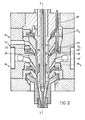
- the adjustment rings 741 to 74 3 corresponding respectively to the upper stage 10, to the middle stage 12 and to the lower stage 14 of the coextrusion head, each comprise a wall internal lateral 76, free from any contact with a fixed part, and an external lateral wall 75-78 in shape of a spherical zone which is applied against carrying surfaces 62, 62 'of a shape exactly complementary to that of the wall 75-78, and which are formed on two fixed and superimposed annular flanges 64, 64'.
- Said carrying surfaces belong to the same spherical zone centered on the axis xx of the coextrusion head and are strongly inclined towards the outlet of the head and towards the axis xx.
- Each of the adjustment rings has on its lateral side wall support means, such as an annular flange 81 situated substantially halfway up the ring and extending in an annular clearance 83 from the flange 64. On this flange bear the three adjustment screws or jacks, only one of which 89 is shown in FIG. 2.
- the adjustment rings are also provided with an internal wall 80 cut in a bevel, in the form of a spherical zone , conical, toric or ogival, which connects the lower edges of the internal and external lateral walls 76, 78.
- This bevelled wall 80 is at the same level as a contiguous wall of the adjacent fixed flange, with which it defines a narrow passage ring finger 84.
- the adjustment rings 74 1 to 74 3 are energetically applied against the adjacent bearing surfaces 62, 62 under the combined action of the high pressure of the material and the bearing force of the cylinders 89. Whatever or the inclination that the adjustment rings can have with respect to the axis xx of the coextrusion head, it is therefore ensured that no material leakage can occur either between the upper portion of the external wall 75 and the carrying surface 62, nor between the portion bottom of said outer wall 78 and the carrying surface 62 '. There is therefore no risk of infiltration of the material from one stage towards the neighboring clearance 83, and from there, along the jacks 89, towards the other stages.
Landscapes
- Engineering & Computer Science (AREA)
- Mechanical Engineering (AREA)
- Manufacturing & Machinery (AREA)
- Blow-Moulding Or Thermoforming Of Plastics Or The Like (AREA)
- Extrusion Moulding Of Plastics Or The Like (AREA)
- Processing And Handling Of Plastics And Other Materials For Molding In General (AREA)
Applications Claiming Priority (2)
| Application Number | Priority Date | Filing Date | Title |
|---|---|---|---|
| FR8320719A FR2557016A2 (fr) | 1983-12-23 | 1983-12-23 | Tete pour l'extrusion d'une paraison tubulaire a au moins une couche de matiere polymere |
| FR8320719 | 1983-12-23 |
Publications (2)
| Publication Number | Publication Date |
|---|---|
| EP0147324A2 true EP0147324A2 (de) | 1985-07-03 |
| EP0147324A3 EP0147324A3 (de) | 1985-08-28 |
Family
ID=9295525
Family Applications (1)
| Application Number | Title | Priority Date | Filing Date |
|---|---|---|---|
| EP84402700A Withdrawn EP0147324A3 (de) | 1983-12-23 | 1984-12-21 | Extrusionskopf zum Extrudieren eines Hohlformlings mit mindestens einer Kunststoffmaterialschicht |
Country Status (3)
| Country | Link |
|---|---|
| EP (1) | EP0147324A3 (de) |
| ES (1) | ES8606082A1 (de) |
| FR (1) | FR2557016A2 (de) |
Cited By (4)
| Publication number | Priority date | Publication date | Assignee | Title |
|---|---|---|---|---|
| DE3711026A1 (de) * | 1984-06-22 | 1988-10-20 | Osakeyhtioe Wiik & Hoglund Ab | Verfahren zur herstellung von verbundprodukten |
| EP0457991A1 (de) * | 1990-05-25 | 1991-11-27 | Hoover Universal,Inc. | Düse für ein mehrschichtiges Element mit verstellbaren Spalten |
| EP0549353A1 (de) * | 1991-12-27 | 1993-06-30 | Nippon Steel Chemical Co., Ltd. | Verfahren und Vorrichtung zum Blasformen von mehrschichtigen Gegenständen |
| WO2025237473A1 (de) * | 2024-05-14 | 2025-11-20 | VON ARDENNE Asset GmbH & Co. KG | Vakuumanordnung |
Families Citing this family (2)
| Publication number | Priority date | Publication date | Assignee | Title |
|---|---|---|---|---|
| DE3601345A1 (de) * | 1986-01-18 | 1987-07-23 | Reifenhaeuser Masch | Strangpresswerkzeug fuer die herstellung einer mehrschichtigen schlauchfolie |
| CN110355992B (zh) * | 2019-08-27 | 2021-06-01 | 安徽省春谷3D打印智能装备产业技术研究院有限公司 | 一种膨胀塑料管试制专用3d打印机喷头 |
Family Cites Families (3)
| Publication number | Priority date | Publication date | Assignee | Title |
|---|---|---|---|---|
| US2349178A (en) * | 1941-08-04 | 1944-05-16 | Plax Corp | Method of and apparatus for extruding and blowing organic plastic materials |
| JPS51147556A (en) * | 1975-06-13 | 1976-12-17 | Toyo Soda Mfg Co Ltd | Multiilayer rotary circular die |
| FR2503627A1 (fr) * | 1981-04-09 | 1982-10-15 | Raffinage Cie Francaise | Tete pour l'extrusion d'une paraison tubulaire a au moins une couche de matiere |
-
1983
- 1983-12-23 FR FR8320719A patent/FR2557016A2/fr active Pending
-
1984
- 1984-12-21 EP EP84402700A patent/EP0147324A3/de not_active Withdrawn
- 1984-12-21 ES ES538970A patent/ES8606082A1/es not_active Expired
Cited By (7)
| Publication number | Priority date | Publication date | Assignee | Title |
|---|---|---|---|---|
| DE3711026A1 (de) * | 1984-06-22 | 1988-10-20 | Osakeyhtioe Wiik & Hoglund Ab | Verfahren zur herstellung von verbundprodukten |
| EP0457991A1 (de) * | 1990-05-25 | 1991-11-27 | Hoover Universal,Inc. | Düse für ein mehrschichtiges Element mit verstellbaren Spalten |
| EP0549353A1 (de) * | 1991-12-27 | 1993-06-30 | Nippon Steel Chemical Co., Ltd. | Verfahren und Vorrichtung zum Blasformen von mehrschichtigen Gegenständen |
| US5460772A (en) * | 1991-12-27 | 1995-10-24 | Nippon Steel Chemical Co., Ltd. | Process for multilayer blow molding |
| US5667748A (en) * | 1991-12-27 | 1997-09-16 | Nippon Steel Chemical Co., Ltd. | Process and apparatus for multilayer blow molding and articles blow-molded therewith |
| US5718927A (en) * | 1991-12-27 | 1998-02-17 | Nippon Steel Chemical Co., Ltd. | Apparatus for multilayer blow molding |
| WO2025237473A1 (de) * | 2024-05-14 | 2025-11-20 | VON ARDENNE Asset GmbH & Co. KG | Vakuumanordnung |
Also Published As
| Publication number | Publication date |
|---|---|
| ES8606082A1 (es) | 1986-04-01 |
| FR2557016A2 (fr) | 1985-06-28 |
| EP0147324A3 (de) | 1985-08-28 |
| ES538970A0 (es) | 1986-04-01 |
Similar Documents
| Publication | Publication Date | Title |
|---|---|---|
| EP0096645B1 (de) | Dichtungsvorrichtung für ein Kugelkükenventil | |
| EP0147324A2 (de) | Extrusionskopf zum Extrudieren eines Hohlformlings mit mindestens einer Kunststoffmaterialschicht | |
| FR2700596A1 (fr) | Valve de barrage à dérivation réglable. | |
| CA2743401C (fr) | Bague pour palier hydrostatique ou hydrodynamique, machine hydraulique equipee d'une telle bague et procede de montage d'une telle bague sur un arbre | |
| FR2563600A1 (fr) | Joint de culasse | |
| FR2608081A1 (fr) | Dispositif et procede de blocage d'une piece | |
| FR2467620A1 (fr) | Dispositif de permeation | |
| FR2486429A1 (fr) | Procede permettant de reparer ou de remettre en etat des pieces d'usure refractaires de dispositifs d'obturation coulissants | |
| EP3982014B1 (de) | Dichtungsfuge mit einer schürze | |
| FR2716517A1 (fr) | Vanne rotative. | |
| FR2787155A1 (fr) | Agencement d'etancheite pour un joint homocinetique, et procede de fabrication correspondant | |
| FR2464208A1 (fr) | Systeme de canalisation pour le transport pneumatique de matieres pulverulentes ou granulaires | |
| FR2736134A1 (fr) | Dispositif d'etancheite, notamment pour machine de transformation de matiere plastique | |
| EP0428433B1 (de) | Vorrichtung zum Fixieren der Steuerstabsführungsplatte im Kernreaktordruckgefäss | |
| WO1992020480A1 (fr) | Ceinture d'etancheite d'un tube de coulee | |
| EP0783085B1 (de) | In einer Bohrung einsetzbarer flexibler Teil | |
| EP0020246B1 (de) | Vorrichtung zum Kühlen langer laminierter Wärmwalzprodukte | |
| FR2507733A1 (fr) | Vanne a passage direct | |
| FR2821914A1 (fr) | Vanne | |
| EP4452543A1 (de) | Form zum aluminothermischen schweissen von schienen | |
| BE1001778A3 (fr) | Dispositif d'obturation a cle tournante. | |
| FR3137866A1 (fr) | Procédé de fabrication par soudage d’un organe d’étanchéité dynamique, configuré pour équiper un dispositif joint tournant d’une installation d’exploitation de fluides, notamment sur une plateforme offshore | |
| EP1358414A1 (de) | Klappegehäuse mit eingerasteter manchette | |
| FR2519082A1 (fr) | Piston assemble a tete | |
| FR2573490A1 (fr) | Verin ayant un canal de transfert integre dans le cylindre |
Legal Events
| Date | Code | Title | Description |
|---|---|---|---|
| PUAI | Public reference made under article 153(3) epc to a published international application that has entered the european phase |
Free format text: ORIGINAL CODE: 0009012 |
|
| PUAL | Search report despatched |
Free format text: ORIGINAL CODE: 0009013 |
|
| AK | Designated contracting states |
Designated state(s): BE DE GB IT NL |
|
| AK | Designated contracting states |
Designated state(s): BE DE GB IT NL |
|
| 17P | Request for examination filed |
Effective date: 19851016 |
|
| 17Q | First examination report despatched |
Effective date: 19860526 |
|
| STAA | Information on the status of an ep patent application or granted ep patent |
Free format text: STATUS: THE APPLICATION IS DEEMED TO BE WITHDRAWN |
|
| 18D | Application deemed to be withdrawn |
Effective date: 19861005 |
|
| RIN1 | Information on inventor provided before grant (corrected) |
Inventor name: SIARD, MICHEL |