EP0147330B1 - Membranpumpe für die Brennstoffzufuhr eines Kraftfahrzeugmotors. - Google Patents
Membranpumpe für die Brennstoffzufuhr eines Kraftfahrzeugmotors. Download PDFInfo
- Publication number
- EP0147330B1 EP0147330B1 EP84402717A EP84402717A EP0147330B1 EP 0147330 B1 EP0147330 B1 EP 0147330B1 EP 84402717 A EP84402717 A EP 84402717A EP 84402717 A EP84402717 A EP 84402717A EP 0147330 B1 EP0147330 B1 EP 0147330B1
- Authority
- EP
- European Patent Office
- Prior art keywords
- cylindrical
- valve
- delivery
- holder
- induction
- Prior art date
- Legal status (The legal status is an assumption and is not a legal conclusion. Google has not performed a legal analysis and makes no representation as to the accuracy of the status listed.)
- Expired
Links
- 239000012528 membrane Substances 0.000 title description 12
- 239000000446 fuel Substances 0.000 title description 4
- 238000005192 partition Methods 0.000 claims description 11
- 230000002093 peripheral effect Effects 0.000 claims description 4
- 239000012815 thermoplastic material Substances 0.000 claims description 4
- 238000000465 moulding Methods 0.000 claims description 2
- 230000006698 induction Effects 0.000 claims 5
- 210000002445 nipple Anatomy 0.000 claims 2
- 238000002955 isolation Methods 0.000 claims 1
- 239000000203 mixture Substances 0.000 claims 1
- 238000002788 crimping Methods 0.000 description 3
- 239000003502 gasoline Substances 0.000 description 3
- 238000004519 manufacturing process Methods 0.000 description 3
- 238000007789 sealing Methods 0.000 description 3
- 230000000284 resting effect Effects 0.000 description 2
- 208000031968 Cadaver Diseases 0.000 description 1
- 230000006835 compression Effects 0.000 description 1
- 238000007906 compression Methods 0.000 description 1
- 230000007423 decrease Effects 0.000 description 1
- 230000003247 decreasing effect Effects 0.000 description 1
- 230000001419 dependent effect Effects 0.000 description 1
- 238000001035 drying Methods 0.000 description 1
- 238000001914 filtration Methods 0.000 description 1
- 239000002828 fuel tank Substances 0.000 description 1
- 239000002184 metal Substances 0.000 description 1
- 238000003825 pressing Methods 0.000 description 1
- 230000001737 promoting effect Effects 0.000 description 1
- 238000011144 upstream manufacturing Methods 0.000 description 1
- 238000003466 welding Methods 0.000 description 1
Images

Classifications
-
- F—MECHANICAL ENGINEERING; LIGHTING; HEATING; WEAPONS; BLASTING
- F04—POSITIVE - DISPLACEMENT MACHINES FOR LIQUIDS; PUMPS FOR LIQUIDS OR ELASTIC FLUIDS
- F04B—POSITIVE-DISPLACEMENT MACHINES FOR LIQUIDS; PUMPS
- F04B43/00—Machines, pumps, or pumping installations having flexible working members
- F04B43/02—Machines, pumps, or pumping installations having flexible working members having plate-like flexible members, e.g. diaphragms
-
- F—MECHANICAL ENGINEERING; LIGHTING; HEATING; WEAPONS; BLASTING
- F02—COMBUSTION ENGINES; HOT-GAS OR COMBUSTION-PRODUCT ENGINE PLANTS
- F02M—SUPPLYING COMBUSTION ENGINES IN GENERAL WITH COMBUSTIBLE MIXTURES OR CONSTITUENTS THEREOF
- F02M37/00—Apparatus or systems for feeding liquid fuel from storage containers to carburettors or fuel-injection apparatus; Arrangements for purifying liquid fuel specially adapted for, or arranged on, internal-combustion engines
- F02M37/04—Feeding by means of driven pumps
- F02M37/046—Arrangements for driving diaphragm-type pumps
Definitions
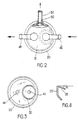
- the present invention relates to a diaphragm type pump, used in particular to supply petrol to the carburetor of a motor car engine.
- a diaphragm pump of the type described in the classifying part of claim 1 is known.
- a seal ensures the seal between the suction chamber and discharge chamber.
- This seal is confined for this purpose in a narrow annular channel defined on the one hand, in the radial direction, between the walls opposite the projecting portion of the valve holder and the first body, and on the other hand, in the direction axial, between shoulders formed on the valve holder and on the first body.
- the object of the present invention is to remedy these drawbacks by proposing a pump which can be produced in large series with large tolerances and therefore at a relatively low cost price, and which can be assembled automatically.
- the pump according to the invention conforms to the characterizing part of claim 1.
- the seal at the joint is not dependent on variations in the dimensions of the valve holder and of the first body, since the projecting part of the valve holder can always be more or less pressed inside the chamber d 'suction, and that the seal has all the space necessary to discharge axially.
- the pump according to the invention is much more economical than that according to the cited prior art, since on the one hand, the first body is made in one piece for molding a thermoplastic material instead of being made of metal , and on the other hand, because any unnecessary loss of thermoplastic material due to excess thicknesses is avoided, in particular in the zone of tangency between the internal partition and the cylindrical wall of the first body, and finally because it can be manufactured in very large series. It is indeed possible to manufacture a single model of first body for all types of engines, the pipes being then welded to the inlet and outlet ports with the desired orientation, imposed by the particular type of engine.
- the collar used according to patents US-A-3491 700 and FR-A-2 417 023 for assembling the first and second bodies is initially formed by a cylindrical ring of the same diameter as that of said bodies at their crimping rim, and the two edges of which are then folded inwards so that they pinch said crimping edges.
- the tightening thus carried out can loosen, in particular in the case where the membrane decreases in thickness as a result of drying out or loss of elasticity due to fatigue. Fuel leaks can then occur at the joint between the two bodies.
- the initially inclined branch of the flange would still continue to exert an elastic clamping action on said edges, and would make up for any play which would tend to form between the two bodies.
- the fuel pump 10 essentially comprises an upper body 12 and a lower body 14, both made of a thermoplastic material of good mechanical resistance and having good resistance to the relatively high temperatures which prevail under the hood of the car.
- the bodies 12 and 14 are constituted by substantially cylindrical containers, open at one end and the respective free edges of which are applied to one another, crushing between them the peripheral edge of a deformable membrane 16, for example made of rubber , and the peripheral edge of a rigid valve holder 18. To this end, the two bodies are secured by means of an annular flange 20 of elastic sheet, which is crimped on annular flanges 22, 24, formed respectively on said edges of the bodies.
- the flange initially has a section with three branches, the upper branch 26 which is intended to be applied against the horizontal shoulder 28 of the flange 22 of the upper body, is inclined internally from the horizontal by a small angle a.
- this branch deforms elastically to apply to the shoulder 28 by exerting on the flanges 22, 24 and therefore on the edges of the membrane 16 and of the valve holder 18 an elastic tightening which guarantees a perfect seal between the two bodies.
- the upper body 12 is divided internally by a substantially cylindrical partition 30 tangentially connecting to the wall of the body 12, in a suction chamber 32 inside said partition and in a discharge chamber 34 outside said partition.
- the discharge chamber internally has partial partitions, which, drawn in an appropriate manner, make it possible to isolate volumes which act as a damper promoting the flow rates.
- the valve holder 18 includes a portion which fits into the opening of the suction chamber 32, an O-ring 36 ensuring sealing. Said valve holder portion as well as the remaining portion which is opposite the delivery chamber are respectively provided with orifices, closed in a manner known per se, by valves 38, 40 loaded by springs 41. Upstream of the suction valve 38 is mounted a screen 43 for filtering the gasoline arriving from the tank.
- the upper body 12 has, on its bottom wall, two orifices 42 and 44, which open respectively into the suction chamber 32 and into the discharge chamber 34.
- an adjustable suction pipe 46 connected to the vehicle's fuel tank and an adjustable delivery pipe 48 connected to the carburetor.
- these pipes are welded at the time of assembly, with the orientation desired by the user.
- the upper body also has in its cylindrical wall an orifice 50 which opens into the delivery chamber and on which is fixed a tube 52 intended to bring the fuel back to the tank in the event of the car.
- the central portion of the membrane 16 is sandwiched between a support flange 54 and a counter plate 56 to which it is secured by means of a rivet 58.
- the flange carries an L-shaped arm 60 connected by a free-running link to the 'upper end of a pusher 62 which extends along the axis of the lower body 14.
- the pusher projects outside the lower body through an orifice formed in the bottom of the latter, a seal 64 ensuring the sealing at this orifice.
- the membrane-flange and counter-plate assembly is normally biased upwards in FIG. 1 by a compression spring 66 resting on the flange 54 and on the bottom of the lower body.
- the pusher 62 can be pressed inside the lower body, against the force of a spring 68 of greater hardness than that of the spring 66.
- the pusher can be actuated either by the eccentric of a motor shaft , or by a tilting lever.
- the pump is in the state shown in FIG. 1: the pusher 62 is brought into its low position by the return spring 68; the stop 70 of the pusher resting on the arm 60 lowers the assembly of the membrane 16, of the support flange 54 and of the counterplate 56.
- the cam pushes the pusher, said movable assembly being released, it is pushed upwards in FIG. 1 by the prestressed spring 66.
- the gasoline which is in the chamber 72 defined between the membrane 16 and the valve holder 18 is discharged through the valve 40 and the manifold. discharge 48 to the carburetor. r.
- the pump according to the invention is much more efficient, lighter, more economical than the best diaphragm pumps currently known on the market.
- it can be manufactured fully automatically in large series, since only one model has to be manufactured, the pipes being welded at the time of assembly, with the desired orientation.
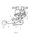
- the pump shown in FIG. 5 differs from that of FIG. 1 only in that the pusher 62 is directly fixed to the membrane 16, flange 54 and counter plate 56 assembly and that the pusher is actuated by a lever. tilting 76.
- the latter is pivotally mounted about an axis 78 and is urged to bear against a cam 80 of a drive shaft by a spring 82.
Landscapes
- Engineering & Computer Science (AREA)
- Mechanical Engineering (AREA)
- General Engineering & Computer Science (AREA)
- Chemical & Material Sciences (AREA)
- Combustion & Propulsion (AREA)
- Reciprocating Pumps (AREA)
Claims (4)
Applications Claiming Priority (2)
| Application Number | Priority Date | Filing Date | Title |
|---|---|---|---|
| FR8320928 | 1983-12-28 | ||
| FR8320928A FR2557639B1 (fr) | 1983-12-28 | 1983-12-28 | Pompe a membrane pour l'alimentation en essence d'un moteur de vehicule automobile et son procede d'assemblage |
Publications (2)
| Publication Number | Publication Date |
|---|---|
| EP0147330A1 EP0147330A1 (de) | 1985-07-03 |
| EP0147330B1 true EP0147330B1 (de) | 1988-08-17 |
Family
ID=9295652
Family Applications (1)
| Application Number | Title | Priority Date | Filing Date |
|---|---|---|---|
| EP84402717A Expired EP0147330B1 (de) | 1983-12-28 | 1984-12-26 | Membranpumpe für die Brennstoffzufuhr eines Kraftfahrzeugmotors. |
Country Status (5)
| Country | Link |
|---|---|
| EP (1) | EP0147330B1 (de) |
| DE (1) | DE3473493D1 (de) |
| ES (1) | ES8605614A1 (de) |
| FR (1) | FR2557639B1 (de) |
| PT (1) | PT79753A (de) |
Families Citing this family (6)
| Publication number | Priority date | Publication date | Assignee | Title |
|---|---|---|---|---|
| FR2608218B1 (fr) * | 1986-12-16 | 1989-04-07 | Hunsinger Emile | Pompe a membrane pour l'alimentation en essence d'un moteur de vehicule automobile et son procede de fabrication |
| ES2018567B3 (es) * | 1986-12-16 | 1991-04-16 | Emile Hunsinger | Bomba con membrana para la alimentacion en carburante de un motor termico y su proceso de fabricacion |
| FR2623253B1 (fr) * | 1987-11-13 | 1990-04-13 | Hunsinger Emile | Pompe d'alimentation en carburant d'un moteur thermique et son procede de fabrication |
| FR2722539B1 (fr) | 1994-07-12 | 1996-08-23 | Rivapompe Sa | Pompe mecanique a membrane a pression augmentee pour l'alimentation en carburant de moteurs thermiquues, et en particulier de moteur a injection |
| WO1997030283A1 (en) * | 1996-02-14 | 1997-08-21 | Mikuni Adec Corporation | Diaphragm-holding synthetic resin assembly |
| KR101605718B1 (ko) * | 2014-07-31 | 2016-03-24 | 세메스 주식회사 | 액 공급 유닛 및 이를 가지는 기판 처리 장치 |
Family Cites Families (13)
| Publication number | Priority date | Publication date | Assignee | Title |
|---|---|---|---|---|
| FR1121507A (fr) * | 1952-10-29 | 1956-08-20 | Carter Carburetor Corp | Pompe à carburant |
| US3252424A (en) * | 1960-01-15 | 1966-05-24 | Acf Ind Inc | Fuel systems |
| US3198128A (en) * | 1961-07-05 | 1965-08-03 | Acf Ind Inc | Mechanical pump |
| US3179055A (en) * | 1962-08-31 | 1965-04-20 | Acf Ind Inc | Fuel pump |
| US3491700A (en) * | 1967-03-21 | 1970-01-27 | Airtex Prod | Fuel pump |
| DE2159306B2 (de) * | 1970-12-17 | 1978-09-21 | Iao Industrie Riunite S.P.A., Turin (Italien) | Kraftstoffmembranpumpe für endotherme Maschinen |
| GB1476898A (en) * | 1975-05-05 | 1977-06-16 | Gen Motors France | Diaphragm pumps |
| JPS53106908A (en) * | 1977-02-28 | 1978-09-18 | Kyosan Denki Kk | Mechanical fuel pump for internal combustion engine |
| DE2901981A1 (de) * | 1978-02-09 | 1979-08-16 | Iao Industrie Riunite Spa | Membranpumpe zur treibstoff-foerderung, insbesondere fuer brennkraftmaschinen |
| FR2425555A1 (fr) * | 1978-05-08 | 1979-12-07 | Pn Sas Negro Et Co | Pompes pour l'alimentation en combustible pour moteurs a combustion interne |
| BR8004133A (pt) * | 1979-10-01 | 1981-04-22 | Acf Ind Inc | Bomba de combustivel |
| FR2512888A1 (fr) * | 1981-06-09 | 1983-03-18 | Siette Spa | Ensemble de pompage pour deux fluides differents, notamment de l'air et du carburant liquide, pour vehicules automobiles |
| IT8222121U1 (it) * | 1982-06-08 | 1983-12-08 | Siette Spa | Pompa a membrana, particolarmente per l'alimentazione del combustibile ad un motore a combustione interna |
-
1983
- 1983-12-28 FR FR8320928A patent/FR2557639B1/fr not_active Expired
-
1984
- 1984-12-26 EP EP84402717A patent/EP0147330B1/de not_active Expired
- 1984-12-26 DE DE8484402717T patent/DE3473493D1/de not_active Expired
- 1984-12-27 PT PT79753A patent/PT79753A/pt not_active IP Right Cessation
- 1984-12-27 ES ES539094A patent/ES8605614A1/es not_active Expired
Also Published As
| Publication number | Publication date |
|---|---|
| FR2557639B1 (fr) | 1988-06-24 |
| PT79753A (fr) | 1985-01-01 |
| FR2557639A1 (fr) | 1985-07-05 |
| ES539094A0 (es) | 1986-03-16 |
| DE3473493D1 (en) | 1988-09-22 |
| ES8605614A1 (es) | 1986-03-16 |
| EP0147330A1 (de) | 1985-07-03 |
Similar Documents
| Publication | Publication Date | Title |
|---|---|---|
| FR2733467A1 (fr) | Ensemble a clapet pour reservoir de carburant | |
| EP0147330B1 (de) | Membranpumpe für die Brennstoffzufuhr eines Kraftfahrzeugmotors. | |
| EP2256330B1 (de) | Ansauggeräuschdämpfer einer Brennkraftmaschine, sowie diesen umfassende Ansaugleitung | |
| FR2870017A1 (fr) | Soupape de regulation de pression | |
| FR2528116A1 (fr) | Pompe a diaphragme pour alimenter en carburant un moteur a combustion interne | |
| FR2839163A1 (fr) | Regulateur de pression notamment pour un systeme d'alimentation en carburant | |
| WO2002025094A1 (fr) | Dispositif de puisage et de jaugeage pour reservoir de carburant de vehicule automobile | |
| EP0702142B1 (de) | Pumpeneinheit enthaltend einen Druckregler, für Fahrzeugkraftstoffbehälter und Behälter damit ausgerüstet | |
| FR2730293A1 (fr) | Clapet antiretour charge par un ressort, comportant un organe d'obturation pousse par un element a ressort contre un siege de clapet dans un corps de clapet | |
| FR2667360A1 (fr) | Collecteur d'amenee de carburant pour une conduite d'amenee, destine a un moteur a combustion interne, du type presentant des soupages de dosage et d'atomisation de carburant actionnees electro-magnetiquement. | |
| EP0666415B1 (de) | Interner Druckregler im Flansch einer Druckerhöhungsvorrichtung | |
| FR2772837A1 (fr) | Carburateur a membrane pour un instrument de travail portatif guide manuellement | |
| EP0749860B1 (de) | Verbesserte Kraftstoffzufuhr-Einrichtung in einem Fahrzeugtank | |
| FR2708209A1 (fr) | Dispositif de nettoyage, notamment de dépoussiérage, pour un atomiseur. | |
| FR3012849A1 (fr) | Dispositif amortisseur de pulsations. | |
| FR2841634A1 (fr) | Briquet a gaz | |
| FR2656041A1 (fr) | Pompe mecanique pour l'alimentation en carburant d'un moteur a combustion interne, en particulier pour installation a injection. | |
| FR2599110A1 (fr) | Robinet equipe de clapets d'obturation et anti-retour | |
| FR2608218A1 (fr) | Pompe a membrane pour l'alimentation en essence d'un moteur de vehicule automobile et son procede de fabrication | |
| EP0275736B1 (de) | Membranpumpe für die Brennstoffzufuhr einer thermischen Maschine und Verfahren zu deren Herstellung | |
| EP4249787B1 (de) | Druckdämpfungsvorrichtung für einen flüssigkeitskreislauf | |
| WO2003053637A1 (fr) | Cartouche de gaz comprime pour appareil de fixation a reccord integre d'etancheite | |
| EP3814616A1 (de) | Leitvorrichtung in einer brennkammer | |
| EP1312405B1 (de) | Filterelement für Flüssigkeitfilter eines Verbrennungsmotors, Filter mit einem solchen Filterelement und Kraftfahrzeug mit einem solchen Filter | |
| FR3038359A1 (fr) | Soupape de securite pour aspirateur |
Legal Events
| Date | Code | Title | Description |
|---|---|---|---|
| PUAI | Public reference made under article 153(3) epc to a published international application that has entered the european phase |
Free format text: ORIGINAL CODE: 0009012 |
|
| AK | Designated contracting states |
Designated state(s): DE GB IT SE |
|
| 17P | Request for examination filed |
Effective date: 19850729 |
|
| 17Q | First examination report despatched |
Effective date: 19860320 |
|
| GRAA | (expected) grant |
Free format text: ORIGINAL CODE: 0009210 |
|
| AK | Designated contracting states |
Kind code of ref document: B1 Designated state(s): DE GB IT SE |
|
| REF | Corresponds to: |
Ref document number: 3473493 Country of ref document: DE Date of ref document: 19880922 |
|
| ITF | It: translation for a ep patent filed | ||
| GBT | Gb: translation of ep patent filed (gb section 77(6)(a)/1977) | ||
| PLBE | No opposition filed within time limit |
Free format text: ORIGINAL CODE: 0009261 |
|
| STAA | Information on the status of an ep patent application or granted ep patent |
Free format text: STATUS: NO OPPOSITION FILED WITHIN TIME LIMIT |
|
| 26N | No opposition filed | ||
| ITTA | It: last paid annual fee | ||
| EAL | Se: european patent in force in sweden |
Ref document number: 84402717.7 |
|
| PGFP | Annual fee paid to national office [announced via postgrant information from national office to epo] |
Ref country code: SE Payment date: 19961209 Year of fee payment: 13 |
|
| PGFP | Annual fee paid to national office [announced via postgrant information from national office to epo] |
Ref country code: DE Payment date: 19961219 Year of fee payment: 13 |
|
| PGFP | Annual fee paid to national office [announced via postgrant information from national office to epo] |
Ref country code: GB Payment date: 19961224 Year of fee payment: 13 |
|
| PG25 | Lapsed in a contracting state [announced via postgrant information from national office to epo] |
Ref country code: GB Free format text: LAPSE BECAUSE OF NON-PAYMENT OF DUE FEES Effective date: 19971226 |
|
| PG25 | Lapsed in a contracting state [announced via postgrant information from national office to epo] |
Ref country code: SE Free format text: LAPSE BECAUSE OF NON-PAYMENT OF DUE FEES Effective date: 19971227 |
|
| GBPC | Gb: european patent ceased through non-payment of renewal fee |
Effective date: 19971226 |
|
| PG25 | Lapsed in a contracting state [announced via postgrant information from national office to epo] |
Ref country code: DE Free format text: LAPSE BECAUSE OF NON-PAYMENT OF DUE FEES Effective date: 19980901 |
|
| EUG | Se: european patent has lapsed |
Ref document number: 84402717.7 |