EP0147444B1 - Device for positioning the end of an optical fibre in a sleeve - Google Patents
Device for positioning the end of an optical fibre in a sleeve Download PDFInfo
- Publication number
- EP0147444B1 EP0147444B1 EP84902379A EP84902379A EP0147444B1 EP 0147444 B1 EP0147444 B1 EP 0147444B1 EP 84902379 A EP84902379 A EP 84902379A EP 84902379 A EP84902379 A EP 84902379A EP 0147444 B1 EP0147444 B1 EP 0147444B1
- Authority
- EP
- European Patent Office
- Prior art keywords
- sleeve
- rods
- passage
- intended
- fibre
- Prior art date
- Legal status (The legal status is an assumption and is not a legal conclusion. Google has not performed a legal analysis and makes no representation as to the accuracy of the status listed.)
- Expired
Links
Images
Classifications
-
- G—PHYSICS
- G02—OPTICS
- G02B—OPTICAL ELEMENTS, SYSTEMS OR APPARATUS
- G02B6/00—Light guides; Structural details of arrangements comprising light guides and other optical elements, e.g. couplings
- G02B6/24—Coupling light guides
- G02B6/36—Mechanical coupling means
- G02B6/38—Mechanical coupling means having fibre to fibre mating means
- G02B6/3801—Permanent connections, i.e. wherein fibres are kept aligned by mechanical means
- G02B6/3803—Adjustment or alignment devices for alignment prior to splicing
-
- G—PHYSICS
- G02—OPTICS
- G02B—OPTICAL ELEMENTS, SYSTEMS OR APPARATUS
- G02B6/00—Light guides; Structural details of arrangements comprising light guides and other optical elements, e.g. couplings
- G02B6/24—Coupling light guides
- G02B6/36—Mechanical coupling means
- G02B6/38—Mechanical coupling means having fibre to fibre mating means
- G02B6/3807—Dismountable connectors, i.e. comprising plugs
- G02B6/3833—Details of mounting fibres in ferrules; Assembly methods; Manufacture
- G02B6/3834—Means for centering or aligning the light guide within the ferrule
- G02B6/3841—Means for centering or aligning the light guide within the ferrule using rods, balls for light guides
Definitions
- the present invention relates to a device for positioning the end of an optical fibre in a sleeve comprising an assembly of at least three mutually parallel rods, forming between themselves a passage accommodating the fibre end, one end of the assembly being intended for accommodation in the sleeve.
- the object of the present invention is to provide an apparatus of the kind described in the introduction that is easy and cheap to manufacture, and that allows precise positioning of an optical fibre, irrespective of their diameter.
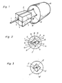
- Figure 1 is a perspective view of an embodiment of a device in accordance with the invention
- Figure 2 is an end view of a device according to Figure 1
- Figure 3 is an end view of a second embodiment of the device in accordance with the invention.
- Figure 1 illustrates an embodiment of a device in accordance with the invention for positioning the end of an optical fibre 1 in a sleeve 10.
- the illustrated embodiment includes four mutually parallel rods 2, 3, 4 and 5, forming between themselves a passage accommodating the end of the fibre 1, the sleeve 10 accommodating one end of each rod.
- Each of the rods 2-5 has two planar adjacent surfaces, and in the illustrated case these surfaces meet each other at right-angles along a longitudinal edge 6, 7, 8, and 9, as in Figure 2.
- one of the two planar surfaces on the respective rod engages against one of the two planar surfaces on a juxtaposed rod such that the longitudinal edge 6-9 of the respective rod 2-5 extend parallel to, and are distributed around the central axis of the passage for the fibre 1.
- the rods 2-5 are mutually, displaceable in relation to this axis by sliding against their mutually engaging surfaces in order to change the size of the passage so as to enable the accommodation of fibres having different diameters.
- the fibre and its surrounding rods may be glued to each other to ensure fixation of the rods with the fibre.
- the ends of the rods 2-5 intended for insertion in the sleeve are formed with a third planar surface 11, 12, 13 and 14, which is preferably parallel to the longitudinal edge of the respective rod, and, in the present case, forms an angle of 45° with the other planar surfaces which intersect other at right-angles, each of which is contiguous with a corresponding surface on an adjacent rod.
- the other ends of the rods are formed with a quadratic section in the illustrated embodiment, but may of course be formed in some other way.
- the ends of the rods 2-5 inserted in the sleeve 10 are shaped so as to have cross-sections in the form of identical isosceles right-angular triangles.
- the interiorwalls of the sleeve 10 enclose a cavity of substantially quadratic cross-section.
- the sleeve is provided with longitudinal recesses 15, 16, 17 and 18 between adjacent mutually perpendicular interior walls. The size of the recesses 15-18 depends on the diameter of the fibre 1 that is to be placed between the rods 2-5.
- the sleeve 10 has a cavity of purely quadratic cross-section for accommodating the rod ends. These, denoted 2', 3', 4' and 5', are chamfered in a manner illustrated in Figure 3, to enable their reception in the sleeve 10' when mutually displaced, thus enabling fibres of different diameters to be placed between the rods.
- the rod ends inserted in the sleeve naturally do not need to be identical, but the advantage in doing this is that the set of rods may be inserted in the sleeve in any order.
- a similar set of rods may be inserted in the other end of the sleeve 10 illustrated in Figure 1, to obtain optical coupling between the fibre 1 and the not illustrated fibre in the other set of rods.
- the invention is naturally not confined to the use of four rods, it being possible to use three, five or more. In all cases, however, the sum of the angles between the respective rods' adjacent surfaces forming the edges 6-9 must attain 360°C. In the case of three identical rods, this angle will thus be 120°, while the angle between the third planar surface of the respective rod and each of its other two flat surfaces will be 60°.
Landscapes
- Physics & Mathematics (AREA)
- General Physics & Mathematics (AREA)
- Optics & Photonics (AREA)
- Mechanical Coupling Of Light Guides (AREA)
- Packaging Of Annular Or Rod-Shaped Articles, Wearing Apparel, Cassettes, Or The Like (AREA)
- Light Guides In General And Applications Therefor (AREA)
Applications Claiming Priority (2)
| Application Number | Priority Date | Filing Date | Title |
|---|---|---|---|
| SE8302980A SE436940B (sv) | 1983-05-26 | 1983-05-26 | Anordning for legesfixering av enden av en optisk fiber i en hylsa |
| SE8302980 | 1983-06-14 |
Publications (2)
| Publication Number | Publication Date |
|---|---|
| EP0147444A1 EP0147444A1 (en) | 1985-07-10 |
| EP0147444B1 true EP0147444B1 (en) | 1988-09-07 |
Family
ID=20351339
Family Applications (1)
| Application Number | Title | Priority Date | Filing Date |
|---|---|---|---|
| EP84902379A Expired EP0147444B1 (en) | 1983-05-26 | 1984-05-25 | Device for positioning the end of an optical fibre in a sleeve |
Country Status (10)
| Country | Link |
|---|---|
| US (1) | US4725118A (it) |
| EP (1) | EP0147444B1 (it) |
| JP (1) | JPS60501577A (it) |
| DE (1) | DE3473938D1 (it) |
| DK (1) | DK67485A (it) |
| FI (1) | FI850339A7 (it) |
| IT (1) | IT1174168B (it) |
| NO (1) | NO850352L (it) |
| SE (1) | SE436940B (it) |
| WO (1) | WO1985000061A1 (it) |
Families Citing this family (13)
| Publication number | Priority date | Publication date | Assignee | Title |
|---|---|---|---|---|
| US4968109A (en) * | 1984-04-19 | 1990-11-06 | E. I. Du Pont De Nemours And Company | Press bonding apparatus method for terminating an optical fiber with a plastically deformable termination member |
| US4865412A (en) * | 1988-04-18 | 1989-09-12 | Minnesota Mining And Manufacturing Company | Connector for splicing optical fiber cables |
| US4818055A (en) * | 1988-04-18 | 1989-04-04 | Minnesota Mining And Manufacturing Company | Optical fiber splice connector |
| JP2855467B2 (ja) * | 1990-05-16 | 1999-02-10 | ヒロセ電機株式会社 | 光ファイバコネクタ端末とその製造方法 |
| JP2855468B2 (ja) * | 1990-05-16 | 1999-02-10 | ヒロセ電機株式会社 | 光フアイバコネクタ端末とその製造方法 |
| JP2855466B2 (ja) * | 1990-05-16 | 1999-02-10 | ヒロセ電機株式会社 | 光ファイバコネクタ端末とその製造方法 |
| JP2921701B2 (ja) * | 1990-05-16 | 1999-07-19 | ヒロセ電機株式会社 | 光ファイバコネクタ端末 |
| JP2855465B2 (ja) * | 1990-05-16 | 1999-02-10 | ヒロセ電機株式会社 | 光ファイバコネクタ端末とその製造方法 |
| JP2921700B2 (ja) * | 1990-05-16 | 1999-07-19 | ヒロセ電機株式会社 | 多芯光ファイバコネクタ端末とその製造方法 |
| US5337385A (en) * | 1991-03-01 | 1994-08-09 | The Whitaker Corporation | Optical waveguide terminating device |
| US5425119A (en) * | 1993-09-23 | 1995-06-13 | Minnesota Mining And Manufacturing Company | Connector strain relief for optical fiber |
| US6139195A (en) * | 1996-05-22 | 2000-10-31 | Minnesota Mining And Manufacturing Company | Strain relief for a coated optical fiber in a connector |
| JP3710083B2 (ja) * | 1999-03-17 | 2005-10-26 | 日本板硝子株式会社 | 光ファイバ接続用ガラス部品の製造方法 |
Family Cites Families (6)
| Publication number | Priority date | Publication date | Assignee | Title |
|---|---|---|---|---|
| JPS5370835A (en) * | 1976-12-07 | 1978-06-23 | Fujitsu Ltd | Optical fiber connector |
| FR2387462A1 (fr) * | 1977-04-13 | 1978-11-10 | Thomson Csf | Embout de positionnement pour fibre optique, connecteur comportant un tel embout et procede d'ajustage d'une connexion entre fibres |
| NL184342C (nl) * | 1978-05-05 | 1989-06-16 | Philips Nv | Losneembare koppeling voor lichtgeleidende vezels. |
| FR2440005A1 (fr) * | 1978-10-27 | 1980-05-23 | Socapex | Embout de connecteur pour monofibre optique, et procede de fixation d'un tel embout sur une telle monofibre |
| US4391487A (en) * | 1981-01-07 | 1983-07-05 | Gte Laboratories Incorporated | Optical fiber centering device |
| US4668045A (en) * | 1983-01-03 | 1987-05-26 | Gte Laboratories Incorporated | Optical fiber centering device |
-
1983
- 1983-05-26 SE SE8302980A patent/SE436940B/sv not_active IP Right Cessation
-
1984
- 1984-05-25 JP JP59502346A patent/JPS60501577A/ja active Pending
- 1984-05-25 DE DE8484902379T patent/DE3473938D1/de not_active Expired
- 1984-05-25 FI FI850339A patent/FI850339A7/fi not_active Application Discontinuation
- 1984-05-25 US US06/692,045 patent/US4725118A/en not_active Expired - Fee Related
- 1984-05-25 EP EP84902379A patent/EP0147444B1/en not_active Expired
- 1984-05-25 WO PCT/SE1984/000200 patent/WO1985000061A1/en not_active Ceased
- 1984-06-11 IT IT8421348A patent/IT1174168B/it active
-
1985
- 1985-01-29 NO NO85850352A patent/NO850352L/no unknown
- 1985-02-13 DK DK67485A patent/DK67485A/da not_active Application Discontinuation
Also Published As
| Publication number | Publication date |
|---|---|
| DE3473938D1 (en) | 1988-10-13 |
| DK67485D0 (da) | 1985-02-13 |
| EP0147444A1 (en) | 1985-07-10 |
| FI850339A0 (fi) | 1985-01-25 |
| FI850339L (fi) | 1985-01-25 |
| DK67485A (da) | 1985-02-13 |
| FI850339A7 (fi) | 1985-01-25 |
| JPS60501577A (ja) | 1985-09-19 |
| WO1985000061A1 (en) | 1985-01-03 |
| IT8421348A0 (it) | 1984-06-11 |
| SE8302980L (sv) | 1984-12-15 |
| NO850352L (no) | 1985-01-29 |
| IT1174168B (it) | 1987-07-01 |
| US4725118A (en) | 1988-02-16 |
| SE8302980D0 (sv) | 1983-05-26 |
| SE436940B (sv) | 1985-01-28 |
Similar Documents
| Publication | Publication Date | Title |
|---|---|---|
| EP0147444B1 (en) | Device for positioning the end of an optical fibre in a sleeve | |
| DE69232421T2 (de) | Stecker für vieladrige optische Verbindung mit niedrigem Reflexions- und niedrigem Dämpfungsverlust | |
| EP0338759B1 (en) | Stamped precision lightguide interconnect centering element | |
| DE2512330C3 (de) | Steckverbindung für ummantelte Lichtleitfasern aus Quarzglas oder Glas | |
| DE2622607C3 (de) | Selbstzentrierende Steckverbindungsanordnung für Lichtwellenleiter | |
| US5351371A (en) | Rod-securing clip for use in optical fiber three-rod connectors | |
| US3936145A (en) | Fiber optic alignment sleeve | |
| CA1095759A (en) | Hermaphrodite optical fiber connector | |
| DE2718006A1 (de) | Verbinder fuer lichtleiter | |
| HK1007601B (en) | Stamped precision lightguide interconnect centering element | |
| DE3229571A1 (de) | Optischer sternkoppler | |
| US20030044124A1 (en) | Convertible multi-diameter sleeve for optical fiber connectors | |
| GB2033758A (en) | Fracture fixing appliance | |
| CA2009119A1 (en) | Mechanical connection for polarization-maintaining optical fiber and methods of making | |
| DE2703191C2 (de) | Lichtleitfaserumschalter | |
| EP0423928B1 (en) | Multi-ferrule structure | |
| US4807957A (en) | Connector for optical fibers | |
| US4927229A (en) | Optical cable coupling adapter | |
| EP0243962B1 (en) | A connector housing for an optical fiber cable | |
| EP0109424B1 (en) | Apparatus for mutually aligning the ends of two optical fibres that are to be connected | |
| DE69011311T2 (de) | Wiederverwendbarer faseroptischer mechanischer Verbinder. | |
| GB2210511A (en) | A waveguide twist assembly | |
| JPS6128909A (ja) | 光コネクタ | |
| EP0098548A2 (de) | Einrichtung und Verfahren zur Herstellung einer mechanischen, nicht lösbaren Spleissverbindung zweier Lichtwellenleiter aus Quarzglas | |
| SU1721573A1 (ru) | Соединительный элемент |
Legal Events
| Date | Code | Title | Description |
|---|---|---|---|
| PUAI | Public reference made under article 153(3) epc to a published international application that has entered the european phase |
Free format text: ORIGINAL CODE: 0009012 |
|
| AK | Designated contracting states |
Designated state(s): CH DE FR GB LI NL |
|
| 17P | Request for examination filed |
Effective date: 19850116 |
|
| 17Q | First examination report despatched |
Effective date: 19870731 |
|
| GRAA | (expected) grant |
Free format text: ORIGINAL CODE: 0009210 |
|
| AK | Designated contracting states |
Kind code of ref document: B1 Designated state(s): CH DE FR GB LI NL |
|
| PG25 | Lapsed in a contracting state [announced via postgrant information from national office to epo] |
Ref country code: NL Effective date: 19880907 Ref country code: LI Effective date: 19880907 Ref country code: CH Effective date: 19880907 |
|
| REF | Corresponds to: |
Ref document number: 3473938 Country of ref document: DE Date of ref document: 19881013 |
|
| REG | Reference to a national code |
Ref country code: CH Ref legal event code: PL |
|
| ET | Fr: translation filed | ||
| NLV1 | Nl: lapsed or annulled due to failure to fulfill the requirements of art. 29p and 29m of the patents act | ||
| PG25 | Lapsed in a contracting state [announced via postgrant information from national office to epo] |
Ref country code: GB Effective date: 19890525 |
|
| PLBE | No opposition filed within time limit |
Free format text: ORIGINAL CODE: 0009261 |
|
| STAA | Information on the status of an ep patent application or granted ep patent |
Free format text: STATUS: NO OPPOSITION FILED WITHIN TIME LIMIT |
|
| 26N | No opposition filed | ||
| GBPC | Gb: european patent ceased through non-payment of renewal fee | ||
| PG25 | Lapsed in a contracting state [announced via postgrant information from national office to epo] |
Ref country code: FR Free format text: LAPSE BECAUSE OF NON-PAYMENT OF DUE FEES Effective date: 19900131 |
|
| PG25 | Lapsed in a contracting state [announced via postgrant information from national office to epo] |
Ref country code: DE Effective date: 19900201 |
|
| REG | Reference to a national code |
Ref country code: FR Ref legal event code: ST |