EP0147449B1 - Ameliorations relatives a des separateurs de rayons optiques - Google Patents
Ameliorations relatives a des separateurs de rayons optiques Download PDFInfo
- Publication number
- EP0147449B1 EP0147449B1 EP84902462A EP84902462A EP0147449B1 EP 0147449 B1 EP0147449 B1 EP 0147449B1 EP 84902462 A EP84902462 A EP 84902462A EP 84902462 A EP84902462 A EP 84902462A EP 0147449 B1 EP0147449 B1 EP 0147449B1
- Authority
- EP
- European Patent Office
- Prior art keywords
- light
- beam splitter
- transmitted
- original
- coma
- Prior art date
- Legal status (The legal status is an assumption and is not a legal conclusion. Google has not performed a legal analysis and makes no representation as to the accuracy of the status listed.)
- Expired
Links
- 230000003287 optical effect Effects 0.000 title claims abstract description 16
- 230000004075 alteration Effects 0.000 claims abstract description 26
- 206010010071 Coma Diseases 0.000 claims abstract description 25
- 201000009310 astigmatism Diseases 0.000 claims abstract description 22
- 238000003491 array Methods 0.000 claims description 12
- 239000003086 colorant Substances 0.000 claims description 8
- 230000005855 radiation Effects 0.000 claims description 3
- 238000001444 catalytic combustion detection Methods 0.000 claims 3
- 238000010191 image analysis Methods 0.000 abstract description 2
- 238000000926 separation method Methods 0.000 abstract description 2
- 230000006698 induction Effects 0.000 abstract 1
- 230000035945 sensitivity Effects 0.000 abstract 1
- 230000005540 biological transmission Effects 0.000 description 5
- 239000011248 coating agent Substances 0.000 description 5
- 238000000576 coating method Methods 0.000 description 5
- 238000005286 illumination Methods 0.000 description 4
- 238000004458 analytical method Methods 0.000 description 2
- 239000000975 dye Substances 0.000 description 2
- 230000003595 spectral effect Effects 0.000 description 2
- 239000000654 additive Substances 0.000 description 1
- 230000000996 additive effect Effects 0.000 description 1
- 230000015556 catabolic process Effects 0.000 description 1
- 230000007812 deficiency Effects 0.000 description 1
- 238000006731 degradation reaction Methods 0.000 description 1
- 239000011521 glass Substances 0.000 description 1
- 238000003384 imaging method Methods 0.000 description 1
- 239000000463 material Substances 0.000 description 1
- 230000027272 reproductive process Effects 0.000 description 1
Images

Classifications
-
- G—PHYSICS
- G02—OPTICS
- G02B—OPTICAL ELEMENTS, SYSTEMS OR APPARATUS
- G02B27/00—Optical systems or apparatus not provided for by any of the groups G02B1/00 - G02B26/00, G02B30/00
- G02B27/0018—Optical systems or apparatus not provided for by any of the groups G02B1/00 - G02B26/00, G02B30/00 with means for preventing ghost images
-
- H—ELECTRICITY
- H04—ELECTRIC COMMUNICATION TECHNIQUE
- H04N—PICTORIAL COMMUNICATION, e.g. TELEVISION
- H04N23/00—Cameras or camera modules comprising electronic image sensors; Control thereof
- H04N23/10—Cameras or camera modules comprising electronic image sensors; Control thereof for generating image signals from different wavelengths
- H04N23/13—Cameras or camera modules comprising electronic image sensors; Control thereof for generating image signals from different wavelengths with multiple sensors
- H04N23/16—Optical arrangements associated therewith, e.g. for beam-splitting or for colour correction
Definitions
- image analysing devices it is conventional to scan, point to point, an original with a spot of light and to analyse the modulated light transmitted by or reflected from the original to determine its spectral content and brightness.
- the analysis is generally effected by splitting the modulated light into three colours, for example red, green and blue and to measure the amount of light of each of the colours by means of respective photoresponsive devices.
- the scanning can be effected by means of a raster on the face plate of a cathode ray tube which is imaged onto the original.
- the point of light may be caused to move across the original respectively in one direction whilst the original is moved (at a slower rate) orthogonally in its own plane.
- the modulated and split light is collected and directed onto the respective photoresponsive devices and signals therefrom are representative of the colour content of the original on a point to point basis.
- signals can be stored and/or used indirectly or directly in a reproductive process.
- the beam splitting may be effected by semi- reflective mirrors which may be dichroic and/or which may be followed by colour filters so that each photoresponsive device receives only light of one of the three colours.
- a conventional beam splitter is in the form shown in Fig. 1 of the accompanying drawings and comprises three prisms two of which have dichroic filters coated on one of their faces. Such a beam splitter is costly and has inherent disadvantages but is of the kind normally used when two dimensional scanning of an original is effected such as in a television camera.
- Linear charge coupled devices have now been developed.
- the individual cells of the array are small enough to give a pixel size providing acceptable resolution.
- An illuminated line of an original to be scanned is imaged on the array.
- Three such arrays, with an appropriate beam splitter are used.
- the original is preferably moved so that successive lines thereof are imaged on the arrays.
- a linear CCD array may typically be 10 to 15 mm long and contain 1000 cells in the linear array.
- Each pixel is then 1 thousandth of the width of the original in the direction of the line of illumination.
- the light received by each cell of the CCD derives from an area of the original no greater than 0.25 mm (and preferably of the order of 0.025 mm) length in the direction of the line of illumination.
- the present invention seeks to overcome the aforesaid disadvantages in a simple yet inexpensive manner whilst fully utilising the advantages afforded by the newly developed linear charge coupled device arrays.
- US-A-3293357 shows an optical beam splitter for use in analysing the image content of an original by splitting light transmitted through or reflected from the original into three colours by means of dichroic mirrors mounted on transparent support media.
- the present invention provides an optical beam splitter for use in analysing the image content of an original by splitting light transmitted through or reflected from the original into three colours by means of dichroic mirrors mounted on transparent support media, wherein each transparent support medium induces transverse chromatic aberration and coma in the rays of light transmitted thereby, characterized in that the beam splitter includes at least one further transparent plate, such that light transmitted by the beam splitter to respective linear charge coupled device arrays has induced therein either (1) no coma and transverse chromatic aberration contributions, or (2) one or more coma and transverse chromatic aberration contributions of one polarity having respective total magnitudes and one or more coma and transverse chromatic aberration contributions of opposite polarity having the same respective total magnitudes.
- the beam splitter preferably further includes a respective terminal astigmatism correcting lens in each transmitted light path, before the respective CCD array, for focussing a fully corrected line of light thereonto.
- the mirrors being inclined at equal and opposite angles to the axis of the system, and one further transparent plate, light of a first colour being reflected from one dichroic mirror and light of second and third colours being transmitted thereby, light of the second colour being reflected by the other dichroic mirror and transmitted by the further transparent plate, and light of the third colour being transmitted by said other dichroic mirror such that light of the first colour is not transmitted and has zero coma, transverse chromatic aberration or astigmatism induced therein, light of the second colour has two equal and opposite amounts of coma and transverse chromatic aberration induced therein in its passage through the transparent support medium of said one dichroic mirror and through the transparent plate, and light of the third colour has two equal and opposite amounts of coma and transverse chromatic aberration induced therein on passage through the transparent support media of both of said dichroic mirrors.
- Each terminal astigmatism correcting lens may be in the form of a piano-convex cylindrical lens having its axis parallel to the length of the respective linear array of CCDs.
- the transparent support media and the transparent plate may be arranged to be sufficiently thick that ghost images caused by internal reflection are imaged at a location remote from the sensitive surface of the charge coupled devices.
- Infrared light inherently produced by most light sources, is not absorbed to any great extent by photographic dyes. It is necessary to ensure that that CCD array which would normally receive infrared light (the "red” array) does not do so. This is ensured by providing an infrared reflecting surface, for example, on the transparent plate.
- optical paths may include lenses working at apertures of f4 or larger and the resolution of the image is within the commercially acceptable range utilising presently available arrays of charge coupled devices.
- optical beam splitter in accordance with the present invention is useful in an image analysing apparatus instead of the relatively expensive beam splitter shown in Fig. 1.
- Light modulated by transmission through the original is ultimately focussed onto linear arrays of charge coupled devices (CCDs) responsive respectively to light of a particular colour.
- CCDs charge coupled devices
- the beam splitter of the present invention is interposed in between the original and the linear CCD arrays.
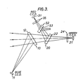
- the beam splitter comprises a first dichroic mirror 10 having a dichroic coating on the front surface of a transparent supporting medium 12 which coating reflects blue light to a first linear CCD array 11 extending at right angles to the plane of the drawing.
- the image modulated light is focussed onto the array.
- the CCD array 11 is sensitive to blue light and may have an appropriate correcting filter (not shown) in the path thereto after the dichroic mirror 10 to overcome spectral deficiencies of the dichroic coating.
- Red and green image modulated light impinging on the dichroic surface of the mirror 10 is transmitted thereby and passes through the transparent supporting medium 12. In so doing, transverse chromatic aberration, coma and astigmatism are induced in the image rays.
- the medium 12 is made sufficiently thick that the first and subsequent order ghost images are displaced sufficiently from the optical path so as to be imaged parallel to but displaced from the respective linear CCD array.
- the transmitted red and green light then impinge on the surface of a second dichroic mirror 20 having a dichroic coating on its surface which reflects red light and transmits green light which passes through the transparent support medium 22.
- Coma, astigmatism and transverse chromatic aberration are induced in the transmitted green light but because the transparent supporting medium 22 is of the same material and thickness as but oppositely inclined to the medium 12, the transverse chromatic aberration and coma induced are equal and opposite to those induced on the transmission through the medium 12 and are therefore corrected.
- Astigmatism due to light transmission through both the media 12 and 22 is additive and the image, in one plane, would not be in focus at the same distance from the medium 22 as the image in the plane at right angles thereto.
- a terminal astigmatism correcting lens 24 in the form of a piano-convex cylindrical lens of axis parallel to the length of the array is therefore interposed between the medium 22 and the CCD array 21 so that a fully corrected accurately focussed image of the line of green light from the original impinges on the CCD array 21. Any ghost images produced by internal reflection in the medium 22 are focussed as a line parallel to but displaced from the linear CCD array 21. As in the case of the "Blue" CCD array, appropriate correcting filters may be interposed between the medium 22 and the CCD array 21.
- the image modulated red light is reflected from the surface of the dichroic mirror 20 and, as this red light has only passed through the plate 12, an oppositely inclined transparent plate 32 is located such that the reflected red light passes therethrough.
- an oppositely inclined transparent plate 32 is located such that the reflected red light passes therethrough.
- equal and opposite transverse chromatic abberation and coma are induced to that induced by the medium 12.
- coma and transverse chromatic aberration are corrected.
- further astigmatism is induced on transmission through the plate 32 and an astigmatism correcting lens 35 (similar to the lens 24) is located so that the red light passing through the plate 32 is fully corrected and can be accurately focussed onto the sensitive surface of a "red" CCD array 31.
- any ghost images caused by the plate 32 are focussed as line images parallel to but displaced from the array 31.
- Infrared light (which is not absorbed by photographic dyes and hence is unmodulated by the image on the original) is normally reflected by the surface of the dichroic mirror 20 and would normally fall upon the "red" CCD array 31.
- CCDs are sensitive to infrared radiation.
- the transparent plate 32 has a dichroic coating on the surface 33 thereof which reflects infrared radiation but transmits image modulated red light.
- medium 12 and the medium 22 and the medium 12 and the plate 32 are of thickness and refractive index such that each induces an equal and opposite amount of coma and transverse chromatic aberration for all rays passing through each pair.
- the support media and the plate are preferably of glass and are each of such thickness (see Fig. 2) that adequate separation takes place between desired and first and subsequent order ghost images generated by internal reflection.
- Lenses used in the system can work at apertures of f4 and greater. In this way, linear CCD arrays can be used for image analysis without any optical degradation which would cause incorrect signals and consequent loss of image quality in any reproduction.
Landscapes
- Physics & Mathematics (AREA)
- General Physics & Mathematics (AREA)
- Optics & Photonics (AREA)
- Engineering & Computer Science (AREA)
- Multimedia (AREA)
- Signal Processing (AREA)
- Color Television Image Signal Generators (AREA)
- Facsimile Scanning Arrangements (AREA)
Abstract
Claims (7)
Applications Claiming Priority (2)
| Application Number | Priority Date | Filing Date | Title |
|---|---|---|---|
| GB8316402 | 1983-06-16 | ||
| GB838316402A GB8316402D0 (en) | 1983-06-16 | 1983-06-16 | Optical beam splitters |
Publications (2)
| Publication Number | Publication Date |
|---|---|
| EP0147449A1 EP0147449A1 (fr) | 1985-07-10 |
| EP0147449B1 true EP0147449B1 (fr) | 1988-03-02 |
Family
ID=10544311
Family Applications (1)
| Application Number | Title | Priority Date | Filing Date |
|---|---|---|---|
| EP84902462A Expired EP0147449B1 (fr) | 1983-06-16 | 1984-06-13 | Ameliorations relatives a des separateurs de rayons optiques |
Country Status (5)
| Country | Link |
|---|---|
| EP (1) | EP0147449B1 (fr) |
| JP (1) | JPS60501586A (fr) |
| DE (1) | DE3469667D1 (fr) |
| GB (1) | GB8316402D0 (fr) |
| WO (1) | WO1985000083A1 (fr) |
Families Citing this family (1)
| Publication number | Priority date | Publication date | Assignee | Title |
|---|---|---|---|---|
| FR2617293B1 (fr) * | 1987-06-26 | 1989-10-20 | Angenieux P Ets | Dispositif separateur trichrome pour le traitement d'une image polychromatique |
Family Cites Families (3)
| Publication number | Priority date | Publication date | Assignee | Title |
|---|---|---|---|---|
| US3293357A (en) * | 1963-07-30 | 1966-12-20 | Fuji Photo Optical Co Ltd | Internal focusing color television camera |
| GB1290010A (fr) * | 1968-12-13 | 1972-09-20 | ||
| US3718751A (en) * | 1970-10-12 | 1973-02-27 | Commercial Electronics Inc | Optics for high sensitivity color television camera |
-
1983
- 1983-06-16 GB GB838316402A patent/GB8316402D0/en active Pending
-
1984
- 1984-06-13 EP EP84902462A patent/EP0147449B1/fr not_active Expired
- 1984-06-13 JP JP59502434A patent/JPS60501586A/ja active Pending
- 1984-06-13 WO PCT/GB1984/000202 patent/WO1985000083A1/fr not_active Ceased
- 1984-06-13 DE DE8484902462T patent/DE3469667D1/de not_active Expired
Also Published As
| Publication number | Publication date |
|---|---|
| EP0147449A1 (fr) | 1985-07-10 |
| JPS60501586A (ja) | 1985-09-19 |
| DE3469667D1 (en) | 1988-04-07 |
| WO1985000083A1 (fr) | 1985-01-03 |
| GB8316402D0 (en) | 1983-07-20 |
Similar Documents
| Publication | Publication Date | Title |
|---|---|---|
| US4541688A (en) | Optical beam splitters | |
| US4553036A (en) | Information detecting apparatus | |
| CA2294840C (fr) | Spectrometre d'imagerie permettant d'obtenir des images bidimensionnelles correspondant a de multiples composantes spectrales d'un objet | |
| US2719235A (en) | Continuous inspection by optical scanning | |
| US4481414A (en) | Light collection apparatus for a scanner | |
| JPH04223660A (ja) | 光路長補償器付きビームスプリッタ/コンバイナ | |
| US3748468A (en) | Automatic electron microscope field counter | |
| KR0181580B1 (ko) | 엘씨디이 패널 화질검사 장치용 카메라 장치 | |
| JPH0618331A (ja) | 画像データ信号生成方法および光学走査装置 | |
| US4488799A (en) | Metering system using a focus detecting optical system | |
| US3624272A (en) | Trichromatic optical separator system using concave dichroic mirrors | |
| EP0103583B1 (fr) | Ameliorations relatives a des dispositifs de detection et de mesure de lumiere | |
| EP0147449B1 (fr) | Ameliorations relatives a des separateurs de rayons optiques | |
| EP0139850A2 (fr) | Imprimante à laser-couleurs | |
| US4500918A (en) | Original reading apparatus | |
| US3992112A (en) | Attenuating image extender for multiple imaging system | |
| US4586076A (en) | Scanner optics for containing scattered light | |
| US3588246A (en) | Photographic color printer | |
| US6433873B1 (en) | Image-splitting color meter | |
| EP0140529B1 (fr) | Dispositif de focalisation | |
| JPS625791A (ja) | カラ−撮像装置 | |
| US4533253A (en) | Device for measuring density of photographic transparency | |
| EP0040716A1 (fr) | Système pour former plusieurs images | |
| US2740832A (en) | Color correction systems | |
| GB2323495A (en) | Telecine systems |
Legal Events
| Date | Code | Title | Description |
|---|---|---|---|
| PUAI | Public reference made under article 153(3) epc to a published international application that has entered the european phase |
Free format text: ORIGINAL CODE: 0009012 |
|
| AK | Designated contracting states |
Designated state(s): DE FR GB |
|
| 17P | Request for examination filed |
Effective date: 19850622 |
|
| 17Q | First examination report despatched |
Effective date: 19860729 |
|
| GRAA | (expected) grant |
Free format text: ORIGINAL CODE: 0009210 |
|
| AK | Designated contracting states |
Kind code of ref document: B1 Designated state(s): DE FR GB |
|
| REF | Corresponds to: |
Ref document number: 3469667 Country of ref document: DE Date of ref document: 19880407 |
|
| ET | Fr: translation filed | ||
| PLBE | No opposition filed within time limit |
Free format text: ORIGINAL CODE: 0009261 |
|
| STAA | Information on the status of an ep patent application or granted ep patent |
Free format text: STATUS: NO OPPOSITION FILED WITHIN TIME LIMIT |
|
| 26N | No opposition filed | ||
| PGFP | Annual fee paid to national office [announced via postgrant information from national office to epo] |
Ref country code: GB Payment date: 19890531 Year of fee payment: 6 |
|
| PGFP | Annual fee paid to national office [announced via postgrant information from national office to epo] |
Ref country code: DE Payment date: 19890606 Year of fee payment: 6 |
|
| PGFP | Annual fee paid to national office [announced via postgrant information from national office to epo] |
Ref country code: FR Payment date: 19890614 Year of fee payment: 6 |
|
| PG25 | Lapsed in a contracting state [announced via postgrant information from national office to epo] |
Ref country code: GB Effective date: 19900613 |
|
| GBPC | Gb: european patent ceased through non-payment of renewal fee | ||
| PG25 | Lapsed in a contracting state [announced via postgrant information from national office to epo] |
Ref country code: FR Effective date: 19910228 |
|
| PG25 | Lapsed in a contracting state [announced via postgrant information from national office to epo] |
Ref country code: DE Effective date: 19910301 |
|
| REG | Reference to a national code |
Ref country code: FR Ref legal event code: ST |