EP0147497A2 - Lit à matelas d'eau amorti et son procédé de fabrication - Google Patents
Lit à matelas d'eau amorti et son procédé de fabrication Download PDFInfo
- Publication number
- EP0147497A2 EP0147497A2 EP84101869A EP84101869A EP0147497A2 EP 0147497 A2 EP0147497 A2 EP 0147497A2 EP 84101869 A EP84101869 A EP 84101869A EP 84101869 A EP84101869 A EP 84101869A EP 0147497 A2 EP0147497 A2 EP 0147497A2
- Authority
- EP
- European Patent Office
- Prior art keywords
- sheet
- margin
- waterbed
- cell
- damped
- Prior art date
- Legal status (The legal status is an assumption and is not a legal conclusion. Google has not performed a legal analysis and makes no representation as to the accuracy of the status listed.)
- Withdrawn
Links
Images


Classifications
-
- A—HUMAN NECESSITIES
- A47—FURNITURE; DOMESTIC ARTICLES OR APPLIANCES; COFFEE MILLS; SPICE MILLS; SUCTION CLEANERS IN GENERAL
- A47C—CHAIRS; SOFAS; BEDS
- A47C17/00—Sofas; Couches; Beds
- A47C17/86—Parts or details specially adapted for beds, sofas or couches not fully covered by any single one of groups A47C17/02 - A47C17/84
-
- A—HUMAN NECESSITIES
- A47—FURNITURE; DOMESTIC ARTICLES OR APPLIANCES; COFFEE MILLS; SPICE MILLS; SUCTION CLEANERS IN GENERAL
- A47C—CHAIRS; SOFAS; BEDS
- A47C27/00—Spring, stuffed or fluid mattresses or cushions specially adapted for chairs, beds or sofas
- A47C27/08—Fluid mattresses
- A47C27/087—Fluid mattresses with means for connecting opposite sides, e.g. internal ties or strips
-
- A—HUMAN NECESSITIES
- A47—FURNITURE; DOMESTIC ARTICLES OR APPLIANCES; COFFEE MILLS; SPICE MILLS; SUCTION CLEANERS IN GENERAL
- A47C—CHAIRS; SOFAS; BEDS
- A47C27/00—Spring, stuffed or fluid mattresses or cushions specially adapted for chairs, beds or sofas
- A47C27/08—Fluid mattresses
- A47C27/085—Fluid mattresses of liquid type, e.g. filled with water or gel
-
- A—HUMAN NECESSITIES
- A47—FURNITURE; DOMESTIC ARTICLES OR APPLIANCES; COFFEE MILLS; SPICE MILLS; SUCTION CLEANERS IN GENERAL
- A47C—CHAIRS; SOFAS; BEDS
- A47C27/00—Spring, stuffed or fluid mattresses or cushions specially adapted for chairs, beds or sofas
- A47C27/08—Fluid mattresses
- A47C27/088—Fluid mattresses incorporating elastic bodies, e.g. foam
-
- Y—GENERAL TAGGING OF NEW TECHNOLOGICAL DEVELOPMENTS; GENERAL TAGGING OF CROSS-SECTIONAL TECHNOLOGIES SPANNING OVER SEVERAL SECTIONS OF THE IPC; TECHNICAL SUBJECTS COVERED BY FORMER USPC CROSS-REFERENCE ART COLLECTIONS [XRACs] AND DIGESTS
- Y10—TECHNICAL SUBJECTS COVERED BY FORMER USPC
- Y10S—TECHNICAL SUBJECTS COVERED BY FORMER USPC CROSS-REFERENCE ART COLLECTIONS [XRACs] AND DIGESTS
- Y10S5/00—Beds
- Y10S5/932—Seals and sealing methods, for plastics
-
- Y—GENERAL TAGGING OF NEW TECHNOLOGICAL DEVELOPMENTS; GENERAL TAGGING OF CROSS-SECTIONAL TECHNOLOGIES SPANNING OVER SEVERAL SECTIONS OF THE IPC; TECHNICAL SUBJECTS COVERED BY FORMER USPC CROSS-REFERENCE ART COLLECTIONS [XRACs] AND DIGESTS
- Y10—TECHNICAL SUBJECTS COVERED BY FORMER USPC
- Y10T—TECHNICAL SUBJECTS COVERED BY FORMER US CLASSIFICATION
- Y10T156/00—Adhesive bonding and miscellaneous chemical manufacture
- Y10T156/10—Methods of surface bonding and/or assembly therefor
- Y10T156/1089—Methods of surface bonding and/or assembly therefor of discrete laminae to single face of additional lamina
Definitions
- This invention relates to waterbed mattresses, and in particular to "waveless” or damped waterbeds and their construction.
- Waterbeds or fluid flotation sleeping systems, have become increasingly popular in recent years.
- a waterbed provides comfortably uniform support and imparts a pleasant fluid effect to the user's body.
- Hydraulic springs offer promise in alleviating undesired wave motion.
- difficulties have been encountered in construction which have heretofore not been addressed.
- a damped waterbed mattress which includes an envelope or bladder made of vinyl or other flexible, nonporous elastomeric material and which contains a plurality of modular internal "cells" that are in intentionally restricted fluid communication with one another. These cells are themselves partitioned into at least an inner and an outer chamber that are, likewise, in restricted or metered fluid communication with each other.
- the top of each cell preferably includes a lighter-than-water portion, such as a small sheet of foam, while the bottom of each cell preferably includes a heavier portion, such as a heavier gauge of vinyl.
- the cells along with with the chambers contained therein, are filled with water upon the filling of the waterbed proper, and are maintained in their filled and expanded state by virtue of the positive buoyancy of their top surfaces and the more negative buoyancy of their bottom surfaces.
- the chambers and cells are formed by placing hollow dies whose inner surface and opposing edges are covered by a vinyl band between vinyl sheets, bonding and collapsing one side of the chamber or cell through the hollow cavity of the die.
- the waterbed mattress When filled, the waterbed mattress will support a user or users in traditional fashion, but because of the baffling effect of the unrestricted fluid communication between the cells and the chambers contained therein, the mattress will not be subject to the wave motion encountered in a typical waterbed.
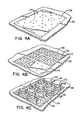
- the waterbed 10 includes a vinyl envelope 12 which encloses a plurality of cells 14, which are themselves constructed of vinyl or similar elastomeric material.
- An inlet valve 13 or other means is provided for filling the imperforate envelope 12.
- the cells 14 can be of any size, but in the preferred embodiment are approximately 23" x 25" x 8". Thus, nine cells placed close together in a 3 x 3 arrangement would approximate 72" x 84" x 8", which are the the dimensions of a "king-size" bed.
- the cell 14 includes metering apertures 16 in the pliant elastomeric material forming top surface 18 and bottom surface 20, enabling restricted fluid communication between the cells 14 in the envelope 12.
- the size and number of these metering apertures 16 can of course be varied to achieve the desired fluid flow characteristics to give the bed its desired resistance to wave motion.
- partition 22 Contained within each cell 14 is a partition 22 which separates the cell into at least an inner chamber 24 and an outer chamber 26.
- Partition 22 is preferably a vinyl loop connected between and bonded to the top surface 18 and bottom surface 20.
- the partition 22 can be configured in any number of patterns to control the relative size of chambers formed by the partition 22.
- partition 22 is shown as a closed loop in a four-arm star shape. Such a configuration results in the formation of a star-shaped inner chamber 24, and an outer chamber 26 that is effectively subdivided into four subchambers 26A, B, C and D. These subchambers are in limited fluid communication with one another by virtue of an orifice of restricted cross-section 28 that joins them, resulting from the proximity of the partition 22 to the cell side 30.
- the number of subchambers 26A-D can be varied from 1 (in the case where partition 22 forms a circle) to many (where partition 22 forms a complex, many-looped configuration).
- the benefit of this feature is that, by proper design, an essentially unlimited number of chambers, and, hence, restrictions to fluid flow, can be achieved.
- partition metering apertures 32 analogous to apertures 16, could be incorporated into partition 22 to adjust this flow.
- foam floatation piece 34 is incorporated into and proximate the top surface 18 of each cell.
- the foam floatation piece tends to keep the top surface 18 floating on top of the cell.
- Bottom surface 20, is preferably constructed of a vinyl material heavier than the rest of the cell 14, so that its more negative buoyancy tends to keep bottom surface 20 at the bottom of the cell.
- the bottom surface 20 is anchored to a base surface.
- FIG. 3 a cross-sectional view taken along line 3-3 of Figure 2 is shown. This view better illustrates the restricted cross-section 28 that is achieved between partition 22 and side 30. Fluid is metered between chambers through the cross-section 28.
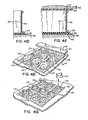
- Figure 4A shows a common cell top vinyl sheet 36 spread out on a base electrode 38 of a vinyl welding machine.
- Top vinyl sheet 36 is preferably the common top to the plurality of cells to be constructed.
- Metering apertures 16 are also shown.
- Figure 4B illustrates the pre-scored foam floatation pieces 32 as placed on top sheet 36 and registered with metering apertures 16.
- Figure 4C illustrates the placement of vinyl-wrapped internal chamber dies 40.
- Dies 40 are typically made of aluminum, brass or other metal, and can be shaped in any manner, to achieve the desired partition shape discussed hereinabove.
- the material for partition 22 is wrapped on the inside of die 40 and draped over its top and bottom edges. This places the vinyl of partition 22 in contact with the vinyl of top sheet 36, as is more clearly shown in Figure 4D, a cross-sectional view taken along line 4D-4D of Figure 4C.
- Figure 4E illustrates the placement of the individual cell bottom vinyl sheets 20 on the vinyl-wrapped internal chamber dies 40.
- the top electrode 42 of the vinyl welding machine is then placed over the cells in preparation for the first weld to be made.
- Figure 4F is a cross-sectional view taken along line 4F-4F of Figure 4E showing the making of the internal chamber weld.
- bottom vinyl sheet 20 will be welded at 44 to partition 22
- top vinyl sheet 36 will be welded at 46 to partition 22.
- Figure 4G shows the system after the first weld has been made and the top electrode removed.
- the welded bottom vinyl sheets 20 are, according to the invention, folded into the internal chamber dies 40 after the weld has been made to partition 22, and these dies 40 are then removed. It is important to note that the internal chamber dies 40 have an inwardly disposed margin forming a cavity. This method of weld formation enables the removal of the die after an internal chamber has been fully formed.
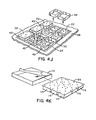
- Figure 4H illustrates the external chamber dies 48 with the material for the cell sides 30 wrapped around the inner margins of the external dies 48, which also have an inwardly disposed margin forming a cavity.
- Bottom vinyl sheets 20 are spread out over the perimeter of external chamber dies 48. The vinyl sheets 20 may be held in place with masking tape.
- Top electrode 42 is again placed over the cells, in preparation for the formation of the second weld seal.
- Figure 41 is a cross-sectional view taken along line 41-41 of Figure 4H showing the formation of the external chamber weld.
- bottom vinyl sheet 20 will be welded at region 50 to cell side 30, and top vinyl sheet 36 will be welded at region 52 to cell side 30.
- Figure 4J shows the system after this second weld has been made and the top electrode 42 ( Figure 41) removed.
- the welded bottom sheets 20 are folded within the external chamber dies 48 and then dies 48 are removed.
- two cells have been formed with one internal to the other in a manner adapted to large-scale mass production with minimal rearrangement of the pliant material forming the waterbed bladder.
- Figure 4K illustrates"the completed cell array 54 as inverted and placed within the vinyl envelope 12. Then only is the envelope 12 sealed in a standard manner to complete the waterbed.
Landscapes
- Chemical & Material Sciences (AREA)
- Dispersion Chemistry (AREA)
- Health & Medical Sciences (AREA)
- General Health & Medical Sciences (AREA)
- Nursing (AREA)
- Mattresses And Other Support Structures For Chairs And Beds (AREA)
- Buffer Packaging (AREA)
Applications Claiming Priority (2)
| Application Number | Priority Date | Filing Date | Title |
|---|---|---|---|
| US567466 | 1984-01-03 | ||
| US06/567,466 US4574026A (en) | 1984-01-03 | 1984-01-03 | Damped waterbed mattress and method for manufacturing same |
Publications (2)
| Publication Number | Publication Date |
|---|---|
| EP0147497A2 true EP0147497A2 (fr) | 1985-07-10 |
| EP0147497A3 EP0147497A3 (fr) | 1986-06-11 |
Family
ID=24267276
Family Applications (1)
| Application Number | Title | Priority Date | Filing Date |
|---|---|---|---|
| EP84101869A Withdrawn EP0147497A3 (fr) | 1984-01-03 | 1984-02-22 | Lit à matelas d'eau amorti et son procédé de fabrication |
Country Status (4)
| Country | Link |
|---|---|
| US (1) | US4574026A (fr) |
| EP (1) | EP0147497A3 (fr) |
| KR (1) | KR850005257A (fr) |
| CA (1) | CA1218170A (fr) |
Cited By (1)
| Publication number | Priority date | Publication date | Assignee | Title |
|---|---|---|---|---|
| WO1994001024A1 (fr) * | 1992-07-01 | 1994-01-20 | Martin Baumgartner | Lit a elements similaires a des lattes formant la surface de repos et a corps tubulaire de support des elements similaires a des lattes |
Families Citing this family (8)
| Publication number | Priority date | Publication date | Assignee | Title |
|---|---|---|---|---|
| US4922563A (en) * | 1982-04-01 | 1990-05-08 | Advanced Sleep Products | Waterbed mattress with baffle chambers |
| JPS60217137A (ja) * | 1984-04-13 | 1985-10-30 | Kawasaki Heavy Ind Ltd | 多重壁構造のケ−スの製造方法 |
| US4715076A (en) * | 1985-10-17 | 1987-12-29 | Classic Corporation | Waterbed motion reduction and hydraulic enhancement system |
| US4960483A (en) * | 1989-06-26 | 1990-10-02 | Switlik Parachute Company, Inc. | Heat pressing apparatus for making an inflatable life vest and method for use thereof |
| US5172437A (en) * | 1989-08-18 | 1992-12-22 | Strata Flotation, Inc. | Waterbed mattress with hexagonal baffle structure, and method and apparatus for manufacturing the same |
| US5060328A (en) * | 1990-10-09 | 1991-10-29 | Larson Lynn D | Waterbed mattress with spring insert |
| DE4413445C2 (de) * | 1994-04-18 | 1996-02-01 | Josef Graf | Verfahren zum Herstellen einer Luftmatratze mit einem als Pumpe wirkenden Teil und einem durch die Pumpe aufzupumpenden Teil |
| JP2000500675A (ja) * | 1995-11-13 | 2000-01-25 | サンライズ メディカル シーシージー インコーポレイテッド | セル形エアロスマットレスシステム |
Family Cites Families (5)
| Publication number | Priority date | Publication date | Assignee | Title |
|---|---|---|---|---|
| US4204289A (en) * | 1978-04-14 | 1980-05-27 | Classic Corporation | Waterbed mattress |
| US4229929A (en) * | 1978-06-05 | 1980-10-28 | Leslie Vajtay | Thermoplastic container |
| US4345348A (en) * | 1978-10-10 | 1982-08-24 | Monterey Manufacturing, Inc. | Waterbed mattress with a baffle |
| US4325152A (en) * | 1979-02-28 | 1982-04-20 | Michael Carpenter | Flotation mattress |
| US4475257A (en) * | 1982-01-26 | 1984-10-09 | Phillips Raymond M | Wave motion absorber for water bed mattresses |
-
1984
- 1984-01-03 US US06/567,466 patent/US4574026A/en not_active Expired - Lifetime
- 1984-02-22 EP EP84101869A patent/EP0147497A3/fr not_active Withdrawn
- 1984-04-30 KR KR1019840002312A patent/KR850005257A/ko not_active Withdrawn
- 1984-07-16 CA CA000458961A patent/CA1218170A/fr not_active Expired
Cited By (1)
| Publication number | Priority date | Publication date | Assignee | Title |
|---|---|---|---|---|
| WO1994001024A1 (fr) * | 1992-07-01 | 1994-01-20 | Martin Baumgartner | Lit a elements similaires a des lattes formant la surface de repos et a corps tubulaire de support des elements similaires a des lattes |
Also Published As
| Publication number | Publication date |
|---|---|
| EP0147497A3 (fr) | 1986-06-11 |
| KR850005257A (ko) | 1985-08-24 |
| CA1218170A (fr) | 1987-02-17 |
| US4574026A (en) | 1986-03-04 |
Similar Documents
| Publication | Publication Date | Title |
|---|---|---|
| US4627121A (en) | Damped waterbed mattress and method for manufacturing same | |
| US4964183A (en) | Tanning tub | |
| US4574026A (en) | Damped waterbed mattress and method for manufacturing same | |
| US4942634A (en) | Damped fluid displacement support system and method for making the same | |
| US5231718A (en) | Combined cellular material and innerspring support system | |
| US4168555A (en) | Water mattress with dampening construction | |
| US20020108179A1 (en) | Water-filled seat cushion | |
| US20030200610A1 (en) | Inflatable bed | |
| US4310936A (en) | Water mattress with internal damping means | |
| US4912789A (en) | Waterbed mattress | |
| US4245361A (en) | Water bed mattress | |
| US4420356A (en) | Flotation mattress and method | |
| US4577356A (en) | Waterbed mattress with baffle chambers | |
| US4241465A (en) | Waveless waterbed mattress | |
| US4370768A (en) | Damped fluid displacement support system | |
| US4079473A (en) | Water bed mattress having a fluid support member | |
| CA2057563C (fr) | Systeme de soutien a deplacement d'air amorti | |
| US5566408A (en) | Suspended coil wave reduction system for a water mattress | |
| US4858263A (en) | Cellular waterbed component and bed containing same | |
| CA2156684A1 (fr) | Lit d'eau a cellules d'air communicantes | |
| US4187569A (en) | Water mattress construction | |
| US5669091A (en) | Structure of water bed | |
| US6553591B1 (en) | Fluid-containing body support air cushion | |
| US4750959A (en) | Waterbed mattress with baffle chambers | |
| US5010607A (en) | Damping chamber for waterbed mattress |
Legal Events
| Date | Code | Title | Description |
|---|---|---|---|
| PUAI | Public reference made under article 153(3) epc to a published international application that has entered the european phase |
Free format text: ORIGINAL CODE: 0009012 |
|
| AK | Designated contracting states |
Designated state(s): DE FR GB |
|
| PUAL | Search report despatched |
Free format text: ORIGINAL CODE: 0009013 |
|
| AK | Designated contracting states |
Kind code of ref document: A3 Designated state(s): DE FR GB |
|
| STAA | Information on the status of an ep patent application or granted ep patent |
Free format text: STATUS: THE APPLICATION IS DEEMED TO BE WITHDRAWN |
|
| 18D | Application deemed to be withdrawn |
Effective date: 19860829 |
|
| RIN1 | Information on inventor provided before grant (corrected) |
Inventor name: WINTHER, HOWARD A. |