EP0147521B1 - Verfahren zur Regelung von Verbrennungsprozessen - Google Patents
Verfahren zur Regelung von Verbrennungsprozessen Download PDFInfo
- Publication number
- EP0147521B1 EP0147521B1 EP84109594A EP84109594A EP0147521B1 EP 0147521 B1 EP0147521 B1 EP 0147521B1 EP 84109594 A EP84109594 A EP 84109594A EP 84109594 A EP84109594 A EP 84109594A EP 0147521 B1 EP0147521 B1 EP 0147521B1
- Authority
- EP
- European Patent Office
- Prior art keywords
- ultraviolet lamp
- waste gas
- irradiation
- flow
- photoelectrically
- Prior art date
- Legal status (The legal status is an assumption and is not a legal conclusion. Google has not performed a legal analysis and makes no representation as to the accuracy of the status listed.)
- Expired - Lifetime
Links
Images
Classifications
-
- F—MECHANICAL ENGINEERING; LIGHTING; HEATING; WEAPONS; BLASTING
- F23—COMBUSTION APPARATUS; COMBUSTION PROCESSES
- F23N—REGULATING OR CONTROLLING COMBUSTION
- F23N5/00—Systems for controlling combustion
- F23N5/003—Systems for controlling combustion using detectors sensitive to combustion gas properties
- F23N5/006—Systems for controlling combustion using detectors sensitive to combustion gas properties the detector being sensitive to oxygen
-
- G—PHYSICS
- G01—MEASURING; TESTING
- G01N—INVESTIGATING OR ANALYSING MATERIALS BY DETERMINING THEIR CHEMICAL OR PHYSICAL PROPERTIES
- G01N27/00—Investigating or analysing materials by the use of electric, electrochemical, or magnetic means
- G01N27/62—Investigating or analysing materials by the use of electric, electrochemical, or magnetic means by investigating the ionisation of gases, e.g. aerosols; by investigating electric discharges, e.g. emission of cathode
- G01N27/64—Investigating or analysing materials by the use of electric, electrochemical, or magnetic means by investigating the ionisation of gases, e.g. aerosols; by investigating electric discharges, e.g. emission of cathode using wave or particle radiation to ionise a gas, e.g. in an ionisation chamber
- G01N27/66—Investigating or analysing materials by the use of electric, electrochemical, or magnetic means by investigating the ionisation of gases, e.g. aerosols; by investigating electric discharges, e.g. emission of cathode using wave or particle radiation to ionise a gas, e.g. in an ionisation chamber and measuring current or voltage
Definitions
- the present invention relates to a method for controlling combustion processes according to the preamble of claim 1.
- Wood, coal, natural gas, petroleum and other organic substances are burned on a large scale in private and commercial combustion plants and heat engines. If too much air or oxygen is added to the combustion, a loss occurs because the excess amount of air dissipates heat. If too little air is supplied, carbon black oxide and also hydrocarbons are formed in addition to soot, among them some highly carcinogenic species, such as the benzopyrene.
- the increasing pollution of the air with carcinogenic substances poses a very serious threat to the public. To avoid the explosion risk associated with the formation of these pollutants, heating systems and automobiles in particular must always be operated with a certain excess of air without catalytic afterburning. On the other hand, one does not want to waste the valuable fuels unnecessarily due to an excess of air.
- the air ratio ⁇ can be regulated automatically, for example with a zirconium oxide oxygen probe.
- the disadvantages of the zirconium oxide oxygen probe are that its function is impaired by lead and other substances that may be contained in the exhaust gas and can therefore only be used with certain fuels.
- An electrode exposed to the exhaust gas must be protected with porous ceramic; there is a risk of pollution.
- the diffusion of 0 2 through the ceramic is relatively slow, especially at low temperatures, so that the regulating cycle is also correspondingly slow.
- a method of the type mentioned is known from US-A-3 881 111.
- the known method serves for the detection of nitrogen oxide in the combustion exhaust gas.
- an ultraviolet light source is used, which delivers ultraviolet light in the wavelength range between 1.2 and 1.3 ⁇ .
- a shell-like growth of the finest suspended particles of the exhaust gas is proposed as a possible mechanism for the formation of very fine particles with a low photoelectric work function.
- the low volatility coal or. Ash core of the particles in the hot zones of combustion.
- the hydrocarbon condensates either lower the photoelectric work function of the particles or themselves have a low ionization potential, so that the agglomerate is electrically charged when irradiated with ultraviolet light and is therefore able to generate a corresponding signal in a detector.
- particles that are already electrically charged in the combustion process can likewise be eliminated in a known, electrical pre-filter before the photoelectric charging.
- the positive and negative charge carriers generated by photoelectric charge separation can also be sorted according to their size and fed to a sensor, so that only a certain charge or size class or a section of the size spectrum is detected by the sensor.
- the sorting can take place with the aid of inertial forces in a diffusion path and / or by means of an electrical direct or alternating field.
- the relative or absolute amount of the charge carriers generated and / or the relative or absolute size of the current generated by these charge carriers can be changed depending on the combustion process and / or fuel.
- the intensity and / or the duration of the action of the ultraviolet light on the exhaust gas can also be changed.
- the speed and / or the volume of the exhaust gas component exposed to the ultraviolet light can be changed.
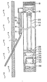
- the arrangement shown in FIG. 1 is particularly suitable for regulating the air ratio ⁇ in a heating system operated with oil.
- Exhaust gas is removed from the chimney 2 via the intake pipe 4.
- the intake pipe 4 is long enough, in accordance with the selected intake speed, that the exhaust gases practically cool down to ambient temperature after exiting the chimney 2.
- the suction pipe 4 is also not set up horizontally, so that any condensates can drip back into the chimney 2.
- the filter 6 retains coarse particles.
- a metallic cylinder 10 is kept electrically insulated concentrically. If an electrical direct voltage is applied to the cylinder 10 opposite the pipe 8 via the bushing 12, an electrical field is created which is perpendicular to the flow of the exhaust gas and filters the charged particles out of the exhaust gas stream.
- the exhaust gas stream pretreated in this way now passes through the holes 16, which are annularly distributed on the outer edge of a larger pipe 14, to a stream of cleaned outside air. The outside air is cleaned by suction through the filter 18.
- the light source 20 is a commercially available low-pressure mercury lamp which essentially delivers ultraviolet light with an energy of 4.9 eV.
- the light source 20 is surrounded by a conductive network 22 to shield electrical interference fields. Because of the laminar flow, the particle-carrying exhaust gas stream running on the outer edge of the tube 14 cannot contaminate the lamp.
- the ultraviolet light now emits photoelectrons from the particles if their work function is below 4.9 eV. Due to the alternating voltage applied between 22 and 14, these electrons or the negative small ions possibly formed from them hit electrodes 22 or 14 and are thus removed from the gas stream by absorption or neutralization. However, the amplitude and frequency of the alternating voltage is selected such that the positively charged particles which remain are only trembling due to their low electrical mobility compared to the electrons or the small ions formed from them, and therefore their majority remain in the current.
- the suspended particles are now led out of the ionization path by the gas stream via the holes 24 and 26.
- the holes 24 and 26 distributed in a ring on the circumference of the lamp holder 28 on hole circles of different diameters are also offset from each other so that the light cannot exit the ionization path.
- the air containing particles now flows through an electrical shielding grid 30 through a filter 34 held on an insulator 32, which traps all particles. If some particles carry a positive charge, a positive electric charge or a positive electric current can be tapped at the electrode 36, which after appropriate amplification serves for the continuous or point-by-point automatic or manual regulation of the air ratio ⁇ .
- the blower 38 generates both the flow of the outside air cleaned by the filter 18 and the exhaust gas flow through the intake pipe 4.
- the length and diameter of the intake pipe 4 decisively determine the mixture ratio of exhaust gas / outside air.
- the partial flow of the exhaust gas and / or the intensity and / or the length of the low-pressure mercury discharge 20 and the diameter of the tube 14 are selected so that the signal on charged particles is sufficiently large, ie measured reliably and further evaluated in a control circuit known per se can to regulate the air ratio ⁇ .
Landscapes
- Engineering & Computer Science (AREA)
- Chemical & Material Sciences (AREA)
- Health & Medical Sciences (AREA)
- Biochemistry (AREA)
- General Physics & Mathematics (AREA)
- Mechanical Engineering (AREA)
- Toxicology (AREA)
- Chemical Kinetics & Catalysis (AREA)
- Electrochemistry (AREA)
- Physics & Mathematics (AREA)
- Life Sciences & Earth Sciences (AREA)
- Analytical Chemistry (AREA)
- Combustion & Propulsion (AREA)
- General Health & Medical Sciences (AREA)
- General Engineering & Computer Science (AREA)
- Immunology (AREA)
- Pathology (AREA)
- Regulation And Control Of Combustion (AREA)
- Air Supply (AREA)
- Electrical Control Of Air Or Fuel Supplied To Internal-Combustion Engine (AREA)
- Physical Or Chemical Processes And Apparatus (AREA)
- Exhaust Gas After Treatment (AREA)
- Investigating Or Analysing Materials By Optical Means (AREA)
- Control Of Steam Boilers And Waste-Gas Boilers (AREA)
- Treating Waste Gases (AREA)
- Electrostatic Separation (AREA)
Description
- Die vorliegende Erfindung betrifft ein Verfahren zur Regelung von Verbrennungsprozessen gemäß dem Oberbegriff des Anspruchs 1.
- Holz, Kohle, Erdgas, Erdöl und andere organische Stoffe werden in privaten und gewerblichen Feuerungsanlagen und Wärmekraftmaschinen in grossem Massstab verbrannt. Führt man der Verbrennung zuviel Luft oder Sauerstoff zu, so tritt ein Verlust auf, weil die überschüssige Luftmenge Wärme abführt. Führt man zu wenig Luft zu, so bildet sich neben Russ das giftige Kohlenmonoxyd und ausserdem Kohlenwasserstoffe, unter diesen einige hochkarzinogene Arten, wie z.B. das Benzpyren. Die zunehmende Verunreinigung der Luft mit karzinogenen Stoffen stellt eine sehr ernsthafte Bedrohung der Öffentlichkeit dar. Zur Vermeidung der mit der Bildung dieser Schadstoffe ausserdem verbundenen Explosionsgefahr müssen insbesondere Heizungsanlagen und Automobile ohne katalytische Nachverbrennung stets mit einem gewissen Luftüberschuss betrieben werden. Auf der anderen Seite will man aber die kostbaren Brennstoffe durch einen zu grossen Luftüberschuss nicht unnötig verschwenden.
- Es ist schon lange bekannt, dass das Brennstoff-Luftverhältnis λ für den Ablauf der Verbrennung wesentlich ist. Der Wirkungsgrad und die Schadstoffemission von Verbrennungsmotoren und Feuerungsanlagen ist durch λ bestimmt. Genau ist A durch das Verhältnis

- Es ist weiterhin bekannt, dass man z.B. mit einer Zirkonoxid-Sauerstoffsonde die Luftzahl λ automatisch regulieren kann. Damit wurden z.B. bei Heizungsanlagen 5-10% Brennstoff eingespart und zugleich die Abgaswerte deutlich verbessert. Die Nachteile der Zirkonoxid-Sauerstoffsonde bestehen darin, dass sie durch Blei und andere möglicherweise im Abgas enthaltenen Stoffe in ihrer Funktion beeinträchtigt wird und damit nur mit bestimmten Brennmaterialien verwendet werden kann. Eine dem Abgas ausgesetzte Elektrode muss mit poröser Keramik geschützt werden; es tritt die Gefahr der Verschmutzung auf. Weiterhin ist die Diffusion des 02 durch die Keramik besonders bei niedrigen Temperaturen relativ langsam, so dass der Regulierzyklus ebenfalls entsprechend langsam ist. Dazu kommt noch, dass ein temperaturunabhängiges Schaltsignal nur bei der Luftzahl λ = 1 auftritt. Für Verbrennungsanlagen und Kraftfahrzeuge ohne katalytische Nachverbrennung muss daher durch Zutitrieren von H2 der beim optimalen A vorhandene überschüssige Sauerstoff zuerst entfernt werden, bevor das Abgas der Festelektrolytsonde zugeführt wird. Dies bedingt einen relativ komplexen und entsprechend kostspieligen Mechanismus, der bisher nur in grossen Verbrennungsanlagen eingesetzt werden konnte.
- Ein Verfahren der eingangs genannten Art ist aus der US-A-3 881 111 bekannt. Das bekannte Verfahren dient zum Nachweis von Stickoxid im Verbrennungs-Abgas. Entsprechend dem lonisierungspotential) von Stickoxid von 9,25 eV wird eine Ultraviolett-Lichtquelle verwendet, welche ultraviolettes Licht im Wellenlängenbereich zwischen 1,2 und 1,3 Ä liefert.
- Aus einem Artikel von Burtscher et al in Journal of Applied Physics, Band 53, Nr. 5, Mai 1982, Seiten 3787-3791, New York, USA ist die photoemmissive Aufladung von Aerosolpartikeln durch UV-Strahlung entsprechend einer Photoenergie von 4,9 eV zur Feststellung von Partikelgrösse und Partikeldichte in Aerosol bekannt.
- Es ist die Aufgabe der vorliegenden Erfindung, ein einfaches und zuverlässiges Verfahren zur Regelung von Verbrennungs-prozessen vorzuschlagen, wobei als Grundlage die Regulierung der Luftzahl λ dient. Erfindungsgemäss wird diese Aufgabe durch ein Verfahren mit den Merkmalen des Patentanspruchs 1 gelöst. Generell wird von der Erkenntnis ausgegangen, dass bei ungenügender Luftzufuhr nicht ganz verbrannte, d.h. oxidierbare Substanzen oder Radikale im Abgas auftreten. Solche Substanzen haben bekanntlich die Tendenz, Elektronen abzugeben, d.h. die lonisierungs- oder Austrittsarbeit für Elektronen ist relativ gering. Zum Nachweis dieser Substanzen bzw. Radikale wird von der bekannten elektrischen Aufladung der Schwebeteilchen mittels Photoemission von Elektronen Gebrauch gemacht, wie es grundsätzlich in den Publikationen "Atmospheric Environment, Vol. 17, No. 3, pp. 665―657, 1983" und "J. Appl. Phys. 53(51, May 1982, pp. 3787-3791" beschrieben ist. Mit Hilfe der photoelektrischen Aufladung lassen sich nämlich allerfeinste, optisch noch nicht feststellbare Schwebeteilchen mit niedriger photoelektrischer Austrittsarbeit effizient und selektiv, d.h. auch in Anwesenheit anderer Partikel und Materialien, nachweisen. Das Auftreten der genannten Partikel im Abgas einer Verbrennung ist dann ein Signal für Sauerstoffmangel und kann somit zur Regulierung der Luftzahl λ dienen.
- Als möglicher Mechanismus für die Entstehung feinster Teilchen mit niedriger photoelektrischer Austrittsarbeit wird ein schalenartiges Wachstum der feinsten Schwebeteilchen des Abgases vorgeschlagen. Demnach bildet sich zuerst der schwerflüchtige Kohle-bzw. Aschkern der Teilchen in den heissen Zonen der Verbrennung. Beim Abwandem in die kälteren Zonen kondensieren auf diesen Kernen die leichter flüchtigen Kohlenwasserstoffe und ihre Radikale, falls sie wegen ungenügender Luftzfuhr vorhanden sind. Die Kohlenwasserstoffkondensate erniedrigen nun entweder die photoelektrische Austrittsarbeit der Teilchen oder besitzen selbst ein niedriges lonisierungspotential, so dass das Agglomerat bei Bestrahlen mit ultraviolettem Licht elektrisch aufgeladen wird und damit in der Lage ist, in einem Detektor ein entsprechendes Signal zu erzeugen. Es ist wichtig zu bemerken, dass besonders die weniger stabilen und damit besonders giftigen Kohlenwasserstoffe und ihre Fragmente leicht Elektronen abgeben und damit effektiv und mit unerhört hoher Empfindlichkeit nachgewiesen werden können. Unter Umständen muss nur ein Bruchteil der Oberfläche eines ultrafeinen, noch nicht sichtbaren Teilchens mit einer einatomigen Schicht der genannten instabilen Kohlenwasserstoffe bedeckt sein, damit die photoelektrische Aufladung eintreten kann.
- Weiterhin wurde beobachtet, dass mindestens einige Teilchen mit niedriger photoelektrischer Austrittsarbeit beim Abkühlen der Abgase unter den Taupunkt überleben. Es ist also möglich, die photoelektrische Aufladung der Teilchen erst nach dem Abkühlen der Abgase und nach dem Ausscheiden flüssiger oder nebelförmiger Kondensate durchzuführen. Grössere Abgasteilchen ab etwa 1 um Durchmesser lassen sich wegen Rückdiffusion der Photoelektronen sowieso kaum aufladen und können daher zur Vermeidung der Verschmutzung einer Sonde ohne weiteres vor der photoelektrischen Aufladung durch ein gröberes Filter aussortiert weren.
- In der Verbrennung bereits elektrisch aufgeladene Teilchen können zur Vermeidung eines Hintergrundsignals ebenfalls vor der photoelektrischen Aufladung in einem bekannten, elektrischen Vorfilter ausgeschieden werden.
- Die durch lichtelektrische Ladungstrennung erzeugten, positiven und negativen Ladungsträger können auch nach ihrer Grösse sortiert und einem Messwertaufnehmer zugeführt werden, so dass nur eine bestimmte Ladungs- oder Grössenklasse bzw. ein Auschnitt aus dem Grössenspektrum vom Messwertaufnehmer erfasst wird.
- Die Sortierung kann mit Hilfe von Trägheitskraften in einer Diffusionsstrecke und/oder mittels eines elektrischen Gleichoder Wechselfeldes erfolgen.
- Die als Messwertgrösse herangezogene, relative oder absolute Menge der erzeugten Ladungsträger und/oder die relative oder absolute Grösse des durch diese Ladungsträger erzeugten Stromes kann in Abhängigkeit vom Verbrennungsvorgang und/oder Brennstoff verändert werden.
- Andererseits kann auch die Intensität und/oder die Zeitdauer der Einwirkung des ultravioletten Lichtes auf das Abgas verändert werden.
- Schliesslich kann die Geschwindigkeit und/oder das Volumen des dem ultravioletten Licht ausgesetzten Abgasanteils verändert werden.
- Im folgenden wird ein Ausführungsbeispiel des erfindungsgemässen Verfahrens näher erläutert, wobei auf die beiliegende Zeichnung Bezug genommen wird, in der eine beispielsweise Darstellung einer Anordnung zur Durchführung des erfindungsgemäsen Verfahrens in einem schematischen Längsschnitt gezeigt ist.
- Die in Fig. 1 gezeigte Anordnung ist vor allem zur Regelung der Luftzahl λ in einer mit Oel betriebenen Heizungsanlage geeignet.
- Abgas wird über das Ansaugrohr 4 aus dem Kamin 2 entnommen. Das Ansaugrohr 4 ist entsprechend der gewählten Ansauggeschwindigkeit so lang, dass die Abgase nach Austritt aus dem Kamin 2 praktisch auf Umgebungstemperatur abkühlen. Das Ansaugrohr 4 ist auch nicht horizontal aufgestellt, so dass eventuelle Kondensate wieder in den Kamin 2 zurücktropfen können. Das Filter 6 hält grobe Teilchen zurück. Im darauf folgenden Rohr 8 wird konzentrisch ein metallischer Zylinder 10 elektrisch isoliert gehalten. Legt man über die Durchführung 12 eine elektrische Gleichspannung an den Zylinder 10 gegenüber dem Rohr 8, so entsteht ein zur Strömung des Abgases senkrechtes elektrisches Feld, das die geladenen Teilchen aus dem Abgasstrom herausfiltert. Der so vorbehandelte Abgasstrom tritt nun über die am äusseren Rand eines grösseren Rohres 14 ringförmig verteilten Löcher 16 zu einem Strom gereinigter Aussenluft. Die Aussenluft wird durch Ansaugen über das Filter 18 gereinigt.
- Abgas und gereinigte Aussenluft strömen nun laminar durch das Rohr 14, in dessen Mitte konzentrisch die Lichtquelle 20 montiert ist. Die Lichtquelle 20 ist eine handelsübliche Quecksilberniederdrucklampe, welche im wesentlichen ultraviolettes Licht der Energie 4.9 eV liefert. Die Lichtquelle 20 ist zur Abschirmung elektrischer Störfelder mit einem leitenden Netz 22 umgeben. Wegen der laminaren Strömung kann der am äusseren Rand des Rohres 14 verlaufende, teilchentragende Abgasstrom die Lampe nicht verschmutzen. Durch das ultraviolette Licht werden nun aus den Teilchen Photoelektronen emittiert, falls ihre Austrittsarbeit unterhalb 4.9 eV liegt. Auf Grund der zwischen 22 und 14 angelegten Wechselspannung stossen diese Elektronen bzw. die aus ihnen eventuell gebildeten negativen Kleinionen auf die Elektroden 22 oder 14 und werden so durch Absorption bzw. Neutralisation aus dem Gasstrom entfernt. Amplitude und Frequenz der Wechselspannung ist aber so gewählt, dass die zurückbleibenden positiv geladenen Teilchen auf Grund ihrer im Vergleich zu den Elektronen bzw. den aus ihnen gebildeten Kleinionen geringen elektrischen Beweglichkeit nur eine Zitterbewegung sehr kleiner Amplitude ausführen und daher ihre Mehrzahl im Strom verbleibt.
- Die Schwebeteilchen werden nun vom Gasstrom über die Löcher 24 und 26 aus der lonisierungsstrecke herausgeführt. Die ringförmig auf dem Umfang der Lampenhalterung 28 auf Lochkreisen unterschiedlichen Durchmessers verteilten Löcher 24 und 26 sind ausserdem gegeneinander versetzt, so dass das Licht nicht aus der lonisierungsstrecke austreten kann. Die teilchenhaltige Luft strömt nun über ein elektrisches Abschirmgitter 30 durch ein auf einem Isolator 32 gehaltenes Filter 34, welches alle Teilchen auffängt. Falls einige Teilchen eine positive Ladung tragen, kann an der Elektrode 36 eine positive elektrische Ladung oder ein positiver elektrischer Strom abgegriffen werden, welcher nach entsprechender Verstärkung zur kontinuierlichen oder punktweisen automatischen oder manuellen Regulierung der Luftzahl λ dient. Das Gebläse 38 erzeugt einerseits sowohl den Strom der durch das Filter 18 gereinigten Aussenluft, als auch den Abgasstrom durch das Ansaugrohr 4. Es ist wiederum durch das Netz 40 vom Filterraum elektrisch getrennt. Länge und Durchmesser des Ansaugrohres 4 bestimmen massgeblich das Mischungverhältnis Abgas/ Aussenluft. Der Teilstrom des Abgases und/oder die Intensität und/oder die Länge der Quecksilberniederdruckentladung 20 sowie der Durchmesser des Rohres 14 werden so gewählt, dass das Signal an geladenen Teilchen ausreichend gross ist, d.h. zuverlässig gemessen und in einem an sich bekannten Regelkreis weiter ausgewertet werden kann, um die Luftzahl λ zu regulieren.
- Es versteht, sich das durch entsprechende Umgestaltung der hier beschriebenen Anordnung weitere Anwendungsgebiete für das erfindungsgemässe Verfahren erschlossen werden können, z.B. auf dem Gebiet von Fahrzeugmotoren oder anderer Wärmekraftmaschinen.
Claims (11)
Priority Applications (1)
| Application Number | Priority Date | Filing Date | Title |
|---|---|---|---|
| AT84109594T ATE55179T1 (de) | 1983-08-24 | 1984-08-11 | Verfahren zur regelung von verbrennungsprozessen. |
Applications Claiming Priority (2)
| Application Number | Priority Date | Filing Date | Title |
|---|---|---|---|
| DE3330509 | 1983-08-24 | ||
| DE3330509A DE3330509C1 (de) | 1983-08-24 | 1983-08-24 | Verfahren zur Regelung von Verbrennungsprozessen |
Publications (2)
| Publication Number | Publication Date |
|---|---|
| EP0147521A1 EP0147521A1 (de) | 1985-07-10 |
| EP0147521B1 true EP0147521B1 (de) | 1990-08-01 |
Family
ID=6207311
Family Applications (1)
| Application Number | Title | Priority Date | Filing Date |
|---|---|---|---|
| EP84109594A Expired - Lifetime EP0147521B1 (de) | 1983-08-24 | 1984-08-11 | Verfahren zur Regelung von Verbrennungsprozessen |
Country Status (6)
| Country | Link |
|---|---|
| US (1) | US4959010A (de) |
| EP (1) | EP0147521B1 (de) |
| JP (1) | JPH0765738B2 (de) |
| AT (1) | ATE55179T1 (de) |
| CA (1) | CA1229745A (de) |
| DE (2) | DE3330509C1 (de) |
Families Citing this family (17)
| Publication number | Priority date | Publication date | Assignee | Title |
|---|---|---|---|---|
| DE3417525C1 (de) * | 1984-05-11 | 1986-01-09 | Matter + Siegmann Ag, Wohlen | Vorrichtung zur quantitativen und qualitativen Erfassung von kohlenwasserstoffhaltigen Schwebeteilchen in Gasen |
| CH680238A5 (de) * | 1989-12-04 | 1992-07-15 | Matter & Siegmann Ag | |
| IE922335A1 (en) * | 1991-07-19 | 1993-01-27 | Secr Defence Brit | Gas detection device and method |
| US5222887A (en) * | 1992-01-17 | 1993-06-29 | Gas Research Institute | Method and apparatus for fuel/air control of surface combustion burners |
| GB9306556D0 (en) * | 1993-03-30 | 1993-05-26 | Enviro Systems Ltd | Detector device |
| DE4321456C2 (de) * | 1993-06-29 | 1995-12-14 | Forschungszentrum Juelich Gmbh | Verfahren zur quantitativen Bestimmung von brennbaren Anteilen einer Probe und Vorrichtung zur Durchführung des Verfahrens |
| US5616172A (en) * | 1996-02-27 | 1997-04-01 | Nature's Quarters, Inc. | Air treatment system |
| US5997619A (en) * | 1997-09-04 | 1999-12-07 | Nq Environmental, Inc. | Air purification system |
| US7551964B2 (en) * | 2002-03-22 | 2009-06-23 | Leptos Biomedical, Inc. | Splanchnic nerve stimulation for treatment of obesity |
| FI118278B (fi) * | 2003-06-24 | 2007-09-14 | Dekati Oy | Menetelmä ja anturilaite hiukkaspäästöjen mittaamiseksi polttomoottorin pakokaasuista |
| EP1681550A1 (de) * | 2005-01-13 | 2006-07-19 | Matter Engineering AG | Verfahren und Vorrichtung zur Messung von Anzahlkonzentration und mittlerem Durchmesser von Aerosolpartikeln |
| US9433693B2 (en) | 2012-12-11 | 2016-09-06 | Aerobiotix, Inc. | Air-surface disinfection system, unit and method |
| US11938252B2 (en) | 2012-12-11 | 2024-03-26 | Aerobiotix, Llc | Medical air handling system with laminar flow and energy-based air decontamination |
| US9457119B2 (en) | 2012-12-11 | 2016-10-04 | Aerobiotix, Inc. | Fluid sterilization system |
| FI20135539A7 (fi) * | 2013-05-20 | 2014-11-21 | Valmet Technologies Oy | Terminen järjestelmä ja menetelmä termisen prosessin ohjaamiseksi |
| USD978313S1 (en) | 2020-05-11 | 2023-02-14 | Aerobiotix, Llc | Air cleaner |
| US11629872B2 (en) | 2021-04-12 | 2023-04-18 | NQ Industries, Inc. | Single pass kill air purifier system and process of operation |
Family Cites Families (11)
| Publication number | Priority date | Publication date | Assignee | Title |
|---|---|---|---|---|
| US2005036A (en) * | 1932-02-03 | 1935-06-18 | Howe Alonzo H Don | Method and apparatus for gas analyses |
| US2950387A (en) * | 1957-08-16 | 1960-08-23 | Bell & Howell Co | Gas analysis |
| NL128781C (de) * | 1961-01-23 | |||
| US3178930A (en) * | 1963-04-08 | 1965-04-20 | Little Inc A | Monitor and spectrometer for atmospheric particulate matter |
| US3449667A (en) * | 1966-05-18 | 1969-06-10 | Gourdine Systems Inc | Electrogasdynamic method and apparatus for detecting the properties of particulate matter entrained in gases |
| DE2211720A1 (de) * | 1971-03-10 | 1972-11-02 | Waiden Research Corp., Cambridge, Mass. (V.St.A.) | Strahlungsionisationsdetektor |
| US3881111A (en) * | 1973-09-27 | 1975-04-29 | California Inst Of Techn | Method and apparatus for the detection of nitric oxide |
| US3997416A (en) * | 1974-09-20 | 1976-12-14 | Exxon Research And Engineering Company | Method and apparatus for analyzing gaseous mixtures |
| US4509912A (en) * | 1975-12-16 | 1985-04-09 | Vanberkum Robert A | Combustion efficiency improving apparatus |
| CH649231A5 (de) * | 1980-10-28 | 1985-05-15 | Hans Christoph Siegmann Prof D | Verfahren zum elektrischen aufladen von schwebeteilchen in gasen. |
| US4377749A (en) * | 1981-02-25 | 1983-03-22 | Young Robert A | Photoionizer |
-
1983
- 1983-08-24 DE DE3330509A patent/DE3330509C1/de not_active Expired
-
1984
- 1984-08-11 AT AT84109594T patent/ATE55179T1/de active
- 1984-08-11 DE DE8484109594T patent/DE3482872D1/de not_active Expired - Fee Related
- 1984-08-11 EP EP84109594A patent/EP0147521B1/de not_active Expired - Lifetime
- 1984-08-20 US US06/642,346 patent/US4959010A/en not_active Expired - Fee Related
- 1984-08-20 CA CA000461369A patent/CA1229745A/en not_active Expired
- 1984-08-24 JP JP59177361A patent/JPH0765738B2/ja not_active Expired - Lifetime
Also Published As
| Publication number | Publication date |
|---|---|
| CA1229745A (en) | 1987-12-01 |
| JPS6089622A (ja) | 1985-05-20 |
| EP0147521A1 (de) | 1985-07-10 |
| US4959010A (en) | 1990-09-25 |
| JPH0765738B2 (ja) | 1995-07-19 |
| DE3482872D1 (de) | 1990-09-06 |
| ATE55179T1 (de) | 1990-08-15 |
| DE3330509C1 (de) | 1985-05-23 |
Similar Documents
| Publication | Publication Date | Title |
|---|---|---|
| EP0147521B1 (de) | Verfahren zur Regelung von Verbrennungsprozessen | |
| DE3417525C1 (de) | Vorrichtung zur quantitativen und qualitativen Erfassung von kohlenwasserstoffhaltigen Schwebeteilchen in Gasen | |
| Wang et al. | Characterization of organic aerosol produced during pulverized coal combustion in a drop tube furnace | |
| DE3623939C2 (de) | ||
| ES2082655T3 (es) | Procedimiento y dispositivo de eliminacion de particulas del caudal de gas de escape de motores de combustion. | |
| DE69806002T2 (de) | Verfahren zur brennstoffherstellung | |
| DE4003564C2 (de) | Vorrichtung zur Verminderung kohlenstoffhaltiger partikelförmiger Materialien | |
| WO2016096521A1 (de) | Vorrichtung zur detektion von partikeln in einem abgas einer verbrennungsmaschine | |
| DE2229948A1 (de) | Messgeraet fuer phosphorverbindungen in luftatmosphaere | |
| DE2851477A1 (de) | Vorrichtung und verfahren zur erforschung von bodenschaetzen | |
| DE4038640A1 (de) | Vorrichtung zur ueberwachung von verbrennungsprozessen | |
| DE69424417T2 (de) | Verfahren zur versprühung von elektrolyten und deren chemischen analyse | |
| Vijayan et al. | Particle-induced X-ray emission (PIXE) analysis of coal fly ash | |
| DE4410090C1 (de) | Rauchmelder | |
| DE3625771C2 (de) | ||
| EP1681551B1 (de) | Verfahren und Vorrichtung zur Messung von Anzahlkonzentration und mittlerem Durchmesser von Aerosolpartikeln | |
| DE2739932A1 (de) | Ionisationsverfahren und teilchennachweisvorrichtung zur durchfuehrung des verfahrens | |
| Hunter et al. | Spark-induced breakdown spectroscopy: a description of an electrically generated LIBS-like process for elemental analysis of airborne particulates and solid samples | |
| DE2550881A1 (de) | Flammendetektor | |
| Kawada et al. | Feasibility study of copper ion migration from collected particles in corona discharge under several humidity conditions. | |
| Martens | Toward understanding the chemical composition of carbonaceous aerosols emitted by solid fuel burning | |
| Cereda et al. | Nuclear microscopy for the study of coal combustion related phenomena | |
| DE102016226263A1 (de) | Vorrichtung zur Detektion von Partikeln in einem Gas | |
| DE1542579A1 (de) | Verfahren und Einrichtungen zur Verbesserung der Wirkungsgrade von Oxydationsvorgaengen,insbesondere zum Entgiften der Abgase von Verbrennungsmotoren | |
| DE102009042113A1 (de) | Elektroabscheider und Verfahren zur Partikelabscheidung aus Gasen |
Legal Events
| Date | Code | Title | Description |
|---|---|---|---|
| PUAI | Public reference made under article 153(3) epc to a published international application that has entered the european phase |
Free format text: ORIGINAL CODE: 0009012 |
|
| AK | Designated contracting states |
Designated state(s): AT BE CH DE FR GB IT LI LU NL SE |
|
| 17P | Request for examination filed |
Effective date: 19850923 |
|
| 17Q | First examination report despatched |
Effective date: 19870521 |
|
| GRAA | (expected) grant |
Free format text: ORIGINAL CODE: 0009210 |
|
| AK | Designated contracting states |
Kind code of ref document: B1 Designated state(s): AT BE CH DE FR GB IT LI LU NL SE |
|
| PG25 | Lapsed in a contracting state [announced via postgrant information from national office to epo] |
Ref country code: IT Free format text: LAPSE BECAUSE OF FAILURE TO SUBMIT A TRANSLATION OF THE DESCRIPTION OR TO PAY THE FEE WITHIN THE PRESCRIBED TIME-LIMIT;WARNING: LAPSES OF ITALIAN PATENTS WITH EFFECTIVE DATE BEFORE 2007 MAY HAVE OCCURRED AT ANY TIME BEFORE 2007. THE CORRECT EFFECTIVE DATE MAY BE DIFFERENT FROM THE ONE RECORDED. Effective date: 19900801 |
|
| REF | Corresponds to: |
Ref document number: 55179 Country of ref document: AT Date of ref document: 19900815 Kind code of ref document: T |
|
| ITTA | It: last paid annual fee | ||
| REF | Corresponds to: |
Ref document number: 3482872 Country of ref document: DE Date of ref document: 19900906 |
|
| GBT | Gb: translation of ep patent filed (gb section 77(6)(a)/1977) | ||
| ET | Fr: translation filed | ||
| PLBE | No opposition filed within time limit |
Free format text: ORIGINAL CODE: 0009261 |
|
| STAA | Information on the status of an ep patent application or granted ep patent |
Free format text: STATUS: NO OPPOSITION FILED WITHIN TIME LIMIT |
|
| 26N | No opposition filed | ||
| EPTA | Lu: last paid annual fee | ||
| EAL | Se: european patent in force in sweden |
Ref document number: 84109594.6 |
|
| REG | Reference to a national code |
Ref country code: CH Ref legal event code: PLI Owner name: MATTER + SIEGMANN AG TRANSFER- ECOCHEM ANALYTICS, |
|
| REG | Reference to a national code |
Ref country code: GB Ref legal event code: 732E |
|
| NLUE | Nl: licence registered with regard to european patents |
Effective date: 19970117 |
|
| REG | Reference to a national code |
Ref country code: FR Ref legal event code: CL |
|
| PGFP | Annual fee paid to national office [announced via postgrant information from national office to epo] |
Ref country code: FR Payment date: 19980709 Year of fee payment: 15 |
|
| PGFP | Annual fee paid to national office [announced via postgrant information from national office to epo] |
Ref country code: AT Payment date: 19980714 Year of fee payment: 15 |
|
| PGFP | Annual fee paid to national office [announced via postgrant information from national office to epo] |
Ref country code: SE Payment date: 19980715 Year of fee payment: 15 |
|
| PGFP | Annual fee paid to national office [announced via postgrant information from national office to epo] |
Ref country code: GB Payment date: 19980721 Year of fee payment: 15 |
|
| PGFP | Annual fee paid to national office [announced via postgrant information from national office to epo] |
Ref country code: DE Payment date: 19980727 Year of fee payment: 15 |
|
| PGFP | Annual fee paid to national office [announced via postgrant information from national office to epo] |
Ref country code: NL Payment date: 19980728 Year of fee payment: 15 |
|
| PGFP | Annual fee paid to national office [announced via postgrant information from national office to epo] |
Ref country code: BE Payment date: 19980813 Year of fee payment: 15 |
|
| PGFP | Annual fee paid to national office [announced via postgrant information from national office to epo] |
Ref country code: LU Payment date: 19980818 Year of fee payment: 15 |
|
| PGFP | Annual fee paid to national office [announced via postgrant information from national office to epo] |
Ref country code: CH Payment date: 19980827 Year of fee payment: 15 |
|
| PG25 | Lapsed in a contracting state [announced via postgrant information from national office to epo] |
Ref country code: LU Free format text: LAPSE BECAUSE OF NON-PAYMENT OF DUE FEES Effective date: 19990811 Ref country code: GB Free format text: LAPSE BECAUSE OF NON-PAYMENT OF DUE FEES Effective date: 19990811 Ref country code: AT Free format text: LAPSE BECAUSE OF NON-PAYMENT OF DUE FEES Effective date: 19990811 |
|
| PG25 | Lapsed in a contracting state [announced via postgrant information from national office to epo] |
Ref country code: SE Free format text: THE PATENT HAS BEEN ANNULLED BY A DECISION OF A NATIONAL AUTHORITY Effective date: 19990812 |
|
| PG25 | Lapsed in a contracting state [announced via postgrant information from national office to epo] |
Ref country code: LI Free format text: LAPSE BECAUSE OF NON-PAYMENT OF DUE FEES Effective date: 19990831 Ref country code: CH Free format text: LAPSE BECAUSE OF NON-PAYMENT OF DUE FEES Effective date: 19990831 Ref country code: BE Free format text: LAPSE BECAUSE OF NON-PAYMENT OF DUE FEES Effective date: 19990831 |
|
| BERE | Be: lapsed |
Owner name: MATTER + SIEGMANN A.G. Effective date: 19990831 |
|
| PG25 | Lapsed in a contracting state [announced via postgrant information from national office to epo] |
Ref country code: NL Free format text: LAPSE BECAUSE OF NON-PAYMENT OF DUE FEES Effective date: 20000301 |
|
| GBPC | Gb: european patent ceased through non-payment of renewal fee |
Effective date: 19990811 |
|
| REG | Reference to a national code |
Ref country code: CH Ref legal event code: PL |
|
| PG25 | Lapsed in a contracting state [announced via postgrant information from national office to epo] |
Ref country code: FR Free format text: LAPSE BECAUSE OF NON-PAYMENT OF DUE FEES Effective date: 20000428 |
|
| EUG | Se: european patent has lapsed |
Ref document number: 84109594.6 |
|
| NLV4 | Nl: lapsed or anulled due to non-payment of the annual fee |
Effective date: 20000301 |
|
| PG25 | Lapsed in a contracting state [announced via postgrant information from national office to epo] |
Ref country code: DE Free format text: LAPSE BECAUSE OF NON-PAYMENT OF DUE FEES Effective date: 20000601 |
|
| REG | Reference to a national code |
Ref country code: FR Ref legal event code: ST |
|
| APAH | Appeal reference modified |
Free format text: ORIGINAL CODE: EPIDOSCREFNO |