EP0147552B1 - Convertisseur électropneumatique - Google Patents
Convertisseur électropneumatique Download PDFInfo
- Publication number
- EP0147552B1 EP0147552B1 EP84112428A EP84112428A EP0147552B1 EP 0147552 B1 EP0147552 B1 EP 0147552B1 EP 84112428 A EP84112428 A EP 84112428A EP 84112428 A EP84112428 A EP 84112428A EP 0147552 B1 EP0147552 B1 EP 0147552B1
- Authority
- EP
- European Patent Office
- Prior art keywords
- balance beam
- bearing
- electro
- nozzle
- balance
- Prior art date
- Legal status (The legal status is an assumption and is not a legal conclusion. Google has not performed a legal analysis and makes no representation as to the accuracy of the status listed.)
- Expired
Links
Images


Classifications
-
- F—MECHANICAL ENGINEERING; LIGHTING; HEATING; WEAPONS; BLASTING
- F15—FLUID-PRESSURE ACTUATORS; HYDRAULICS OR PNEUMATICS IN GENERAL
- F15B—SYSTEMS ACTING BY MEANS OF FLUIDS IN GENERAL; FLUID-PRESSURE ACTUATORS, e.g. SERVOMOTORS; DETAILS OF FLUID-PRESSURE SYSTEMS, NOT OTHERWISE PROVIDED FOR
- F15B5/00—Transducers converting variations of physical quantities, e.g. expressed by variations in positions of members, into fluid-pressure variations or vice versa; Varying fluid pressure as a function of variations of a plurality of fluid pressures or variations of other quantities
- F15B5/003—Transducers converting variations of physical quantities, e.g. expressed by variations in positions of members, into fluid-pressure variations or vice versa; Varying fluid pressure as a function of variations of a plurality of fluid pressures or variations of other quantities characterised by variation of the pressure in a nozzle or the like, e.g. nozzle-flapper system
-
- Y—GENERAL TAGGING OF NEW TECHNOLOGICAL DEVELOPMENTS; GENERAL TAGGING OF CROSS-SECTIONAL TECHNOLOGIES SPANNING OVER SEVERAL SECTIONS OF THE IPC; TECHNICAL SUBJECTS COVERED BY FORMER USPC CROSS-REFERENCE ART COLLECTIONS [XRACs] AND DIGESTS
- Y10—TECHNICAL SUBJECTS COVERED BY FORMER USPC
- Y10T—TECHNICAL SUBJECTS COVERED BY FORMER US CLASSIFICATION
- Y10T137/00—Fluid handling
- Y10T137/2278—Pressure modulating relays or followers
Definitions
- the invention relates to an electro-pneumatic converter for converting an electric current into a pneumatic pressure, comprising:
- a balance beam is easily rotatably suspended by a flexural pivot.
- a moving coil is attached to the balance beam.
- the moving coil plunges into the air gap of a housing-fixed magnet.
- a nozzle is arranged in front of a surface of the balance beam and connected to a pneumatic fluid source through a restrictor.
- This nozzle forms a nozzle-baffle plate system with the balance beam.
- a pressure ensues at the nozzle, which pressure counterbalances the torque exerted by the moving coil system on the balance beam due to the electric current.
- This pressure can become effective'at the balance beam through a diaphragm or a bellows. Compensation can, however, also be effected directly by the pressure in the nozzle. An equilibrium results in both cases.
- the force caused at the moving coil system by the electric current to be converted is relatively small as compared to the force pneumatically exerted on the balance beam through a bellows or directly through the nozzle. Therefore a relatively large mass, namely the moving coil, is necessarily located on a relatively great mass while, on the other hand, a massless compensation takes place through a relatively small surface of a relatively small lever arm.
- a counterweight which balances the moving coil.
- the counterweight is adjustable for counterbalancing other mass imbalances of the balance beam arrangement. This counterweight does not contribute to the signal transmissions. However, it deteriorates the dynamic transmission behaviour of the electro-pneumatic converter. Therefore, conventional electro-pneumatic converters are susceptible to vibrations, that is they have a tendency to oscillate and are sensitive to vibrations.
- FR-A-2,212,923 shows a converter with a single moving coil.
- the current through the moving coil is first converted to a displacement of a baffle plate by means of a measuring spring.
- This displacement is then converted to a pressure by means of bellows and a further measuring spring.
- GB-A-797,722 discloses an electro-pneumatic converter for converting an electric current to a pneumatic pressure.
- the converter comprises a two-armed balance beam mounted by means of a pivot bearing.
- Two moving coil systems which are both supplied with the electric current to be converted, act upon respective arm of the balance beam.
- a nozzle is arranged to be connected to a pneumatic fluid source through a restrictor. This nozzle is arranged in front of a surface of the balance beam and forms a nozzle-baffle plate system with the balance beam.
- the pressure ensuing at the nozzle acts upon the balance beam through a bellows and counterbalances the torque exerted on the balance beam by the moving coil system when the electric current flows therethrough.
- the balance beam is a straight body. Both of the two moving coil systems are arranged on the same side of the balance beam. Therefore, the balance beam is in equilibrium only if it is horizontal. Since the coils are all on one side of the balance beam the weights of the coils will exert a torque on the balance beam of the converter if the balance beam is not in an exactly horizontal position.
- the electro-pneumatic converter comprises a two-armed balance beam 12 mounted by means of a pivot bearing 10.
- Two moving coil systems 14 and 16 are provided and are both supplied with an electric current to be converted, each engaging in the same sense of rotation one respective arm 18 and 20 of the balance beam 12.
- a nozzle 22 is arranged to be connected to a pneumatic fluid source (supply air) through a restrictor 24 and is arranged in front of a surface 26 of the balance beam 12.
- the nozzle 22 forms a nozzle-baffle- plate-system conjointly with the balance beam 12.
- the pressure ensuing at the nozzle 22 acts upon the balance beam 12 through the nozzle opening and counterbalances a torque exerted on the balance beam 12 by the moving coil systems 14 and 16 due to the electric current. This pressure is proportional to the current flowing through the moving coil systems 14,16 and is present at an output 28.
- the two moving coil systems 14 and 16 are arranged on opposite sides of the balance beam 12.
- the balance beam 12 is Z-shaped and has a central portion 30 and two mutually parallel, offset arms 18 and 20.
- the moving coil systems 14 and 16 are arranged in the angles which are formed by the central portion 30 and a respective'one of the arms 18 and 20.
- the pivot bearing 10 is a flexural pivot suspension. In a way to be described hereinbelow, the flexural pivot suspension is rotatable relative to a basis and to the nozzle 22 for zero adjustment.
- Figs. 2 and 3 show the electro-pneumatic converter in detail at an enlarged scale.
- Numerals 32 and 34 designate connecting terminals through which the electric current to be converted is supplied.
- the connecting terminals 32,34 are connected through (not illustrated) flexible conductors to related moving coils 36 and 38 of the moving coil systems 14 and 16.
- Each moving coil system 14 and 16 comprises a permanent magnet 40 and 42, respectively.
- Each permanent magnet 40,42 comprises a cylindrical inner portion 44 and an outer portion 46 surrounding the inner portion 44 at a distance.
- the inner and outer portions 44 and 46 are interconnected through a base or bottom 48 and define an annular air gap 50 in which the respective moving coils 36 and 38 are axially movable.
- the magnets 40 and 42 are mounted at a base 52 having a base plate 54, and are attached to the base 52 by related four screws 56 and 58.
- the flexural pivot suspension comprises two pairs of crossed leaf springs 60,62 and 64,66, each pair on one side of the balance beam 12. Each leaf spring is attached with one end to a respective bearing portion 68 or 70 and with the other end to the balance beam 12.
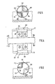
- the bearing portions 68 and 70 are rotatably mounted on the base 52. This can be seen best in Figures 4 to 6.
- the base 52 consists of the base plate 54 and cheeks 72 and 74 having respective semicircular bearing cut-outs 76 and 78 on both sides of the balance beam 12.
- the bearing portions 68 and 70 are mounted with respective cylindrical bearing surfaces 80 and 82 in the bearing cut-outs 76 and 78.
- the bearing portions 68 and 70 have respective projecting edges 84 and 86 on the outer sides and these edges engage respective outer sides of the cheeks 72 and 74.
- Brackets 88 and 90 are respectively formed at the bearing portions 68 and 70 on the side facing the balance beam 12.
- the brackets 88 and 90 have mutually orthogonal lateral surfaces 92,94 and 96,98, respectively.
- Brackets 100,102 are formed at the balance beam 12 on both sides thereof.
- the brackets 100 and 102 have also mutually orthogonal lateral surfaces 104,106 and 108,110, respectively.
- the leaf springs 60,62 and 64,66 are respectively attached with their other ends to a related one of the mutually orthogonal lateral surfaces 104,106 and 108,110. As can be seen in Fig.
- each one of the leaf springs 60,62 and 64,66 has enlarged ends 112,114 for attachment and a reduced central portion 116 such that, in the assembled state, the leaf springs, for example, leaf springs 60 and 62 extend around each other and the central portions 116 pass each other.
- the leaf springs 60,62 and 64,66 form flexural pivots by means of which the balance beam 12 is pivotably mounted.
- the bearing portions 68,70 with the balance beam 12 are supported such as to permit their removal from the base 52. By rotating the bearing portions 68 and 70, the balance beam 12 can be biased in one or the other direction, whereby zero adjustment is possible.
- the bearing portions 68 and 70 may be clamped in the adjusted position.
- the member 118 is a spring sheet metal blank having two spring tongues 122,124 and a central aperture 120 for the passage of the moving coil 38 and the balance beam 12.
- the spring sheet metal blank 118 engages the magnet 42 and is attached thereto by means of the screws 56.
- the spring tongues 122 and 124 respectively engage the bearing surfaces 80 and 82 of the bearing portions 68 and 70 on the side remote from the bearing cut-outs 76,78 and keep the bearing portions 68 and 70 in their adjusted positions.
- An air inlet port 126 is provided on the underside of the base plate 54.
- the air inlet port 126 communicates with a chamber 128 through the restrictor 24, which chamber 128 is formed by an O-ring 130 and a plate 132.
- the nozzle 22 is provided in the plate 132 and formed by a straight piece of tube communicating with the chamber 128.
- the nozzle 22 ends in front of the surface 26 which here is formed by a support for the moving coil 36.
- the plate 132 is tumblingly movable on the O-ring 130 and can be adjusted by means of screws 134 and thrust pieces 136 extending over the plate 132.
- the chamber 128 communication with a bore 140 in the base plate 54 through an annular passage 138 and this bore 140 constitutes the outlet port 28 (Fig. 1).
- balance beam 12 is centrosymmetrically formed relative to the center of mass.
Landscapes
- Engineering & Computer Science (AREA)
- Physics & Mathematics (AREA)
- Fluid Mechanics (AREA)
- Mechanical Engineering (AREA)
- General Engineering & Computer Science (AREA)
- Supply Devices, Intensifiers, Converters, And Telemotors (AREA)
- Manipulator (AREA)
- Transmission And Conversion Of Sensor Element Output (AREA)
- Amplifiers (AREA)
- Discharge Heating (AREA)
Claims (6)
caractérisé par le fait que
Priority Applications (1)
| Application Number | Priority Date | Filing Date | Title |
|---|---|---|---|
| AT84112428T ATE26746T1 (de) | 1983-11-26 | 1984-10-16 | Elektropneumatischer signalumformer. |
Applications Claiming Priority (2)
| Application Number | Priority Date | Filing Date | Title |
|---|---|---|---|
| DE3342857 | 1983-11-26 | ||
| DE19833342857 DE3342857A1 (de) | 1983-11-26 | 1983-11-26 | Elektro-pneumatischer umformer |
Publications (2)
| Publication Number | Publication Date |
|---|---|
| EP0147552A1 EP0147552A1 (fr) | 1985-07-10 |
| EP0147552B1 true EP0147552B1 (fr) | 1987-04-22 |
Family
ID=6215361
Family Applications (1)
| Application Number | Title | Priority Date | Filing Date |
|---|---|---|---|
| EP84112428A Expired EP0147552B1 (fr) | 1983-11-26 | 1984-10-16 | Convertisseur électropneumatique |
Country Status (6)
| Country | Link |
|---|---|
| US (1) | US4595029A (fr) |
| EP (1) | EP0147552B1 (fr) |
| JP (1) | JPS60143716A (fr) |
| AT (1) | ATE26746T1 (fr) |
| CA (1) | CA1226591A (fr) |
| DE (2) | DE3342857A1 (fr) |
Families Citing this family (5)
| Publication number | Priority date | Publication date | Assignee | Title |
|---|---|---|---|---|
| US5257639A (en) * | 1988-12-23 | 1993-11-02 | Dresser Industries, Inc. | Electropneumatic positioner |
| US4926896A (en) * | 1988-12-23 | 1990-05-22 | Dresser Industries, Inc. | Sensitive electrical to mechanical transducer |
| US5105791A (en) * | 1990-12-21 | 1992-04-21 | Nye Jr Dudley D | Current to pressure/vacuum transducer |
| DE4435108C2 (de) * | 1994-09-30 | 1997-10-02 | Samson Ag | Elektropneumatischer Wandler |
| GB9612750D0 (en) * | 1996-06-19 | 1996-08-21 | Watson Smith Ltd | Improvements relating to electric-to-pressure converters |
Citations (1)
| Publication number | Priority date | Publication date | Assignee | Title |
|---|---|---|---|---|
| DE2654003A1 (de) * | 1976-11-27 | 1978-06-01 | Vdo Schindling | Einrichtung zum umformen eines pneumatischen oder hydraulischen drucks in einen elektrischen strom und umgekehrt |
Family Cites Families (7)
| Publication number | Priority date | Publication date | Assignee | Title |
|---|---|---|---|---|
| US2750960A (en) * | 1951-04-11 | 1956-06-19 | Crane Co | Valve |
| GB797722A (en) * | 1954-09-14 | 1958-07-09 | Foxboro Co | Improvements in or relating to transducers |
| US3155104A (en) * | 1962-03-23 | 1964-11-03 | Johnson Service Co | Electric-pressure transducers |
| GB1211708A (en) * | 1967-03-30 | 1970-11-11 | Westinghouse Brake & Signal | Fluid metering device |
| US3589672A (en) * | 1969-02-18 | 1971-06-29 | Trans Lux Corp | Solenoid controlled valve and armature with adjustable bias |
| DE2264220B2 (de) * | 1972-12-30 | 1976-12-23 | Samson Ag, 6000 Frankfurt | Elektropneumatischer signalwandler |
| US4336819A (en) * | 1979-12-06 | 1982-06-29 | Yokogawa Electric Works, Ltd. | Pneumatic converter |
-
1983
- 1983-11-26 DE DE19833342857 patent/DE3342857A1/de not_active Withdrawn
-
1984
- 1984-10-16 EP EP84112428A patent/EP0147552B1/fr not_active Expired
- 1984-10-16 AT AT84112428T patent/ATE26746T1/de not_active IP Right Cessation
- 1984-10-16 DE DE8484112428T patent/DE3463290D1/de not_active Expired
- 1984-10-31 CA CA000466737A patent/CA1226591A/fr not_active Expired
- 1984-11-05 US US06/668,424 patent/US4595029A/en not_active Expired - Lifetime
- 1984-11-26 JP JP59248268A patent/JPS60143716A/ja active Pending
Patent Citations (1)
| Publication number | Priority date | Publication date | Assignee | Title |
|---|---|---|---|---|
| DE2654003A1 (de) * | 1976-11-27 | 1978-06-01 | Vdo Schindling | Einrichtung zum umformen eines pneumatischen oder hydraulischen drucks in einen elektrischen strom und umgekehrt |
Non-Patent Citations (1)
| Title |
|---|
| "Regelungstechnische Praxis", vol. 23 (1981), pages 201-206 * |
Also Published As
| Publication number | Publication date |
|---|---|
| DE3342857A1 (de) | 1985-06-05 |
| JPS60143716A (ja) | 1985-07-30 |
| US4595029A (en) | 1986-06-17 |
| EP0147552A1 (fr) | 1985-07-10 |
| ATE26746T1 (de) | 1987-05-15 |
| DE3463290D1 (en) | 1987-05-27 |
| CA1226591A (fr) | 1987-09-08 |
Similar Documents
| Publication | Publication Date | Title |
|---|---|---|
| US2338732A (en) | System for measuring force and acceleration | |
| EP0147552B1 (fr) | Convertisseur électropneumatique | |
| KR20070090116A (ko) | 서보 보상 가속도계 | |
| US3564923A (en) | Differential pressure measuring apparatus | |
| GB1599735A (en) | Top-loading balance | |
| US2688253A (en) | Pressure differential responsive device | |
| GB2202953A (en) | Weighing machine | |
| US4930588A (en) | Electronic balance | |
| US4938076A (en) | Target fluid flow indicator gauge | |
| CA1322464C (fr) | Indicateur de debit de fluide cible | |
| US4109738A (en) | Weighing apparatus including lever-connected compensation coil means | |
| US4213478A (en) | Transducer assembly providing pneumatic output proportional to electrical input signal | |
| US3153210A (en) | Electrical pressure transducer | |
| JPS5826042B2 (ja) | 電気・空気作動型電流↓−位置変換装置 | |
| US2694566A (en) | Force measuring device | |
| SE437430B (sv) | Beraggregat | |
| US4381670A (en) | Support system for hard bearing balancing machines | |
| EP0251766B1 (fr) | Appareil pour fournir une pression de gaz calibrée | |
| US4329910A (en) | Transducer assembly providing position output proportional to electrical input signal | |
| US2631599A (en) | Totalizing device provided with adjustable double-acting fulcrums | |
| SU508123A1 (ru) | Пневматический измерительный преобразователь теплотехнического параметра | |
| JP3279052B2 (ja) | 電子天びん | |
| US5309935A (en) | Device for converting an electric current signal into a mechanical correcting variable | |
| JPH0455254B2 (fr) | ||
| US4193054A (en) | Air flow transducer |
Legal Events
| Date | Code | Title | Description |
|---|---|---|---|
| PUAI | Public reference made under article 153(3) epc to a published international application that has entered the european phase |
Free format text: ORIGINAL CODE: 0009012 |
|
| AK | Designated contracting states |
Designated state(s): AT BE CH DE FR GB IT LI LU NL SE |
|
| 17P | Request for examination filed |
Effective date: 19850611 |
|
| 17Q | First examination report despatched |
Effective date: 19860418 |
|
| ITF | It: translation for a ep patent filed | ||
| GRAA | (expected) grant |
Free format text: ORIGINAL CODE: 0009210 |
|
| AK | Designated contracting states |
Kind code of ref document: B1 Designated state(s): AT BE CH DE FR GB IT LI LU NL SE |
|
| PG25 | Lapsed in a contracting state [announced via postgrant information from national office to epo] |
Ref country code: BE Effective date: 19870422 |
|
| REF | Corresponds to: |
Ref document number: 26746 Country of ref document: AT Date of ref document: 19870515 Kind code of ref document: T |
|
| REF | Corresponds to: |
Ref document number: 3463290 Country of ref document: DE Date of ref document: 19870527 |
|
| ET | Fr: translation filed | ||
| PG25 | Lapsed in a contracting state [announced via postgrant information from national office to epo] |
Ref country code: LU Free format text: LAPSE BECAUSE OF NON-PAYMENT OF DUE FEES Effective date: 19871031 |
|
| PLBE | No opposition filed within time limit |
Free format text: ORIGINAL CODE: 0009261 |
|
| STAA | Information on the status of an ep patent application or granted ep patent |
Free format text: STATUS: NO OPPOSITION FILED WITHIN TIME LIMIT |
|
| 26N | No opposition filed | ||
| REG | Reference to a national code |
Ref country code: CH Ref legal event code: PUE Owner name: FISHER CONTROLS INTERNATIONAL, INC. |
|
| NLS | Nl: assignments of ep-patents |
Owner name: FISHER CONTROLS INTERNATIONAL, INC. TE CLAYTON, MI |
|
| ITPR | It: changes in ownership of a european patent |
Owner name: CESSIONE;FISHER CONTROLS INTERNATIONAL INC. |
|
| REG | Reference to a national code |
Ref country code: GB Ref legal event code: 732 |
|
| REG | Reference to a national code |
Ref country code: FR Ref legal event code: TP |
|
| ITTA | It: last paid annual fee | ||
| EAL | Se: european patent in force in sweden |
Ref document number: 84112428.2 |
|
| PGFP | Annual fee paid to national office [announced via postgrant information from national office to epo] |
Ref country code: AT Payment date: 19961011 Year of fee payment: 13 |
|
| PGFP | Annual fee paid to national office [announced via postgrant information from national office to epo] |
Ref country code: CH Payment date: 19961023 Year of fee payment: 13 |
|
| PGFP | Annual fee paid to national office [announced via postgrant information from national office to epo] |
Ref country code: NL Payment date: 19961029 Year of fee payment: 13 |
|
| PG25 | Lapsed in a contracting state [announced via postgrant information from national office to epo] |
Ref country code: AT Free format text: LAPSE BECAUSE OF NON-PAYMENT OF DUE FEES Effective date: 19971016 |
|
| PG25 | Lapsed in a contracting state [announced via postgrant information from national office to epo] |
Ref country code: LI Free format text: LAPSE BECAUSE OF NON-PAYMENT OF DUE FEES Effective date: 19971031 Ref country code: CH Free format text: LAPSE BECAUSE OF NON-PAYMENT OF DUE FEES Effective date: 19971031 |
|
| PG25 | Lapsed in a contracting state [announced via postgrant information from national office to epo] |
Ref country code: NL Free format text: LAPSE BECAUSE OF NON-PAYMENT OF DUE FEES Effective date: 19980501 |
|
| REG | Reference to a national code |
Ref country code: CH Ref legal event code: PL |
|
| NLV4 | Nl: lapsed or anulled due to non-payment of the annual fee |
Effective date: 19980501 |
|
| PGFP | Annual fee paid to national office [announced via postgrant information from national office to epo] |
Ref country code: SE Payment date: 19991007 Year of fee payment: 16 |
|
| PGFP | Annual fee paid to national office [announced via postgrant information from national office to epo] |
Ref country code: FR Payment date: 19991011 Year of fee payment: 16 |
|
| PGFP | Annual fee paid to national office [announced via postgrant information from national office to epo] |
Ref country code: GB Payment date: 19991013 Year of fee payment: 16 |
|
| PG25 | Lapsed in a contracting state [announced via postgrant information from national office to epo] |
Ref country code: GB Free format text: LAPSE BECAUSE OF NON-PAYMENT OF DUE FEES Effective date: 20001016 |
|
| PG25 | Lapsed in a contracting state [announced via postgrant information from national office to epo] |
Ref country code: SE Free format text: THE PATENT HAS BEEN ANNULLED BY A DECISION OF A NATIONAL AUTHORITY Effective date: 20001030 |
|
| GBPC | Gb: european patent ceased through non-payment of renewal fee |
Effective date: 20001016 |
|
| EUG | Se: european patent has lapsed |
Ref document number: 84112428.2 |
|
| PG25 | Lapsed in a contracting state [announced via postgrant information from national office to epo] |
Ref country code: FR Free format text: LAPSE BECAUSE OF NON-PAYMENT OF DUE FEES Effective date: 20010629 |
|
| REG | Reference to a national code |
Ref country code: FR Ref legal event code: ST |
|
| PGFP | Annual fee paid to national office [announced via postgrant information from national office to epo] |
Ref country code: DE Payment date: 20031023 Year of fee payment: 20 |