EP0147818A2 - Circuit électronique pour la protection de systèmes de production couplés à une source d'énergie - Google Patents
Circuit électronique pour la protection de systèmes de production couplés à une source d'énergie Download PDFInfo
- Publication number
- EP0147818A2 EP0147818A2 EP84116044A EP84116044A EP0147818A2 EP 0147818 A2 EP0147818 A2 EP 0147818A2 EP 84116044 A EP84116044 A EP 84116044A EP 84116044 A EP84116044 A EP 84116044A EP 0147818 A2 EP0147818 A2 EP 0147818A2
- Authority
- EP
- European Patent Office
- Prior art keywords
- productive
- protection
- electronic circuit
- active elements
- power supply
- Prior art date
- Legal status (The legal status is an assumption and is not a legal conclusion. Google has not performed a legal analysis and makes no representation as to the accuracy of the status listed.)
- Granted
Links
Images
Classifications
-
- H—ELECTRICITY
- H02—GENERATION; CONVERSION OR DISTRIBUTION OF ELECTRIC POWER
- H02H—EMERGENCY PROTECTIVE CIRCUIT ARRANGEMENTS
- H02H3/00—Emergency protective circuit arrangements for automatic disconnection directly responsive to an undesired change from normal electric working condition with or without subsequent reconnection ; integrated protection
- H02H3/02—Details
- H02H3/021—Details concerning the disconnection itself, e.g. at a particular instant, particularly at zero value of current, disconnection in a predetermined order
Definitions
- the invention relates to a circuit for protection of productive systems coupled to a power supply.
- the productive system within its supply circuit, consitutes an electric load.
- the subject of this invention is a particular circuit whose peculiar realization, together with the disposition of the components, is able to stop any supply of the electric load, preventing in advance serious anomalies to the system (to which the circuit is appointed), and also to the operators.
- circuit breakers take care of this task but, for many technical reasons, such devices are not capable to assure the immediate intervention in interrupting the power supply circuit. Therefore serious damages may occur to the system, and it also creates a passive and expensive interruption in the particular working process of the machine coupled to the power supply because of the necessary restoration repairs to recouple the power supply. Besides there is poor safety against accidents for the surrounding operators with such prior art devices.
- the purpose of this invention is to obviate the mentioned -serious troubles by using electronic devices, each of them being known per se, but which turn out to be advantageously innovating as regards their operative assembling, with the result of their easy and fast realization and assembly, and with the increased efficiency of intervention. Also, the devices have a longer lifetime. All this brings also an evident economical advantage, such as reduction in costs, starting from the manufacturer; therefore prices become commercially competitive.
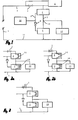
- 1 indicates the electric feeding or supply line.
- a well-known fuse 3 is set, which is provided with an inherent phase indicator 4.
- a gate or call device 6 below which a protection device 7 is placed, devices 6 and 7 being connected in series across the supply.
- Devices 6 and 7 have each a control input for supplying a control signal able to activate or bar the device.
- the control input of device 6 is connected via a cable 8 to a control circuit 10, the control input of device 7 is connected to cable 8 via an inverter 9.
- the lower branch 11 of the electric feeding line 1 is connected to a load 12, which as also coupled at a junction 13 to the above mentioned cable 5.
- Transistors of any kind and triacs make up the circuit, particularly the devices 6 and 7.
- the components present an advantageous installation rationally utilizing the two active devices which are functionally and conveniently coupled in opposition and in parallel to the line.
- the call device 6 is set to control the power supplied to load 12, receiving the signal from control circuit 10.
- the protection device 7, which is set in parallel with the above mentioned load 12, is also controlled by control circuit 10, but the control signal is inverted.
- the closing of the protection device 7 prevents any electric voltage from further reaching and activating load 12, since when both devices 6 - 7 are closed load 12 is inactivated (see Fig. 3).
- FIG. 2 shows the on/off operation which is illustrated as the connection of a couple of known switches 15/16, which are alternatively on and off, and the functional capabilities of the devices of "call” 6 and “protection” 7, as well as load 12 either active in on phase (Fig. 2a), or inactive with reference to load 12 (Fig. 3) corresponding to off phase.
- control circuit 10 takes care of the transitions of state of the above mentioned devices 6 and 7 and it does this extremely well, without any ambiguities, crossovers or various interferences during the transitions themselves.
Landscapes
- Emergency Protection Circuit Devices (AREA)
- Protection Of Static Devices (AREA)
- Direct Current Feeding And Distribution (AREA)
- Supply And Distribution Of Alternating Current (AREA)
- Amplifiers (AREA)
- Pretreatment Of Seeds And Plants (AREA)
Priority Applications (1)
| Application Number | Priority Date | Filing Date | Title |
|---|---|---|---|
| AT84116044T ATE38592T1 (de) | 1983-12-21 | 1984-12-21 | Elektronische schutzschaltung fuer produktionssysteme, die an eine energieversorgung gekoppelt sind. |
Applications Claiming Priority (2)
| Application Number | Priority Date | Filing Date | Title |
|---|---|---|---|
| IT68327/83A IT1160150B (it) | 1983-12-21 | 1983-12-21 | Circuito elettronico di protezione per impianti produttivi in genere |
| IT6832783 | 1983-12-21 |
Publications (3)
| Publication Number | Publication Date |
|---|---|
| EP0147818A2 true EP0147818A2 (fr) | 1985-07-10 |
| EP0147818A3 EP0147818A3 (en) | 1985-08-07 |
| EP0147818B1 EP0147818B1 (fr) | 1988-11-09 |
Family
ID=11308992
Family Applications (1)
| Application Number | Title | Priority Date | Filing Date |
|---|---|---|---|
| EP84116044A Expired EP0147818B1 (fr) | 1983-12-21 | 1984-12-21 | Circuit électronique pour la protection de systèmes de production couplés à une source d'énergie |
Country Status (4)
| Country | Link |
|---|---|
| EP (1) | EP0147818B1 (fr) |
| AT (1) | ATE38592T1 (fr) |
| DE (1) | DE3475148D1 (fr) |
| IT (1) | IT1160150B (fr) |
Cited By (3)
| Publication number | Priority date | Publication date | Assignee | Title |
|---|---|---|---|---|
| WO1992007402A1 (fr) * | 1990-10-12 | 1992-04-30 | Raychem Limited | Agencement de protection de circuit |
| US5319515A (en) * | 1990-10-12 | 1994-06-07 | Raychem Limited | Circuit protection arrangement |
| US6118641A (en) * | 1991-01-07 | 2000-09-12 | Raychem Limited | Overcurrent protection device |
Family Cites Families (3)
| Publication number | Priority date | Publication date | Assignee | Title |
|---|---|---|---|---|
| GB1293154A (en) * | 1968-11-08 | 1972-10-18 | Tokyo Keiki Kk | A switching device for power supply circuit |
| US3544720A (en) * | 1969-03-26 | 1970-12-01 | Mcintosh Lab Inc | Protective circuit for loudspeaker |
| US3668470A (en) * | 1970-12-28 | 1972-06-06 | Stanley Works | Device for detection and control of current leakage |
-
1983
- 1983-12-21 IT IT68327/83A patent/IT1160150B/it active
-
1984
- 1984-12-21 DE DE8484116044T patent/DE3475148D1/de not_active Expired
- 1984-12-21 EP EP84116044A patent/EP0147818B1/fr not_active Expired
- 1984-12-21 AT AT84116044T patent/ATE38592T1/de active
Cited By (5)
| Publication number | Priority date | Publication date | Assignee | Title |
|---|---|---|---|---|
| WO1992007402A1 (fr) * | 1990-10-12 | 1992-04-30 | Raychem Limited | Agencement de protection de circuit |
| US5319515A (en) * | 1990-10-12 | 1994-06-07 | Raychem Limited | Circuit protection arrangement |
| AU663473B2 (en) * | 1990-10-12 | 1995-10-12 | Raychem Limited | Circuit protection arrangement |
| US5625519A (en) * | 1990-10-12 | 1997-04-29 | Raychem Limited | Circuit protection arrangement |
| US6118641A (en) * | 1991-01-07 | 2000-09-12 | Raychem Limited | Overcurrent protection device |
Also Published As
| Publication number | Publication date |
|---|---|
| DE3475148D1 (en) | 1988-12-15 |
| IT8368327A1 (it) | 1985-06-21 |
| ATE38592T1 (de) | 1988-11-15 |
| EP0147818A3 (en) | 1985-08-07 |
| EP0147818B1 (fr) | 1988-11-09 |
| IT1160150B (it) | 1987-03-04 |
| IT8368327A0 (it) | 1983-12-21 |
Similar Documents
| Publication | Publication Date | Title |
|---|---|---|
| US11881813B2 (en) | Module switchoff device and security protection system of photovoltaic power generation system | |
| US7176653B2 (en) | Electric motor drive | |
| US4631627A (en) | Impulse operated relay system | |
| US4656365A (en) | Solid state power controller leakage current shunt circuit | |
| EP2940845A1 (fr) | Convertisseur pour une puissance électrique | |
| US5953189A (en) | Circuit for the protected power supply of an electrical load | |
| CN113677611A (zh) | 用于中断电梯设备的由供电装置供电的驱动机的扭矩生成的安全扭矩切断装置 | |
| EP0147818A2 (fr) | Circuit électronique pour la protection de systèmes de production couplés à une source d'énergie | |
| US10666043B2 (en) | Disconnection apparatus for a photovoltaic string, solar installation and operating method for a solar installation with a photovoltaic string | |
| US3846676A (en) | Electronic control system for remote control circuit breakers | |
| US5757088A (en) | Remote control device especially for conveying, spraying and distributing machines for concrete and mortar | |
| DE102007031882B4 (de) | Wäschebehandlungsgerät mit Türverriegelungselement | |
| US4359681A (en) | Alternating current power controller with DC transistor switching and an internal DC power supply | |
| EP0627808A2 (fr) | Système de commande d'un convertisseur électrique | |
| GB2059199A (en) | Control circuit arrangement for an induction motor with a clutch/brake unit | |
| KR102190205B1 (ko) | 인버터 보호장치 | |
| EP3930174B1 (fr) | Dispositif de protection d'onduleur | |
| US5390071A (en) | Low interference controlled switching circuit for multiple loads | |
| JPH066439Y2 (ja) | 無接点接触器 | |
| KR200315061Y1 (ko) | 3상 교류 전원의 돌입 전류 방지 장치 | |
| EP1309089B1 (fr) | Commutateur de puissance pour la commande du moteur d'une commande d'aiguillage | |
| GUSAN et al. | Implementation of safety systems in applications with collaborative robots | |
| US3260897A (en) | Protection device for plural phase electrical loads consisting of a plurality of monitoring relays controlling the energization of the load | |
| KR102287066B1 (ko) | 접점 개폐시 스위칭 아크의 발생을 방지하는 태양광 인버터 시스템 | |
| KR940006353Y1 (ko) | 삼상전동기 구동장치의 보호회로 |
Legal Events
| Date | Code | Title | Description |
|---|---|---|---|
| PUAI | Public reference made under article 153(3) epc to a published international application that has entered the european phase |
Free format text: ORIGINAL CODE: 0009012 |
|
| PUAL | Search report despatched |
Free format text: ORIGINAL CODE: 0009013 |
|
| AK | Designated contracting states |
Designated state(s): AT CH DE FR GB LI NL SE |
|
| AK | Designated contracting states |
Designated state(s): AT CH DE FR GB LI NL SE |
|
| 17P | Request for examination filed |
Effective date: 19860131 |
|
| 17Q | First examination report despatched |
Effective date: 19870219 |
|
| GRAA | (expected) grant |
Free format text: ORIGINAL CODE: 0009210 |
|
| AK | Designated contracting states |
Kind code of ref document: B1 Designated state(s): AT CH DE FR GB LI NL SE |
|
| REF | Corresponds to: |
Ref document number: 38592 Country of ref document: AT Date of ref document: 19881115 Kind code of ref document: T |
|
| REF | Corresponds to: |
Ref document number: 3475148 Country of ref document: DE Date of ref document: 19881215 |
|
| PGFP | Annual fee paid to national office [announced via postgrant information from national office to epo] |
Ref country code: DE Payment date: 19881221 Year of fee payment: 5 |
|
| PGFP | Annual fee paid to national office [announced via postgrant information from national office to epo] |
Ref country code: NL Payment date: 19881231 Year of fee payment: 5 |
|
| ET | Fr: translation filed | ||
| REG | Reference to a national code |
Ref country code: CH Ref legal event code: PFA Free format text: FASE SPA |
|
| PLBE | No opposition filed within time limit |
Free format text: ORIGINAL CODE: 0009261 |
|
| STAA | Information on the status of an ep patent application or granted ep patent |
Free format text: STATUS: NO OPPOSITION FILED WITHIN TIME LIMIT |
|
| 26N | No opposition filed | ||
| PG25 | Lapsed in a contracting state [announced via postgrant information from national office to epo] |
Ref country code: GB Effective date: 19891221 Ref country code: AT Effective date: 19891221 |
|
| PG25 | Lapsed in a contracting state [announced via postgrant information from national office to epo] |
Ref country code: SE Effective date: 19891222 |
|
| PG25 | Lapsed in a contracting state [announced via postgrant information from national office to epo] |
Ref country code: LI Effective date: 19891231 Ref country code: CH Effective date: 19891231 |
|
| PG25 | Lapsed in a contracting state [announced via postgrant information from national office to epo] |
Ref country code: NL Effective date: 19900701 |
|
| GBPC | Gb: european patent ceased through non-payment of renewal fee | ||
| NLV4 | Nl: lapsed or anulled due to non-payment of the annual fee | ||
| PG25 | Lapsed in a contracting state [announced via postgrant information from national office to epo] |
Ref country code: FR Effective date: 19900831 |
|
| REG | Reference to a national code |
Ref country code: CH Ref legal event code: PL |
|
| PG25 | Lapsed in a contracting state [announced via postgrant information from national office to epo] |
Ref country code: DE Effective date: 19900901 |
|
| REG | Reference to a national code |
Ref country code: FR Ref legal event code: ST |
|
| EUG | Se: european patent has lapsed |
Ref document number: 84116044.3 Effective date: 19900830 |