EP0147821A2 - Source lumineuse à plusieurs fonctions pour opérations dentaires - Google Patents
Source lumineuse à plusieurs fonctions pour opérations dentaires Download PDFInfo
- Publication number
- EP0147821A2 EP0147821A2 EP84116063A EP84116063A EP0147821A2 EP 0147821 A2 EP0147821 A2 EP 0147821A2 EP 84116063 A EP84116063 A EP 84116063A EP 84116063 A EP84116063 A EP 84116063A EP 0147821 A2 EP0147821 A2 EP 0147821A2
- Authority
- EP
- European Patent Office
- Prior art keywords
- light
- lamp
- light source
- illumination
- dental
- Prior art date
- Legal status (The legal status is an assumption and is not a legal conclusion. Google has not performed a legal analysis and makes no representation as to the accuracy of the status listed.)
- Withdrawn
Links
Images




Classifications
-
- A—HUMAN NECESSITIES
- A61—MEDICAL OR VETERINARY SCIENCE; HYGIENE
- A61C—DENTISTRY; APPARATUS OR METHODS FOR ORAL OR DENTAL HYGIENE
- A61C19/00—Dental auxiliary appliances
- A61C19/003—Apparatus for curing resins by radiation
-
- F—MECHANICAL ENGINEERING; LIGHTING; HEATING; WEAPONS; BLASTING
- F21—LIGHTING
- F21W—INDEXING SCHEME ASSOCIATED WITH SUBCLASSES F21K, F21L, F21S and F21V, RELATING TO USES OR APPLICATIONS OF LIGHTING DEVICES OR SYSTEMS
- F21W2131/00—Use or application of lighting devices or systems not provided for in codes F21W2102/00-F21W2121/00
- F21W2131/20—Lighting for medical use
- F21W2131/202—Lighting for medical use for dentistry
-
- Y—GENERAL TAGGING OF NEW TECHNOLOGICAL DEVELOPMENTS; GENERAL TAGGING OF CROSS-SECTIONAL TECHNOLOGIES SPANNING OVER SEVERAL SECTIONS OF THE IPC; TECHNICAL SUBJECTS COVERED BY FORMER USPC CROSS-REFERENCE ART COLLECTIONS [XRACs] AND DIGESTS
- Y10—TECHNICAL SUBJECTS COVERED BY FORMER USPC
- Y10S—TECHNICAL SUBJECTS COVERED BY FORMER USPC CROSS-REFERENCE ART COLLECTIONS [XRACs] AND DIGESTS
- Y10S362/00—Illumination
- Y10S362/804—Surgical or dental spotlight
Definitions
- Toothodonti presently requires illumination of as nearly as possible pure white light to be directed at dental targets for viewing the same such as the interior of an oral cavity; similar somewhat intensified white light illumination suitable for shade matching of artificial teeth with natural teeth; photocure light power of a type to effect curing of light-curable resins or plastics used for dental restorations of various kinds and similar purposes; 3 1 and illumination of dental targets of a type which permits viewing the same without effecting premature polymerization of visible light-curable resins or plastics, such as those used for dental restorations of various kinds and especially while forming and shaping fillings and similar restorations of plastic material prior to curing the same.
- lights or lamps to produce standard illumination now are available only as an individual units. As far as is known, a no-cure type of illumination is not available to date.
- the present invention utilizes a single lamp as a light source and by means of a series of light modifying optical filters and related elements, coupled with variable control of voltage to the filament of the light source, at least most if not all of the various types of dental applications for illumination and photocuring set forth above can be produced by relatively simple structures of a compact nature, details of which are set forth below.
- the present invention is the result of expanding and increasing the versatility and convenience of the inventions in applicant's prior United States Patent Number 4,385,344, dated May 24, 1983, and his pending United States application, Serial Number 492,286, filed May 6, 1983.
- a multi-function dental operatory light source in which, by simple rotation of a turntable on which a limited number of light beam modifiers of a single stationary light source are mounted for selective positioning relative to said light source and manual setting of a potentiometer and the electronic control circuitry therefor to vary the voltage to the filament of the light source as required for each modifier, whereby at least the most commonly required dental illumination needs and photocuring function are supplied by a single instrument.
- said single instrument selectively supply substantially pure white light to view dental targets, intensify said white light at a higher color temperature a limited amount for shade matching purposes simply by varying the aforementioned voltage to the lamp filament by adjusting said potentiometer, supply non-polymerizing light illumination for viewing dental materials which otherwise would light polymerize light-sensitive materials, and supplying polymerizing light capable of quickly polymerizing light-polymerizable resins and plastics when required, whereby simple rotation of the aforementioned turntable on which said several light-modifying optical devices are supported in spaced relationship produces the desired types of dental illumination and photocure function from a single light source.
- Another object of the invention is to provide a heat- absorbing filter positioned adjacent and in the path of the light beam emanating from the parabolic reflector, whereby the light beam is intercepted by the heat absorbing filter and produces relatively cool light, of reduced infrared wavelengths, and less thermal stress is placed upon the modifying optical filters when positioned in the light beam and in front of the reflector of the lamp.
- a further object of the invention is to provide as a light source a tungsten halogen lamp having a parabolic reflector to produce parallel light rays, and further to provide one or more light filters selectively positionable in the light path from the lamp and the reflector therefor.
- Beam- splitting flat mirrors also are positioned in the standard illumination beam and the no-cure beam which split the light beam into two separate light beams transmitted through said optical filters and reflect the same in separate directions respectively to spherical reflectors positioned at opposite sides of said lamp. Since each of the split beams are spaced apart, they reflect each of the beams forward, toward and through a fixed transparent window spaced forward from said lamp.
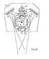
- Each of the separate light beams reflected from said spherical reflectors cross each other at a specified distance from said reflectors and are blended with the other beams to provide an illumination area of limited width and height at a location spaced forward from said window.
- the crossover of said light beams is at a range of distances at which a dentist normally positions an illuminating light source from a dental target such as an oral cavity.
- One reason for dual converging light beams is that, when a dentist is manipulating, it is possible to block one light beam with an arm, shoulder, hand, or head, whereby one light beam is left unblocked for illumination purposes.
- Still another object of the invention is to provide a base movably mounted relative to a dental chair in an operatory for desired positioning of said base relative to a patient in said chair, and said aforementioned turntable upon which said aforementioned beam-modifying optical filters are mounted and is rotatably supported upon said base for movement around an axis vertical to said base, and further providing releasable position-maintaining means between said turntable and base to firmly hold a selected.
- beam-modifying optical filter and associated beam-splitting flat reflectors in operable position adjacent said aforementioned lamp.
- a further object ancillary to the immediate foregoing object is to mount said lamp fixedly and centrally adjacent one side edge of the base, which preferably is a plate, and also fixedly position said aforementioned spherical reflectors adjacent said same side edge of said base plate and spaced from opposite sides of said lamp, and said aforementioned transparent window is fixed to the opposite side edge of said base plate.
- One further object of the invention is to enclose all of the elements set forth above in a housing fixed to said base plate and said base plate and housing _being pivotally supported relative to one end of a movably mounted arm, and manipulating handles being mounted upon said housing to facilitate positioning said base plate and housing as desired relative to a dental target.
- One other object of the invention is to provide a potentiometer in an electronic circuit to said aforementioned lamp which is operable selectively to vary voltage to the filament of said lamp as required to effect the functions of the various beam-modifying optical filters to operate in different wavelength ranges in nanometers, the potentiometer having a single manually operable knob which, in addition to the manual means by which the turntable is rotated, is the only other means requiring manual operation to effect the respective functions of the beam-modifying optical filters and the resin curing unit on the turntable.
- Still another object of the invention is to utilize optical filters and related mechanisms to change illumination emanating from a light source such as, for example, a tungsten halogen lamp which produces various desired Kelvin ranges respectively arranged to produce: white illumination between 4700°K and 5100°K for normal observation of dental targets; intensify the blue, green, and red toward the blue and thereby increase the lumens for shade matching to about 5500°K or in a range between 5400°K and 5900°K; reduce the color temperature to less than 1667°K and use the same with a filter which eliminates the blue range of the spectrum between 400 and 500 nm, and permits wavelength greater than 500 nm to pass through the optical filter, which renders polymerizing of visible light-polymerizable resins and plastics unaffected by the light.
- beams between 500 and 715 nm are not obstructed for viewing purposes and allow sufficient illumination to place and architecture restorative dental materials.
- the light source preferably is generated by electric current connected to a tungsten halogen lamp having a parabolic reflector, but other lamp types may be used such as various arc-type lamps which produce an acceptable optical spectrum.
- a tungsten halogen lamp found to be highly successful can be operated as high as 3400°K, but this is only exemplary and not restrictive.
- the various lights or illuminations designed to be produced by such lamp require the use of specific optical filters to achieve the objectives of the invention for different dental illuminations and for photocuring purposes.
- a heat absorbing filter preferably is positioned immediately in front of the lamp reflector in the liaht beam.
- all of the other optical filters are interference filters which either pass or reject certain wavelengths of light, as designed and desired.
- These optical filters comprise layers of certain materials selected for their known index of refraction and are laminated, for example, in a vacuum deposition chamber, and laid on a suitable substrate. Such optical filters shape the spectrum of a light beam passing therethrough to a desired portion or section of the optical spectrum for specific passage or rejection of light beams of various wavelengths.
- Light beams also have color temperature units expressed as K or Kelvins.
- the optical filter to produce substantially pure white light for normal illumination of dental targets from the reflector of the lamp referred to produces beams having a color temperature between 4700°K and 5100°K in the wavelength range between 400 and 715 nm and in which the blue, green, and red wavelength ranges are proportioned to produce pure white light.
- this temperature is increased to approximately 5500°K but with an adjustable range from 5400°K to 5900°K which is accomplished by increasing the voltage beyond the standard illumination range supplied to the filament of the lamp.
- a filter to produce a beam having a color temperature of less than 1667°K is used but the filter is one which eliminates the 400 to 500 nm wavelength range, yet retains light beams between the 500 and 715 nm wavelength range which is necessary for viewing purposes and allows placing and shaping the observed light-sensitive material such as visible light-curable filling or denture base resins or plastics.
- Such beams are in the yellow-red region of the spectrum.
- the invention includes a photocure heat reflecting band pass filter positionable opposite the parabolic reflector of the lamp, and heat absorbing filter which has a color temperature of less than 1667°K with its light flux primarily in the 400 to 500 nm wavelength range and rejects beams in the wavelength range between 500 and 715 nm.
- a fixedly mounted light-condensing cone is used to which an external supplemental light-condensing cone is attached by the operator when photocuring is required.
- another objective of the invention preferably is to project beams from the apparatus in a columnated form and of reasonable dimensions in area at a conventional distance of approximately in the range of between 24 and 37 inches between the dental target and the light source.
- One further object of the invention is to provide comfort and safety means for a patient, especially while the relatively strong photocure energy is directed toward the patient.
- This is in the form of a switch in the circuit to the light source lamp whereby, when the turntable is rotated to dispose the photocure light cone in the operative position relative to the lamp, said switch automatically is opened to deactivate the lamp while a supplemental external light- condensing cone is positioned manually upon the primary or internal light-condensing cone and during such operation, the light from the lamp cannot project the light into the patient's eyes.
- the circuit to the lamp also includes an additional, preferably push-button, switch which is actuated easily to restore current to the lamp after the external supplemental cone has been mounted operatively upon the internal primary cone and, still further, a timer of limited time duration also is in the lamp circuit and functions to disconnect current from the lamp after a pre-set time elapses, such as ten seconds duration, for example, thereby automatically limiting exposure by the photocure light beam.
- the above described push-button switch may be actuated repeatedly, however, to afford as much photocuring as required.
- the multi-function dental operating light source comprising the present invention be supported by the outer end of an appropriate arm 10 which extends either from a wall, ceiling, or post pedestal in an operatory.
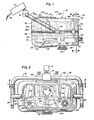
- a U -shape member 12 is connected by a swivel 14 to the outer end of arm 10 and it will be understood that an electrical supply cord is located in conduit 16 and extends from a suitable power line source, not shown, and appropriate electrical thermal breakers, current- limiting switch, and connect-disconnect switch and its wiring are located in said conduit which extends in conventional manner through the arm 10, swivel 14, and U-shape member 12 to the interior of the light head housing 18 which preferably comprises an upper section 20 and a lower section 22 that are detachably connected. Opposite sides of the housing 18 are connected by pivots 24 to the outer ends of member 12.
- the sections 20 and 22 of housing 18 preferably are molded from suitable, rigid plastic material for durability as well as to provide electrical insulation properties.
- a manually-engageable handle 26 extends from each of the opposite sides of the housing 18 for purposes of swivelling the housing to any desired location nd position for purposes of directing illumination or photocuring light beams therefrom to a dental target such as an oral cavity or tooth of a patient. It will be understood that the pivots 24 and swivel 14 have sufficient friction to maintain a desirable location and position of the housing 18 after the same has been adjusted to a working position.
- a description of the contents of the housing 18 is as follows.
- a base 28 which preferably is a plate substantially parallel to the meeting lines of sections 20 and 22 of the housing, said base plate preferably being of metal, such as aluminum, and may be anodized black or in color.
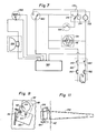
- a plurality of posts 30 extend perpendicularly in opposite directions from the base 28 as shown in Figure 9 which is substantially a side view of the base plate and shows the posts 30 better than if they would appear in Figure 1 if shown in phantom.
- the upper portions 32 of the posts are of a smaller diameter and extend through suitable holes in the base plate.
- the lower part of the upper portions 32 are threaded to receive clamping nuts 34 and accomplishes this without threading the entire portions 32 by the part thereof which receives the nuts 34 being of a slightly larger diameter than the upper part of said portions.
- the outer ends of the posts 30 and upper portions 32 have tapped holes 36 extending thereto for purposes of receiving connecting screws 38 which extend through bosses 40 shown in Figure 1 on the interior of the upper and lower sections 20 and 22 of the housing 18. From Figure 3, it also will be seen that there are four of the composite posts 30, 36, respectively adjacent the corners of the base 28 and these comprise the means for holding together the upper and lower sections 20 and 22 of the housing 18.
- the front wall of the housing 18 has a transparent window panel 42 which, in vertical elevation, is shown in Figure 2 in the forward portion of the housing 18 and has a bezel 44 surrounding the same.
- Said bezel has a continuous groove 46 extending thereinto as best seen in Figures 2 and 3 and said groove receives the edge portions of the transparent window panel 42 for purposes of securing it in operative position.
- the panel has a small opening or aperture 48 near the upper portion and midway between the opposite sides through which the photocuring light can pass when the same is open, details of which are described hereinafter.
- the opening 48 normally is closed except when the external light- condensing cone is mounted upon the primary internal cone, whereby its effects are employed to activate light-curable resins and the like when aligned with said opening.
- Closing of opening 48 is effected by a closure in the form of a pivoted plate 50 which is shown in edge view in Figure 3 in the lower portion of said figure.
- the closure 50 is supported upon a pivot bolt 52.
- a pin 54 which is attached thereto projects through the opening 48 as clearly shown in Figure 2. It is otherwise shown in Figure 3, where it will be seen that it is adequate for manual engagement.
- Closure 50 normally is maintained in closed position in a yieldable manner by means of return spring 56.
- the window panel 42 in each of the opposite upper corners thereof, is provided with clear transparent window portions 58 and, otherwise, the window panel 42 is opaqued, such as by painting the innersurface thereof or otherwise.
- the lower opposite corners of the window panel 40 also are provided respectively with holes through which a push-button actuator 60 and a shaft of a potentiometer extend.
- Base plate 28 supports a number of elements within housing 18, among the more important of which is a turntable 64 which is shown in plan view in Figure 3.
- the manner in which the turntable is supported upon the base 28 is best shown in Figure 10.
- Said base is provided with a preferably circular opening 66 into which a shouldered, preferably circular insulating insert member 68 is suitably affixed by spaced screws 70, certain of which are shown in Figures 3 and 10.
- Rotatable shaft 72 extends through a central opening in insulating member 68. Vertically spaced portions of the shaft 72 extend through axially aligned upper bushing member 74 and lower bushing member 76.
- the upper bushing member 74 has a circular flange 78 intermediately of the ends and lower bushing member 76 has only a lower circular flange 80.
- an upper anti-friction bearing 82 Positioned between the upper face of insulating member 68 and flange 78 is an upper anti-friction bearing 82 and disposed between the lower face of insulating member 68 and flange 80 of the lower bushing member 76 is a lower anti-friction bearing 84.
- a transverse pin 86 extends through the lower portions of upper bushing member 74 and shaft 72 and is of such length that it doesn't interfere with the anti-friction bearing 82.
- the bearing 82 then is mounted upon the upper bushing member 74 and the shaft is extended through hole 88 in insulating member 68.
- the lower anti-friction bearing 84 and lower bushing member 76 are mounted upon the shaft, followed by the mounting of a clamping collar 90 upon the shaft.
- the lower portion of shaft 72 also has a short flat 92 formed on one side thereof for engagement by a setscrew 95 threaded radially into the clamping collar 90.
- a nut is threaded onto the lower threaded end 94 of shaft 72 and is tightened against the axial assembly, following which setscrew 95 is threaded against the flat 92 to maintain the assembly in operative position, after which the tightening nut, not shown, is removed.
- Shaft 72 has a depending portion 96 which extends through the lower section 22 of housing 18 as shown in Figure 1 and to the projecting end thereof, a manually-engageable, rotatable knob 98 is affixed.
- the foregoing arrangement is for purposes of positioning the plurality of different beam- developing devices circumferentially mounted upon the turntable 64 relative to a light source, details of which are described hereinafter.
- Base 28 is fixedly mounted within the housing 18 by means of the details shown in Figure 9 and described hereinabove. Also supported fixedly upon said base plate is 8 lamp housing 100 provided with an insulating base insert 102 which receives and supports base plate 104 of a preferably tungsten halogen lamp 106 which has a parabolic reflector for purposes of producing a columnated light beam.
- the housing 100 has a pair of ears 108 which are secured by screws to the base 28 as clearly shown in Figure 3.
- Connected to insulating base insert 102 are a pair of electric wires 110 which are part of the electric cord 16.
- the forward portion of the lamp housing 100 has an opening through which the columnated light beams from the parabolic reflector of lamp 106 are projected and extending across that opening is a heat absorbing filter 112.
- a forced air cooling fan unit 114 supported adjacent an opening in the fixed base plate 28 and upon the lower surface thereof is a forced air cooling fan unit 114, shown in phantom in Figures 1 and 2 and in plan view in Figure 3, said unit including a bladed fan 160 which blows ambient room air directly through the housing 100 and in doing so draws air in through louvre 118 in the lower section 22 of the housing and discharges it through louvre 118 in the upper section 20 of housing 18.
- the electric motor of cooling fan 114 is connected in the circuit shown in Figure 7, details of which are described hereinafter.
- one of the highly important features of the present invention comprises the turntable 64, the mounting of which is described hereinabove, and of the light beam-modifying elements which are supported thereon for rotation therewith to dispose the same respectively in one of three operative positions relative to the fixed light source 106 which preferably is a tungsten halogen lamp but other lamps of suitable and similar capability to produce a suitable optical spectrum may be substituted therefore, if desired.
- the fixed light source 106 which preferably is a tungsten halogen lamp but other lamps of suitable and similar capability to produce a suitable optical spectrum may be substituted therefore, if desired.
- said specific type of lamp performs admirably for all of the purposes to which the present invention is directed.
- the base 28 supports a spring-actuated positioning unit 120 which releasably engages complimentary shallow recesses 122 in the periphery of the turntable 64 to accurately position the various beam-modifying optical elements.
- the first beam- modifying optical element or system comprises a perpendicular frame 124 which supports a perpendicular filter 126 adapted to develop from lamp 106 and adjacent reflectors a standard illuminating beam which is pure white and devoid of color hue. Opposite the frame 124 is a similar perpendicular frame 128, which supports a no-cure filter 129.
- the light beams from filters 126 and 129 when they individually are disposed adjacent the lamp 106 and in axial alignment thereof respectively are divided by angularly positioned reflecting flat mirrors or light beam-dividers 130 and 132 which are secured by means of a bracket through which screws 134 project for securing the brackets to the turntable 64.
- One set of such reflecting mirrors 130 and 132 are provided respectively for each of the filters 126 and 129.
- a diametrically extending light reflecting device comprising a frusto-conical light-condensing cone member 136.
- the light output end 138 of member 136 is smaller than the operative light input end which is shown in Figure 3 to be adjacent the lamp 106 for purposes of receiving columnated light rays from the parabolic reflector of lamp 106 which, after passing through heat absorbing filter 112 said beams pass through a heat reflecting and band pass filter 140 for purposes of reshaping the optical spectrum of the light- curing beam.
- the filter 126 is disposed adjacent the heat absorbing filter 112 and in immediate alignment with the parabolic reflector of tungsten halogen lamp 106. Adjacent the rear edge of the base, somewhat at the corners thereof, are a pair of spherical reflectors 144 and 146 which are shown better in Figure 3. These have been adjusted to receive light from the divided beams from the flat mirrors 130 and 132 which, in turn, reflect the light forward through the clear transparent window portions 58 of the front panel 42.
- the beams produced will be of a pure white nature, free of color hue due to the nature of a filter 126.
- the color temperature of the lamp 106 is approximately 3000°K.
- the filter 126 has a color temperature within the range 4700°K and 5100°K, the wave length range being between 400 nm and 715 nm.
- the same type of white light also is preferable for shade matching of artificial teeth relative to natural teeth or any other objects requiring color comparison but preferably such light must be of a higher color temperature such as of the order of 5500°K.
- This is produced also by optical filter 126 but the voltage to lamp 106 is increased by manipulating the knob 62 connected to potentiometer 150, see Figures 3 and 7.
- the illustration pertains to the no-cure illumination light beam and to produce this, the turntable 64 is rotated to position optical filter 129 opposite the lamp 106, where it will be held by means of one of the depressions 122 in the turntable engaging the spring- pressed ball detent of the positioning unit 120.
- Optical filter 129 is different from optical filter 126 in that it is designed to reject beams having wavelengths between 400 and 500 nm and therefor are not present in the light beam produced of the lamp whereby the resulting non-curing light beams are in the blue region of the visible spectrum and are incapable of polymerizing light-polymerizable plastic.
- the optical filter also is capable of passing the light beams between 500 and 715 nm for purposes of viewing light-curable material, without activating it, such as when the same is being placed, contoured, and characterized in a tooth or teeth.
- the passage of light beams between 500 and 715 nm is suitable for such illumination and viewing purposes and is in the yellow-red region of the visible spectrum.
- the light beams produced by the parabolic reflector of lamp 106 and filter 129 are reflected by the spherical reflectors 144 and 146 to project forward both the parallel light beams and those which cross at defined distances and ultimately result in producing an illuminating area 148 within the ranges stated with respect to optical filter 126 in Figure 4.
- the turntable 64 When photocuring function is to be produced by the invention, the turntable 64 is rotated to the position shown in Figures 3 and 6 in which the internal primary condensing. cone member 136 is disposed with the larger light input end adjacent the lamp 106 and the outer smaller light output end 138 thereof, immediately adjacent the opening 48 in the window panel 42.
- the light-condensing primary cone member 136 normally is not operated in the condition thereof shown in Figure 3 but preferably must have a supplemental externally mounted light-condensing cone member 152, shown in Figure 11, and the larger end thereof is mounted by friction or otherwise upon the small outer end 138 of member 136, as also shown in Figure 11.
- support 154 is fixed at its lower end to turntable 64 and, in addition to supporting the heat reflecting and band pass filter 140, also supports the larger inner end of the primary light-condensing cone member 136, while the smaller end 138 thereof is supported by a bracket 156 and is attached by screws to turntable 164 as clearly shown in the lower portion of Figure 3.
- the interior of light-condensing cone member 136 has a highly specular light-reflective surface which, for convenience, for example, may comprise a highly polished electrobrightened aluminum interior liner, and similarly, such liner lines the inner wall of the supplemental external light-condensing cone member 152 which, when rendered operative, is extended through the small opening 48 in the window panel 42 and then is mounted upon the small end 138 of internal light-condensing cone member 136.
- a highly specular light-reflective surface which, for convenience, for example, may comprise a highly polished electrobrightened aluminum interior liner, and similarly, such liner lines the inner wall of the supplemental external light-condensing cone member 152 which, when rendered operative, is extended through the small opening 48 in the window panel 42 and then is mounted upon the small end 138 of internal light-condensing cone member 136.
- a substantial amount of columnation of light rays from the reflector of lamp 106 occurs when mounted as shown by phantom lines illustrated in Figure 6 by the beams delivered from the discharge end of supplemental external light-condensing cone member 152 which diverge only to a limited extent of about ⁇ 10° from the optical axis in order to provide greater penetration of a light-curing beam into light-polymerizable or photocurable plastic material.
- a low light ray divergence angle is desirable for purposes of activating the same and thereby produce a rigid dental restoration having a greater depth of cure.
- the tip or outer end 158 is disposed relatively close to the dental target which is to be activated by the light energy emanating therefrom.
- the turntable When the turntable is disposed in the position shown in Figures 3 and 6, wherein the member 136 is in active position for receiving beams from the lamp 106 and assuming that the member 136 is directed toward a patients face such, for example, as when it is positioned for purposes of having the supplemental member 152 affixed thereto, the intense light emanating from the internal primary light-condensing cone member 136 is very bright and would present a safety problem as well as being very annoying to a patient if directed thereto. To prevent this from occurring, the invention contemplates the use of a disconnecting switch 160, best shown in Figures 3 and 7, which has an actuating finger 162 engaged by a camming roller 164 which is shown adjacent the finger 162 in Figure 3.
- an additional switch 166 is actuated by push-button 60 to re-establish the current to the lamp 106 and also actuate timer motor 172 for the purpose of creating light beams 168 which are of a light-curing nature and emanate from the light output end 158 of the external light-condensing cone member 152.
- the switch 166 is also shown in Figure 7 in the circuit diagram. The foregoing arrangement is for safety purposes as well as providing comfort to a patient.
- the present invention also contemplates the use of a timer 170, shown diagrammatically in Figure 7 as a synchronous motor 172 which operates a rotatable cam 174 that is engageable with the switch arm 176 of the timer 170.
- the timer 170 also is shown in phantom in Figure 3 adjacent the spherical reflector 134 and said timer is of the type that preferably is set for a fixed period of operation, such as ten seconds or any other fixed period which might be considered the preferred period of a so called "dose" time to assure safety and efficacy of the product. If at the end of such fixed period, additional curing is desired, it is only necessary to press again the push-button 60 of switch 166.
- FIG 12 there is illustrated a highly reflective sleeve 178 which connects to or fits over the small end of the external light-reflective cone member 152 and terminates in a forwardly extending reflective point 180 which is shown in cross-section in Figure 13, as seen on the line 13-13 in Figure 12.
- a highly reflective sleeve 178 which connects to or fits over the small end of the external light-reflective cone member 152 and terminates in a forwardly extending reflective point 180 which is shown in cross-section in Figure 13, as seen on the line 13-13 in Figure 12.
- Such an arrangement under certain circumstances gives a type of concentration and direction of the beam which is found desirable for certain types of photocuring of light-curable material in locations of difficult access within an oral cavity, such as posterior teeth.
- the outer end of member 15 as provided with a quartz, plastic, or fiber-optic light "tube” 182, which preferably is solid or may be in the form of fibers and has one end fitting into the outer end of external cone member 152 and beams therefrom are directed from the light output end 184 of the light "tube” 182 and it is especially useful for light-curing material within an oral cavity for example, such as a light-activated filling or coating material located in the posterior region of an oral cavity.
- the printed circuit shown in Figure 7 also includes a printed circuit board 186, details of which are not illustrated but it contains electronic elements which are connected by a circuit for a number of different purposes such as regulating the voltage to the lamp 106, providing a soft start for the flow of current to the lamp 106, such as of the order of a few seconds, to provide long life for the lamp; maintaining the voltage constant to the filament of the lamp regardless of power line fluctuations, also maintaining the light output from the lamp constant, not only for all power line voltage fluctuations described above but especially for photocuring, as when light-condensing cone members 136 and 152 are receiving light rays from the reflector of lamp 106 for delivery of the same to the target.
- the contents of the printed circuit board also replace expensive and heavy, bulky transformers.
- the circuits shown in Figure 7 include a master switch 188 which is manually operated such as when the operation of the light source of the invention is desired to provide illumination and photocuring light power of the type and ranges for which it is capable of producing. It is preferred that the switch 188 be mounted in a remote location from the housing 18 and, for example, may be mounted upon the terminable end of arm yoke 10 located on the U-shaped member 12 or otherwise.
- the housing of the switch also includes a double-throw manual switch 190 in which the arms are held together.
- a circuit breaker disconnect switch 192 is located at the post or input end of the arm and is included in each of the power lines through the switch members 190.
- a ground wire 194 is provided.
- a stop 196 is fixed to the base 28 adjacent the window panel 42 and when the turntable is turned 90° in either direction relative to said stop, either the camming roller 164 engages the stop to prevent further rotation such as when the filter 126 is disposed adjacent the lamp 106 or a further abutment 198, see Figure 3 adjacent the spring-actuated positioning ball check device 120, is fixed to the turntable 64 and abuts the stop member 196 on base 28 and prevents any further movement such as when the filter 130 has been disposed adjacent the reflector of lamp 106. Accordingly, it will be seen that the turntable 64 moves only through 180° comprising two excursions of 90° each.
- the present invention provides a compact and highly efficient dental operating light source by which at least three different types of illumination and one type of photocuring light power can be delivered in a dental operatory relative to dental targets.
- These types of illumination and photocure light power are normal white light free of color hue for general dental observation, intensified white light at a higher color temperature for shade matching and comparing function, no-cure illumination for use in observing light-curable plastic but without activating the same, and light-curing or photocuring light power for purposes of activating light-curable plastics.
- the structure occupies a relatively small space in a dental operatory as compared to three or four separate light sources respectively for purposes of providing the three types of illumination and one type of photocuring light power enumerated above. Because of circuitry of advanced design, the tungsten halogen lamp with a parabolic reflector is assured of reasonably long life under circumstances where the current to the lamp is constantly turned on and off, and all of the different optical functions are guarded against power line voltage fluctuations so as to deliver constant light output from the lamp. All of the various light beam-modifying structures are compactly housed within a space in which they are amply protected and columnation of the light beams directed from the front window panel are reasonably preserved.
- the housing or casing which, preferably, is adjustably mounted on the distal end of a supporting arm is adaptable to various types of mountings presently available for use in dental operatories.
- Two manually operable handles are provided which extend from the housing to allow for manual pivotal and swivelled positioning of the housing relative to a patient.
- a safety means is provided for the photocure function.
- FIGs. 15A, 15 B and 15C there are shown plan views of an alternate embodiment, wherein a different turntable arrangement is utilized for providing a different combination of selectable light modes, i.e., forms of light delivery.
- the turntable is rotatable in a manner as set forth above, to provide different combinations of light outputs in accordance with the elements that are brought into the path of the light source at the respective turntable positions.
- Fig. 15A shows the turntable in a position to generate three light beams for general illumination, plus a light pipe output for transillumination of small target areas.
- the potentiometer 150 (Fig. 3) is set by the operator to provide a voltage setting of, e.g., 32, 35, or 38 volts, corresponding to a bulb temperature of about 2864°K, 3009°K, or 3075°K respectively.
- a pair of reflector mirrors 230, 232 mounted on a support 236 are positioned to reflect light from collimated source 20fi toward and off of sperical reflectors 244, 246, to provide two converging beams.
- support 236 contains a slot, or window 237 positioned just below reflectors 230, 232, as further illustrated in Fig. 16.
- This slot permits a portion of the light from source 206 to pass directly through above the center of the turntable.
- Much of the beam passes through to focusing lens 245, which is held in position by support 247 having a window 248.
- the lens and window are positioned to direct the center beam of light so that it substantially meets with the two converging side beams at a predetermined distance.
- Fig. 15A is also shown in Fig. 15A is the input end 270 of a light pipe 278, having an input tip 271 positioned to collect slightly off axis light from the center beam.
- the lamp 106 produces substantially collimated light, but some light necessarily diverges off axis, and tip 271 is positioned slightly off the axis of the center beam.
- the light pipe is connected mechanically to cover 274 through ring or collar 275, the main portion of light pipe 278 being flexible and of a sufficient length to enable the dentist to direct the output end 280 at any desired target location.
- the input tip collects essentially off axis light from the center beam, while the bulk of the collimated portion of the beam passes on to and through window 248.
- the light pipe 278 thus provides additional ability to capture the off axis light of the center beam, e.g., an operator can additionally direct the light pipe output to transilluminate tissues in the oral cavity, such as a tooth, or the light pipe may be used for high intensity spot illumination, such as in the posterior areas of the oral cavity.
- the turntable 264 is shown rotated into another position so as to provide only a photocure light for light curing procedures.
- the lamp is preferrably operated at 47 volts, corresponding to a lamp temperature of about 3254 * K.
- the collimated light from source 206 is condensed and direced into the tip portion 270 of light pipe 278, providing intensified light for purposes of light curing of a restoration.
- a condensing means particularly adapted for this application comprises aspheric lens 250 and biconvex lens 256. This combination provides a very short focal length condensing means of the collimated light, e.g., 1 cm distance, and directs it into the tip 271 of the receiving portion 270 of the light pipe.
- a band pass filter passing visible light in a range of about 400 - 500 nm is mounted between aspheric lens 250 and the biconvex lens 256. Further, a shield 252 prevents scattering of light from the aspheric lens toward either reflector 244 or 246, ensuring that no light is directed toward the patient from those reflectors. Any straight ahead light is blocked by the back side of mirror support 261. Thus, the high intensity cure light is available through the light pipe, while at the same time the patient is shielded from any other light beam being directed on his or her face. As illustrated in Fig.16, the light pipe 278 is flexible, and can be manipulated by the operator to direct the output end 280 at any desired target, e.g., a photocurable restorative that has been placed in a patient's tooth.
- any desired target e.g., a photocurable restorative that has been placed in a patient's tooth.
- Fig. 15 C there is shown a third position of turntable 264, providing for two converging beams reflected from reflectors 244, 246, the beams being filtered additionally by color correction filter 260 for shade matching purposes.
- Filter 260 is illustrated in a position directly in front of source 206, and is designed to modify the source light spectrum from the parabolic reflector such that the visible light power distribution in the beams delivered to the target meet the color rendering index greater than 90 required for shade matching of teeth, particularly for matching of new artificial teeth to natural or tooth surfaces, as described above in connection with the embodiment of Fig. 4.
- Mirrors 262, 263 are also rotated into position, to reflect light off of reflectors 244 and 246, thereby generating two converging beams for the shade match application.
- the lamp is operated at a voltage of about 41 volts, corresponding to a lamp temperature of about 3175°K.
Landscapes
- Health & Medical Sciences (AREA)
- Oral & Maxillofacial Surgery (AREA)
- Dentistry (AREA)
- Epidemiology (AREA)
- Life Sciences & Earth Sciences (AREA)
- Animal Behavior & Ethology (AREA)
- General Health & Medical Sciences (AREA)
- Public Health (AREA)
- Veterinary Medicine (AREA)
- Non-Portable Lighting Devices Or Systems Thereof (AREA)
- Dental Tools And Instruments Or Auxiliary Dental Instruments (AREA)
Applications Claiming Priority (2)
| Application Number | Priority Date | Filing Date | Title |
|---|---|---|---|
| US06/566,235 US4516195A (en) | 1983-12-28 | 1983-12-28 | Multi-function dental operating light source |
| US566235 | 1983-12-28 |
Publications (2)
| Publication Number | Publication Date |
|---|---|
| EP0147821A2 true EP0147821A2 (fr) | 1985-07-10 |
| EP0147821A3 EP0147821A3 (fr) | 1987-05-13 |
Family
ID=24262060
Family Applications (1)
| Application Number | Title | Priority Date | Filing Date |
|---|---|---|---|
| EP84116063A Withdrawn EP0147821A3 (fr) | 1983-12-28 | 1984-12-21 | Source lumineuse à plusieurs fonctions pour opérations dentaires |
Country Status (4)
| Country | Link |
|---|---|
| US (1) | US4516195A (fr) |
| EP (1) | EP0147821A3 (fr) |
| JP (1) | JPS60227302A (fr) |
| CA (1) | CA1256838A (fr) |
Cited By (5)
| Publication number | Priority date | Publication date | Assignee | Title |
|---|---|---|---|---|
| DE3843254A1 (de) * | 1988-12-22 | 1990-07-12 | Emda | Zahnaerztliche mehrzweckleuchte |
| EP0361976A3 (en) * | 1988-09-30 | 1990-09-12 | Den-Tal-Ez, Inc. | Miniature hand-held spot source of illumination |
| DE3911626A1 (de) * | 1989-04-09 | 1990-10-25 | Emda Dental Systeme Gmbh | Zahnaerztliche mehrzweckleuchte |
| EP1880692A1 (fr) * | 2006-07-21 | 2008-01-23 | CASTELLINI S.p.A. | Dispositif d'illumination à changement de couleur pour le domaine dentaire |
| WO2013135516A1 (fr) | 2012-03-14 | 2013-09-19 | Giebeler Uwe | Procédé et dispositif permettant d'éclairer un champ de travail dans le cadre d'un traitement médical avec mise en œuvre de matériaux durcissant à la lumière |
Families Citing this family (26)
| Publication number | Priority date | Publication date | Assignee | Title |
|---|---|---|---|---|
| JPS62200312U (fr) * | 1986-06-13 | 1987-12-21 | ||
| US5115307A (en) * | 1987-03-05 | 1992-05-19 | Fuji Optical Systems | Electronic video dental camera |
| US5251025A (en) * | 1987-03-05 | 1993-10-05 | Fuji Optical Systems, Inc. | Electronic video dental camera |
| JPH01100303U (fr) * | 1987-12-25 | 1989-07-05 | ||
| US5051823A (en) * | 1988-01-28 | 1991-09-24 | Fuji Optical Systems, Inc. | Dental instrument including laser device and electronic video dental camera |
| US4837668A (en) * | 1988-01-28 | 1989-06-06 | Koehler Joseph P | Reflector for dental or medical light |
| US5003434A (en) * | 1988-09-30 | 1991-03-26 | Den-Tal-Ez, Inc. | Miniature hand-held spot source of illumination |
| USD351676S (en) | 1993-02-03 | 1994-10-18 | Siemens Aktiengesellschaft | Work zone light for medical purposes |
| CA2137632A1 (fr) * | 1993-12-17 | 1995-06-18 | Douglas S. Dunn | Methode d'imagerie ablative utilisant une lampe-eclair |
| USD366712S (en) | 1994-03-29 | 1996-01-30 | Vari-Lite, Inc. | Adjustable spot luminaire |
| US6201880B1 (en) | 1996-12-31 | 2001-03-13 | Electro-Optical Sciences | Method and apparatus for electronically imaging a tooth through transillumination by light |
| WO2002056787A2 (fr) * | 2000-11-28 | 2002-07-25 | Den-Mat Corporation | Lampe halogene de polymerisation presentant des proprietes optiques ameliorees |
| US6900742B2 (en) * | 2002-02-19 | 2005-05-31 | Little Circuits, Inc. | Light control module for aviation obstruction marking |
| US6773261B2 (en) * | 2002-06-28 | 2004-08-10 | 3M Innovative Properties Company | Processes for forming dental materials |
| US7134875B2 (en) * | 2002-06-28 | 2006-11-14 | 3M Innovative Properties Company | Processes for forming dental materials and device |
| US20050164144A1 (en) * | 2004-01-27 | 2005-07-28 | Kerr Corporation | Shade lamp and method |
| WO2006047866A1 (fr) * | 2004-11-01 | 2006-05-11 | Uview Ultraviolet Systems Inc. | Appareil et procede de durcissement de materiaux revetant une surface |
| US8016470B2 (en) * | 2007-10-05 | 2011-09-13 | Dental Equipment, Llc | LED-based dental exam lamp with variable chromaticity |
| DE102005036275A1 (de) * | 2005-08-02 | 2007-02-08 | Berchtold Holding Gmbh | Operationsleuchte |
| US20070031777A1 (en) * | 2005-08-03 | 2007-02-08 | Bwt Property, Inc. | Multifunctional Dental Apparatus |
| DE102005061204A1 (de) * | 2005-12-21 | 2007-07-05 | Perkinelmer Elcos Gmbh | Beleuchtungsvorrichtung, Beleuchtungssteuergerät und Beleuchtungssystem |
| US7665875B2 (en) * | 2008-02-21 | 2010-02-23 | Rick Whitman | Articulating dental operatory light |
| US8070322B2 (en) * | 2008-09-11 | 2011-12-06 | Dental Equipment, Llc | Examination light with readily accessible controls |
| DE102009003151A1 (de) * | 2009-05-15 | 2010-11-18 | Habdank Pv-Montagesysteme Gmbh & Co. Kg | Traganordnung für Solarmodule |
| US9681799B1 (en) * | 2016-05-26 | 2017-06-20 | Dental Smartmirror, Inc. | Controlling an intraoral mirror with an integrated camera, and applications thereof |
| ES2900073T3 (es) * | 2019-03-06 | 2022-03-15 | Ivoclar Vivadent Ag | Dispositivo de polimerización y postratamiento |
Family Cites Families (13)
| Publication number | Priority date | Publication date | Assignee | Title |
|---|---|---|---|---|
| FR792629A (fr) * | 1935-07-17 | 1936-01-07 | Anciens Ets Barbier | Appareil d'éclairage |
| US2606477A (en) * | 1949-05-07 | 1952-08-12 | Twentieth Cent Fox Film Corp | Apparatus for the projection of pictures in black and white or in color |
| US2699536A (en) * | 1950-06-22 | 1955-01-11 | Grant V W Roth | Combination signal headlight |
| US3202811A (en) * | 1961-06-23 | 1965-08-24 | Bausch & Lomb | Laboratory sun simulator |
| US3179791A (en) * | 1962-04-16 | 1965-04-20 | Philip J Mole | Illuminating device for producing varied color effects |
| GB1372024A (en) * | 1970-10-07 | 1974-10-30 | Oram J A | Lighting device |
| US3842254A (en) * | 1972-11-29 | 1974-10-15 | American Optical Corp | Illuminating system for contact lens ophthalmometer |
| AR205016A1 (es) * | 1974-02-11 | 1976-03-31 | Nath G | Dispositivo de iluminacion con un conductor de luz flexible que contiene un tubo flexible |
| DE2604921C3 (de) * | 1976-02-09 | 1984-03-08 | W.C. Heraeus Gmbh, 6450 Hanau | Beleuchtungseinrichtung für medizinische oder zahnärztliche Zwecke |
| US4196460A (en) * | 1978-07-14 | 1980-04-01 | Sybron Corporation | Major surgical light |
| DE3012340C2 (de) * | 1980-03-29 | 1984-06-20 | W.C. Heraeus Gmbh, 6450 Hanau | Operationsleuchte |
| US4385344A (en) * | 1980-08-29 | 1983-05-24 | Dentsply Research & Development Corp. | Visible light apparatus for curing photo-curable compositions |
| US4450139A (en) * | 1982-05-03 | 1984-05-22 | Solid State Systems, Corporation | Light generating apparatus for curing dental restorative composites |
-
1983
- 1983-12-28 US US06/566,235 patent/US4516195A/en not_active Expired - Fee Related
-
1984
- 1984-11-23 CA CA000468472A patent/CA1256838A/fr not_active Expired
- 1984-12-21 EP EP84116063A patent/EP0147821A3/fr not_active Withdrawn
- 1984-12-28 JP JP59281966A patent/JPS60227302A/ja active Pending
Cited By (6)
| Publication number | Priority date | Publication date | Assignee | Title |
|---|---|---|---|---|
| EP0361976A3 (en) * | 1988-09-30 | 1990-09-12 | Den-Tal-Ez, Inc. | Miniature hand-held spot source of illumination |
| DE3843254A1 (de) * | 1988-12-22 | 1990-07-12 | Emda | Zahnaerztliche mehrzweckleuchte |
| DE3911626A1 (de) * | 1989-04-09 | 1990-10-25 | Emda Dental Systeme Gmbh | Zahnaerztliche mehrzweckleuchte |
| EP1880692A1 (fr) * | 2006-07-21 | 2008-01-23 | CASTELLINI S.p.A. | Dispositif d'illumination à changement de couleur pour le domaine dentaire |
| WO2013135516A1 (fr) | 2012-03-14 | 2013-09-19 | Giebeler Uwe | Procédé et dispositif permettant d'éclairer un champ de travail dans le cadre d'un traitement médical avec mise en œuvre de matériaux durcissant à la lumière |
| DE102012102153A1 (de) * | 2012-03-14 | 2013-09-19 | Uwe Giebeler | Verfahren und Vorrichtung zur Beleuchtung eines Arbeitsfeldes im Zuge einer medizinischen Behandlung unter Einsatz lichthärtender Werkstoffe |
Also Published As
| Publication number | Publication date |
|---|---|
| US4516195A (en) | 1985-05-07 |
| JPS60227302A (ja) | 1985-11-12 |
| EP0147821A3 (fr) | 1987-05-13 |
| CA1256838A (fr) | 1989-07-04 |
Similar Documents
| Publication | Publication Date | Title |
|---|---|---|
| US4516195A (en) | Multi-function dental operating light source | |
| US4608622A (en) | Multi-function light source | |
| US3930149A (en) | Variable intensity dental light | |
| US6939009B2 (en) | Compact work light with high illumination uniformity | |
| US4445858A (en) | Apparatus for photo-curing of dental restorative materials | |
| US4952143A (en) | Dental bleaching instrument | |
| US20090122536A1 (en) | Operational lamp | |
| US7938643B2 (en) | Use of integrating sphere technology to provide uniform, high-intensity light, and wavelength mixing from light emitting diodes | |
| US6513954B2 (en) | Rainbow projection light | |
| EP1148860A1 (fr) | Systeme d'eclairage concu notamment a des fins chirurgicales | |
| JP3264671B2 (ja) | 昼光スペクトル発生ランプ | |
| AU2004317799A1 (en) | Flashlight for forming uniform image | |
| US6666565B2 (en) | Light emitting diode (LED) flashlight | |
| US20080025013A1 (en) | Led-powered dental operatory light | |
| WO1989008476A1 (fr) | Systeme portatif de dosage de la lumiere | |
| US3626170A (en) | Dental or surgical operating light | |
| US5274535A (en) | Dental operating light with color correction | |
| US2494058A (en) | Lighting unit | |
| US20070037113A1 (en) | Dental curing light including a light integrator for providing substantially equal distribution of each emitted wavelength | |
| US1321521A (en) | Machine fob photogbaphic lighting | |
| JP3084178U (ja) | 無影灯 | |
| CN208207348U (zh) | 一种手术显微镜 | |
| GB2420172A (en) | Lamp with air cooling and heat sink | |
| EP3569926B1 (fr) | Lampe scyalitique | |
| US2540577A (en) | Dental operating lamp |
Legal Events
| Date | Code | Title | Description |
|---|---|---|---|
| PUAI | Public reference made under article 153(3) epc to a published international application that has entered the european phase |
Free format text: ORIGINAL CODE: 0009012 |
|
| AK | Designated contracting states |
Designated state(s): CH DE FR GB IT LI NL SE |
|
| PUAL | Search report despatched |
Free format text: ORIGINAL CODE: 0009013 |
|
| AK | Designated contracting states |
Kind code of ref document: A3 Designated state(s): CH DE FR GB IT LI NL SE |
|
| STAA | Information on the status of an ep patent application or granted ep patent |
Free format text: STATUS: THE APPLICATION IS DEEMED TO BE WITHDRAWN |
|
| 18D | Application deemed to be withdrawn |
Effective date: 19871114 |
|
| RIN1 | Information on inventor provided before grant (corrected) |
Inventor name: GONSER, DONALD I. |