EP0147866B1 - Plattenwärmetauscher - Google Patents
Plattenwärmetauscher Download PDFInfo
- Publication number
- EP0147866B1 EP0147866B1 EP19840116425 EP84116425A EP0147866B1 EP 0147866 B1 EP0147866 B1 EP 0147866B1 EP 19840116425 EP19840116425 EP 19840116425 EP 84116425 A EP84116425 A EP 84116425A EP 0147866 B1 EP0147866 B1 EP 0147866B1
- Authority
- EP
- European Patent Office
- Prior art keywords
- heat exchanger
- plate
- plates
- fine structure
- plate heat
- Prior art date
- Legal status (The legal status is an assumption and is not a legal conclusion. Google has not performed a legal analysis and makes no representation as to the accuracy of the status listed.)
- Expired
Links
- 239000000463 material Substances 0.000 claims description 19
- XAGFODPZIPBFFR-UHFFFAOYSA-N aluminium Chemical compound [Al] XAGFODPZIPBFFR-UHFFFAOYSA-N 0.000 description 2
- 229910052782 aluminium Inorganic materials 0.000 description 2
- 239000004411 aluminium Substances 0.000 description 2
- 230000000694 effects Effects 0.000 description 2
- 230000002349 favourable effect Effects 0.000 description 2
- 238000004519 manufacturing process Methods 0.000 description 2
- 238000000034 method Methods 0.000 description 2
- 210000002445 nipple Anatomy 0.000 description 2
- 238000011084 recovery Methods 0.000 description 2
- 238000009423 ventilation Methods 0.000 description 2
- 239000000853 adhesive Substances 0.000 description 1
- 230000001070 adhesive effect Effects 0.000 description 1
- 230000009286 beneficial effect Effects 0.000 description 1
- 230000015572 biosynthetic process Effects 0.000 description 1
- 238000005219 brazing Methods 0.000 description 1
- 150000001875 compounds Chemical class 0.000 description 1
- 230000006835 compression Effects 0.000 description 1
- 238000007906 compression Methods 0.000 description 1
- 238000004090 dissolution Methods 0.000 description 1
- 238000005516 engineering process Methods 0.000 description 1
- 238000010438 heat treatment Methods 0.000 description 1
- 238000012856 packing Methods 0.000 description 1
- 238000001556 precipitation Methods 0.000 description 1
- 238000007789 sealing Methods 0.000 description 1
- 238000007493 shaping process Methods 0.000 description 1
- 238000005476 soldering Methods 0.000 description 1
- XLYOFNOQVPJJNP-UHFFFAOYSA-N water Substances O XLYOFNOQVPJJNP-UHFFFAOYSA-N 0.000 description 1
Images

Classifications
-
- F—MECHANICAL ENGINEERING; LIGHTING; HEATING; WEAPONS; BLASTING
- F28—HEAT EXCHANGE IN GENERAL
- F28D—HEAT-EXCHANGE APPARATUS, NOT PROVIDED FOR IN ANOTHER SUBCLASS, IN WHICH THE HEAT-EXCHANGE MEDIA DO NOT COME INTO DIRECT CONTACT
- F28D9/00—Heat-exchange apparatus having stationary plate-like or laminated conduit assemblies for both heat-exchange media, the media being in contact with different sides of a conduit wall
- F28D9/0031—Heat-exchange apparatus having stationary plate-like or laminated conduit assemblies for both heat-exchange media, the media being in contact with different sides of a conduit wall the conduits for one heat-exchange medium being formed by paired plates touching each other
Definitions
- the present invention relates to a plate heat exchanger designed for heat exchange between gaseous media in accordance with the preamble of Claim 1.
- Such a heat exchanger is known from GB-A-510 206.
- Plate heat exchangers of this type are used primarily in heat recovery systems in ventilation plants. As a rule, it is the heat from an exhaust air flow to an intake air flow that is transmitted in that the respective flows pass through the heat exchanger in separate flow passages in so-called cross-current.
- a common design feature of such heat exchangers is cross-laid flat plates provided with distance members, the latter being formed by and comprising a part of the plate and elaborated as round nipples or oblong nipples extending in the flow direction.
- the distance between these distance members must be selected large in relation to their height to avoid unfavourable generation of turbulence in the heat exchanger. Consequently, the material thickness of the plates, which are often made of aluminium, must be chosen relatively large in order for the plates to be able to withstand the large pressure differential between the plates which is common without their deflection becoming excessive. Since the material cost comprises a significant portion of the cost of a finished heat exchanger the relatively large material thickness thus constitutes a considerable disadvantage for this type of heat exchanger.
- a common design of plate heat exchanger for heat recovery features cross-laid flat plates with interlying corrugated plates which comprise distance members to the flat plates, which latter plates separate the two flows of gas.
- a common embodiment of the corrugated plates gives triangular flow passages and permits the choice of small material thicknesses.
- One disadvantage, however, is that the triangular shape of the flow passage together with laminar flow necessitates a large heating area, which results in narrow flow passages to prevent the volume of the heat exchanger from becoming excessively large.
- the narrow flow passages give, among other things, an undesirably high increase in pressure drop upon condensate precipitation.
- a further disadvantage is that the laminar flow formed with flat plates also in this case leads to narrow flow passages.
- a seal for this type of heat exchanger plates is usually achieved by means of some kind of seal compound between the plates, alternatively by folding one edge of the plate around the edge of the adjacent plate which as a result provides an acceptable seal with a flat plate of the thickness indicated above.
- a plate heat exchanger as known from GB-A-510 206 which consists of a number of plates stacked upon each other and provided with distance members lengthwise in a flow direction in a form of fins, the latter being formed by and comprising a part of the plates, where every second plate is offset 90 degrees in relation to the adjacent plate in order to form flow passages of largely rectangular cross-sections. Further, a fine structure is provided between the lengthwise distance members to improve heat transfer.
- the plates are secured together by soldering for example, and the attaching of separate angle pieces and U-shaped end portions is shown.
- the disadvantage of this heat exchanger relates to the manufacturing method particularly how adjacent plates are joined and sealed together.
- a further plate heat exchanger is known from FR-A-23 18 398 which consists of a number of plates stacked upon each other and provided with distance members lengthwise in the flow direction, whereby every second plate is again offset in relation to the adjacent plate to form flow passages.
- the edge seal of each plate is formed in such a way that the end of one plate is folded around the edge of an adjacent plate to form a folding edge.
- the joint so formed may be reinforced by bonding with an adhesive or brazing where it is necessary to ensure a tight joint. As mentioned above such a folded edge seal is acceptable with a flat plate provided the plate material is of the adequate thickness.
- the object of the present invention is to provide a heat exchanger which does not display the disadvantages of the prior art heat exchangers, but is made with a greatly simplified assembly procedure which simultaneously provides a reliable and effective seal between adjacent plates despite the use of thinner material for the plates than in conventional heat exchangers.
- the invention is based on the insight that by means of a lengthwise pleating of the folded connecting edge of the plates, the folded part of the plate is prevented from springing back, i.e., in that locking of the connecting edge is achieved.
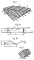
- Fig. 1 Shown in Fig. 1 is the principle of how three heat exchanger plates 1 a, 1 and 1 c, are stacked upon each other and offset 90° in relation to each other. This figure does not show the means of how the separate plates are connected with each other.
- Each plate is equipped with lengthwise distance members 2, devised as pleats in the plate. This results in the formation of extended rectangular flow passages designated 3a and 3b for the air which is thus made to pass in cross-current.
- the air flows are indicated by the arrows A and B, respectively.
- the width "b" (Fig. 2a) of the flow passages is between 10 to 50 mm, preferably between 20-30 mm, and their height "h" corresponding to the pleat height of the distance members is greater than 1.5 mm, preferably 2-10 mm. It has been found that this form of flow passages is beneficial in view of heat transfer, pressure drop, strength and production technology.
- the plates of heat exchanger are made of aluminium material.
- the plates are equipped with a friction pressure drop forming fine structure 4 in the form of corrugations as shown in Fig. 2a and 2b.
- the corrugations are preferably arranged at right angles to the distance members.
- the distance members can be designed with a fine structure.
- the design of the fine structure in greater detail is demonstrated by the schematic Fig. 2b which shows a cross-section of a contact plate.
- the corrugations of the fine structure display a pleat height S which amounts to between 0.1 and 1 mm.
- the fine structure of the plate 1b has a wavelength v of between 1 and 5 mm, preferably 3 mm, and its shape is triangular as indicated in the figure. The shape may also be sinusoidal or some interlying shape.
- a fine structural plate has a material thickness (t) of less than 0.1 mm, and the fine structural thickness (T) of the plates, defined as the total thickness of the plate areas with undeformed fine structure (4), i.e., S plus t, amounts to 0.1 and 1 mm, preferably 0.5 mm.
- Fig. 2a Shown in detail and schematically in Fig. 2a is an end view of two heat exchanger plates 1a and 1b. Formed between two distance members 2 in the lower plate and the upper plate is the air flow passage 3 which is thus shown in cross-section.
- the sides 5a and 5b of the distance members 2 are according to one embodiment pressed together towards each other to form a small gap 6 at the underside of the plate.
- One effect of the gap 6 is that it contributes towards some generation of turbulence in the air on the underside of the plate, which is sufficient to increase the heat transfer coefficient, but only contributes to a minor extent towards an increase of the pressure drop in the flow passage.
- the fine structure of the plate 1 has a wavelength v of between 2-5 mm, preferably 3 mm, and its shape is sinusoidal as shown in the figure.
- the shap e may also be triangular or some interlying shape.
- FIG. 3 Shown in Fig. 3 is how a plurality of exchanger plates are combined into a heat exchanger package.
- the heat exchanger package is usually arranged so that the heat exchanger plates are disposed vertically.
- the heat exchanger body is inclined towards the horizontal plane to facilitate discharge of condensate water precipitated in the flow passage.
- Fig. 4, 5a and 5b as well as 6 show in detail how a bottom heat exchanger plate according to the invention is connected at its end edge with a top heat exchanger plate.
- a necessity for the heat exchanger package to function properly is that the plates are joined effectively, both from a mechanical and a sealing point of view. A leakage between the separated flow passages should be avoided as far as possible and may in some applications prove definitely harmful.
- Fig. 6 shows how the heat exchanger plate terminating across the distance members at its two end sides 10a, b displays a lengthwise section of end zones 11a, b.
- Each contact plate also displays at its two end sides 20a, b terminating along the distance members, a lengthwise section 21a, b, in which a folding edge 22a, b is arranged.
- the plate displays the notches 26.
- the edges 22a, b are intended to be joined with an adjacent plate in such a way that they will be folded around the adjacent edge zone area, by which a folded edge 23 is formed.
- the folding edge 22a, 22b displays a distance section 25 which by its size corresponds to the distance between the adjacent plates determined by the pleat height, and forms a seal of the side for the corresponding flow passages 3a, 3b at the ends of the plates.
- the folded edge 23 extends over the corresponding edge zone area and encloses this.
- the edge 23 and the enclosing material also display a lengthwise pleating 24 which extends along the whole width of the plate and is designed to achieve locking of the edge 23 and, if necessary, thus prevent the folding edge 22a, b from springing back.
- the fine structure in the pleating of the two plates is partly deformed owing to their being pressed together and forms an effective seal between the plates. In effect, the thickness resulting from the compression is not larger than the plate thickness T defined in Figure 2b.
- An especially purposeful embodiment according to the invention is the arrangement of down- folding the distance member, as shown in Fig. 5a, and then covering from the underlying plate it by the edge 23.
- the fine structure of the plates stacked upon each other including the folding edge 22a, b and the edge 23) has been deformed so that the common thickness, on the whole, still is enclosed in the plate thickness T, as defined in the Figure 2b.
- This condition can be accomplished also when both sides 5a, 5b of the distance members 2 are provided with a fine structure.
- the pleating 24 displays according the invention a wavelength Y and a waveheight y which are dimensioned so that they give rise to a stretching of the material that at least corresponds to the surface expansion ensuing from the deformation of the fine structure in the pleating.
- the wavelength Y of the pleating amounts to about 10 mm and its waveheight y to about 2 mm.
- the surface expansion of the fine structure amounts to between 1% and 10%, preferably 3%.
- a very effective seal between the separate flow passages is achieved by this method.
- the stretching of the folded edge 23 brought about (effected) by the lengthwise pleating 24 smoothes out the fine structure of the edge 23 and renders a pleated, smooth and tight joint.
- the downfolded distance members 2 can be enclosed in thickness T of the plates thanks to the fine structure.
- the shown embodiment of the plate heat exchanger is intended in the first instance for application in comfort ventilation plants, but obviously the invention is not limited to this embodiment.
Landscapes
- Engineering & Computer Science (AREA)
- Physics & Mathematics (AREA)
- Thermal Sciences (AREA)
- Mechanical Engineering (AREA)
- General Engineering & Computer Science (AREA)
- Heat-Exchange Devices With Radiators And Conduit Assemblies (AREA)
- Cooling Or The Like Of Semiconductors Or Solid State Devices (AREA)
- Moulds For Moulding Plastics Or The Like (AREA)
- Table Devices Or Equipment (AREA)
Claims (14)
Priority Applications (1)
| Application Number | Priority Date | Filing Date | Title |
|---|---|---|---|
| AT84116425T ATE41228T1 (de) | 1983-12-29 | 1984-12-28 | Plattenwaermetauscher. |
Applications Claiming Priority (4)
| Application Number | Priority Date | Filing Date | Title |
|---|---|---|---|
| SE8307215A SE8307215L (sv) | 1983-12-29 | 1983-12-29 | Plattvermevexlare |
| SE8307215 | 1983-12-29 | ||
| SE8404845 | 1984-09-27 | ||
| SE8404845A SE8404845L (sv) | 1983-12-29 | 1984-09-27 | Plattvermevexlare |
Publications (3)
| Publication Number | Publication Date |
|---|---|
| EP0147866A2 EP0147866A2 (de) | 1985-07-10 |
| EP0147866A3 EP0147866A3 (en) | 1985-11-06 |
| EP0147866B1 true EP0147866B1 (de) | 1989-03-08 |
Family
ID=26658606
Family Applications (1)
| Application Number | Title | Priority Date | Filing Date |
|---|---|---|---|
| EP19840116425 Expired EP0147866B1 (de) | 1983-12-29 | 1984-12-28 | Plattenwärmetauscher |
Country Status (5)
| Country | Link |
|---|---|
| EP (1) | EP0147866B1 (de) |
| DE (1) | DE3477052D1 (de) |
| DK (1) | DK160587C (de) |
| FI (1) | FI78983C (de) |
| NO (1) | NO162312C (de) |
Cited By (1)
| Publication number | Priority date | Publication date | Assignee | Title |
|---|---|---|---|---|
| USD300771S (en) | 1984-09-27 | 1989-04-18 | Flakt Aktiebolag | Plate heat exchanger |
Families Citing this family (2)
| Publication number | Priority date | Publication date | Assignee | Title |
|---|---|---|---|---|
| US20130048261A1 (en) * | 2011-08-26 | 2013-02-28 | Hs Marston Aerospace Ltd. | Heat exhanger |
| CN105202960A (zh) * | 2015-10-10 | 2015-12-30 | 安陆火凤凰铝材有限责任公司 | 一种铝管式换热器 |
Family Cites Families (9)
| Publication number | Priority date | Publication date | Assignee | Title |
|---|---|---|---|---|
| GB510197A (en) * | 1938-02-18 | 1939-07-28 | Charles Otto Wagner | Improvements relating to sheet metal heat interchanging apparatus for fluids |
| GB510206A (en) * | 1938-03-17 | 1939-07-28 | Charles Otto Wagner | Improvements relating to heat interchange apparatus of the metal sheet or strip typefor fluids |
| SE127755C1 (sv) * | 1945-05-28 | 1950-03-28 | Ljungstroms Angturbin Ab | Elementsats för värmeväxlare |
| US3893509A (en) * | 1974-04-08 | 1975-07-08 | Garrett Corp | Lap joint tube plate heat exchanger |
| CH588672A5 (de) * | 1975-07-11 | 1977-06-15 | Alusuisse | |
| SE7508256L (sv) * | 1975-07-18 | 1977-01-19 | Munters Ab Carl | Sett att framstella en vermevexlarkorpp for rekuperativa vexlare |
| SE423750B (sv) * | 1977-01-14 | 1982-05-24 | Munters Ab Carl | Anordning vid vermevexlare for sensibel och/eller latent vermeoverforing |
| DE2953392C2 (de) * | 1979-08-23 | 1984-12-13 | Hisaka Works Ltd., Osaka | Plattenförmiger Wärmeaustauscher |
| US4298061A (en) * | 1980-08-15 | 1981-11-03 | The Singer Company | Heat exchanger with crimped flange seam |
-
1984
- 1984-12-21 DK DK622484A patent/DK160587C/da active
- 1984-12-28 NO NO845268A patent/NO162312C/no not_active IP Right Cessation
- 1984-12-28 EP EP19840116425 patent/EP0147866B1/de not_active Expired
- 1984-12-28 DE DE8484116425T patent/DE3477052D1/de not_active Expired
- 1984-12-28 FI FI845151A patent/FI78983C/fi active IP Right Grant
Cited By (1)
| Publication number | Priority date | Publication date | Assignee | Title |
|---|---|---|---|---|
| USD300771S (en) | 1984-09-27 | 1989-04-18 | Flakt Aktiebolag | Plate heat exchanger |
Also Published As
| Publication number | Publication date |
|---|---|
| FI845151L (fi) | 1985-06-30 |
| NO162312C (no) | 1989-12-06 |
| NO162312B (no) | 1989-08-28 |
| NO845268L (no) | 1985-07-01 |
| DK160587C (da) | 1991-09-09 |
| DE3477052D1 (en) | 1989-04-13 |
| FI78983C (fi) | 1989-10-10 |
| DK160587B (da) | 1991-03-25 |
| DK622484D0 (da) | 1984-12-21 |
| EP0147866A3 (en) | 1985-11-06 |
| FI78983B (fi) | 1989-06-30 |
| EP0147866A2 (de) | 1985-07-10 |
| FI845151A0 (fi) | 1984-12-28 |
| DK622484A (da) | 1985-06-30 |
Similar Documents
| Publication | Publication Date | Title |
|---|---|---|
| EP0829692B1 (de) | Wärmetauscher und Verfahren zur Herstellung eines Wärmetauschelements | |
| US2959400A (en) | Prime surface heat exchanger with dimpled sheets | |
| US5996633A (en) | Heat-exchanging conduit tubes for laminated heat exchanger and method for producing same | |
| US2959401A (en) | Plate-fin type heat exchanger and method of making the same | |
| JP4584524B2 (ja) | 熱伝達プレートおよびプレート型熱交換器に用いるプレート充填体 | |
| US4858685A (en) | Plate-type heat exchanger | |
| US5685075A (en) | Method for brazing flat tubes of laminated heat exchanger | |
| US6742578B2 (en) | Heat exchanger core | |
| US5209289A (en) | Lanced ruffled turbulizer | |
| JP2000508751A (ja) | プレート熱交換器 | |
| US20030093900A1 (en) | Method for assembling the plates of a plate pack and resulting plate pack | |
| EP0183008A1 (de) | Plattenwärmetauscher | |
| CA2484856C (en) | Cross-over rib plate pair for heat exchanger | |
| CA1072077A (en) | Heat exchanger tube and method of making same | |
| KR20010015811A (ko) | 열교환기 | |
| JPH08219677A (ja) | 熱交換器としてのプレート積層体 | |
| EP0745821B1 (de) | Verfahren zur Herstellung eines Wärmetauschers mit abgeteilter Endkammer | |
| EP0984239A2 (de) | Wärmetauscher | |
| EP0147866A2 (de) | Plattenwärmetauscher | |
| EP0984238B1 (de) | Wärmetauscher | |
| CN214502199U (zh) | 一种原表面式换热器芯体 | |
| GB2183811A (en) | Rotary regenerative heat exchanger | |
| US6374904B1 (en) | Heat exchanger and channel member therefor | |
| JP4369223B2 (ja) | 熱交換器用エレメント | |
| CN101089535A (zh) | 端面成形密封的板式热交换器 |
Legal Events
| Date | Code | Title | Description |
|---|---|---|---|
| PUAI | Public reference made under article 153(3) epc to a published international application that has entered the european phase |
Free format text: ORIGINAL CODE: 0009012 |
|
| AK | Designated contracting states |
Designated state(s): AT BE CH DE FR GB IT LI LU NL SE |
|
| PUAL | Search report despatched |
Free format text: ORIGINAL CODE: 0009013 |
|
| AK | Designated contracting states |
Designated state(s): AT BE CH DE FR GB IT LI LU NL SE |
|
| 17P | Request for examination filed |
Effective date: 19860318 |
|
| 17Q | First examination report despatched |
Effective date: 19860731 |
|
| D17Q | First examination report despatched (deleted) | ||
| ITF | It: translation for a ep patent filed | ||
| GRAA | (expected) grant |
Free format text: ORIGINAL CODE: 0009210 |
|
| AK | Designated contracting states |
Kind code of ref document: B1 Designated state(s): AT BE CH DE FR GB IT LI LU NL SE |
|
| REF | Corresponds to: |
Ref document number: 41228 Country of ref document: AT Date of ref document: 19890315 Kind code of ref document: T |
|
| REF | Corresponds to: |
Ref document number: 3477052 Country of ref document: DE Date of ref document: 19890413 |
|
| ET | Fr: translation filed | ||
| PGFP | Annual fee paid to national office [announced via postgrant information from national office to epo] |
Ref country code: AT Payment date: 19891214 Year of fee payment: 6 |
|
| ITTA | It: last paid annual fee | ||
| PG25 | Lapsed in a contracting state [announced via postgrant information from national office to epo] |
Ref country code: LU Free format text: LAPSE BECAUSE OF NON-PAYMENT OF DUE FEES Effective date: 19891231 |
|
| PGFP | Annual fee paid to national office [announced via postgrant information from national office to epo] |
Ref country code: NL Payment date: 19891231 Year of fee payment: 6 Ref country code: GB Payment date: 19891231 Year of fee payment: 6 |
|
| PGFP | Annual fee paid to national office [announced via postgrant information from national office to epo] |
Ref country code: CH Payment date: 19900103 Year of fee payment: 6 |
|
| PGFP | Annual fee paid to national office [announced via postgrant information from national office to epo] |
Ref country code: LU Payment date: 19900108 Year of fee payment: 6 |
|
| PLBE | No opposition filed within time limit |
Free format text: ORIGINAL CODE: 0009261 |
|
| STAA | Information on the status of an ep patent application or granted ep patent |
Free format text: STATUS: NO OPPOSITION FILED WITHIN TIME LIMIT |
|
| 26N | No opposition filed | ||
| PG25 | Lapsed in a contracting state [announced via postgrant information from national office to epo] |
Ref country code: GB Effective date: 19901228 Ref country code: AT Effective date: 19901228 |
|
| PG25 | Lapsed in a contracting state [announced via postgrant information from national office to epo] |
Ref country code: LI Effective date: 19901231 Ref country code: CH Effective date: 19901231 |
|
| PG25 | Lapsed in a contracting state [announced via postgrant information from national office to epo] |
Ref country code: NL Effective date: 19910701 |
|
| NLV4 | Nl: lapsed or anulled due to non-payment of the annual fee | ||
| GBPC | Gb: european patent ceased through non-payment of renewal fee | ||
| REG | Reference to a national code |
Ref country code: CH Ref legal event code: PL |
|
| EAL | Se: european patent in force in sweden |
Ref document number: 84116425.4 |
|
| PGFP | Annual fee paid to national office [announced via postgrant information from national office to epo] |
Ref country code: FR Payment date: 20001212 Year of fee payment: 17 |
|
| PGFP | Annual fee paid to national office [announced via postgrant information from national office to epo] |
Ref country code: DE Payment date: 20001218 Year of fee payment: 17 |
|
| PG25 | Lapsed in a contracting state [announced via postgrant information from national office to epo] |
Ref country code: DE Free format text: LAPSE BECAUSE OF NON-PAYMENT OF DUE FEES Effective date: 20020702 |
|
| PG25 | Lapsed in a contracting state [announced via postgrant information from national office to epo] |
Ref country code: FR Free format text: LAPSE BECAUSE OF NON-PAYMENT OF DUE FEES Effective date: 20020830 |
|
| REG | Reference to a national code |
Ref country code: FR Ref legal event code: ST |
|
| PGFP | Annual fee paid to national office [announced via postgrant information from national office to epo] |
Ref country code: BE Payment date: 20031223 Year of fee payment: 20 |
|
| PGFP | Annual fee paid to national office [announced via postgrant information from national office to epo] |
Ref country code: SE Payment date: 20031230 Year of fee payment: 20 |
|
| BE20 | Be: patent expired |
Owner name: *FLAKT A.B. Effective date: 20041228 |
|
| EUG | Se: european patent has lapsed | ||
| EUG | Se: european patent has lapsed |