EP0147880A2 - Mécanisme d'actionnement d'un frein à sabot pour véhicule ferroviaire - Google Patents
Mécanisme d'actionnement d'un frein à sabot pour véhicule ferroviaire Download PDFInfo
- Publication number
- EP0147880A2 EP0147880A2 EP84201739A EP84201739A EP0147880A2 EP 0147880 A2 EP0147880 A2 EP 0147880A2 EP 84201739 A EP84201739 A EP 84201739A EP 84201739 A EP84201739 A EP 84201739A EP 0147880 A2 EP0147880 A2 EP 0147880A2
- Authority
- EP
- European Patent Office
- Prior art keywords
- brake
- block holder
- actuator
- brake block
- leaf springs
- Prior art date
- Legal status (The legal status is an assumption and is not a legal conclusion. Google has not performed a legal analysis and makes no representation as to the accuracy of the status listed.)
- Granted
Links
Images

Classifications
-
- B—PERFORMING OPERATIONS; TRANSPORTING
- B61—RAILWAYS
- B61H—BRAKES OR OTHER RETARDING DEVICES SPECIALLY ADAPTED FOR RAIL VEHICLES; ARRANGEMENT OR DISPOSITION THEREOF IN RAIL VEHICLES
- B61H13/00—Actuating rail-vehicle brakes
- B61H13/20—Transmitting mechanisms
- B61H13/24—Transmitting mechanisms for cars with two axles or bogies with two axles and braking cylinder(s) for each bogie, the mechanisms at each side being interconnected
-
- B—PERFORMING OPERATIONS; TRANSPORTING
- B61—RAILWAYS
- B61H—BRAKES OR OTHER RETARDING DEVICES SPECIALLY ADAPTED FOR RAIL VEHICLES; ARRANGEMENT OR DISPOSITION THEREOF IN RAIL VEHICLES
- B61H13/00—Actuating rail-vehicle brakes
- B61H13/34—Details
- B61H13/38—Suspension of transmitting mechanisms
-
- B—PERFORMING OPERATIONS; TRANSPORTING
- B61—RAILWAYS
- B61H—BRAKES OR OTHER RETARDING DEVICES SPECIALLY ADAPTED FOR RAIL VEHICLES; ARRANGEMENT OR DISPOSITION THEREOF IN RAIL VEHICLES
- B61H1/00—Applications or arrangements of brakes with a braking member or members co-operating with the periphery of the wheel rim, a drum or the like
- B61H1/003—Applications or arrangements of brakes with a braking member or members co-operating with the periphery of the wheel rim, a drum or the like with an actuator directly acting on a brake head
Definitions
- This invention relates to a rail vehicle block brake actuator with a brake block holder laterally movably suspended relative to the brake actuator so as to be movable laterally during braking together with an axially movable wheel to be braked, although the actuator itself is fixedly mounted, whereby hangers suspending the brake block holder consist of leaf springs, preferably a stack of several springs at each side of the brake block holder, pivoted to a part on the actuator and to the brake block holder, respectively.
- a block brake actuator normally a so called brake unit containing a brake cylinder and a slack adjuster, can conventionally be provided with a brake block holder suspended therefrom.
- the suspension by hangers or suspension links is such that the brake block holder (provided with brake blocks) can pivot in the plane of the actuator push rod to and fro braking engagement with a wheel to be braked.
- the actuator is to be fixedly mounted in a rail vehicle underframe or bogie in the vicinity of the wheel to be braked.
- the problem of braking an axially movable wheel by means of a fixedly mounted brake actuator may as known be solved in that the brake block holder is laterally movably suspended relative to the brake actuator.
- the hangers suspending the brake block holder can consist of leaf springs.
- the leaf springs are prestressed in a direction for compensating for the bias of the taper of the wheel tread which it is intended to engage.
- a flat bar is arranged at one side of one of the stacks of leaf springs along the major length thereof in order to keep the leaf springs straight in their rest position in spite of their prestress.
- Fig. I is a front view, sectioned in its uppermost part, of a first embodiment of a brake actuator with a brake block holder according to the invention
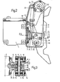
- Fig. 2 is a side view, partly sectioned along the lines II-II in Fig. 1
- Fig. 3 is a section along the lines III-III in Fig. 2.
- the bracket 2 is attached to the brake actuator 1 by means of screws 3.
- a brake block holder 4 is suspended in two hangers 5 pivotally attached to the bracket 2 at their respective upper ends and to the brake block holder 4 towards their lower ends.
- the outgoing push rod 6 of the brake actuator 1 (Fig. 3) is arranged to submit its pushing brake force to the brake block holder 4.
- the pivotal connection between the bracket 2 and the brake block hangers 5 has the following design:
- a cylindrical sleeve 7 has two radial flanges 7' and two trunnions 7" axially outside thereof.
- the hangers 5, each consisting of a stack of for example four leaf springs, are treaded over the trunnions 7" followed by a holder 8 at the right hand side as viewed in Fig. I and a longer flat bar 9 at the left hand side extending down towards the pivotal connection to the brake block holder 4.
- the whole arrangement at both sides is held together by screws 10.
- the arrangement 5, 7 - 10 thus formed is pivotally attached to the bracket 2 by means of a bushing 11, two end pieces 12, and a central screw 13.
- each hanger 5 is provided with a holder 14 at its outwardly facing side and a connection member 15 at its inwardly facing side, held together by screws 16.
- the connection with the brake block holder 4 is accomplished by means of a through screw 17 surrounded by a distance holding bushing 18 and a force receiving member 19.
- connection member 15 has an extension 15' downwards with a conventional friction device 20 for the purpose of keeping the brake block holder 4 in a substantially vertical position or rather in the position afforded to it at the foregoing braking operation. Also, each connection member 15 has an arm 15" extending upwards. These arms 15" are interconnected by a pin 21 providing a lower attachment for a brake block holder return spring 22, whose upper end is attached to the bracket 2 near the connection to the hangers 5.
- a force transmitting member 23 which is pivotally attached to the push rod 6 for lateral movements substantially in the plane of Fig.3. Its end surface for cooperation with a plane surface of the force receiving member 19 is cylindrical with its center coinciding with the pivot center for the force transmitting member 23. In this way the brake block holder 4 will be fully movable in the lateral direction relative to the brake actuator I itself also during force transmission.
- the push rod itself (normally forming part of a slack adjuster built into the brake actuator) may be pivotally mounted in the brake actuator and be directly connected with the brake block holder movable therewith.
- a rubber bellows 24 attached to the brake actuator 1 and the force transmitting member 23 will prevent dust, dirt and the like from entering the actuator 1.
- the brake block holder 4 is to be provided with conventional brake blocks (not shown), which are to be replaced when worn out. These brake blocks are to brakingly engage the tread of a rail vehicle wheel 25, whose lateral position is indicated in dash-dotted lines in Fig. 1 in the normal or rest condition.
- the leaf springs constituting the hangers 5 are slightly prestressed to the left in Fig. 1 so as to compensate for the bias to the right accomplished by the normal taper of the wheel tread at braking.
- the hangers 5 will, however, be maintained in the shown vertical position also in the rest position by the flat bar 9.
- the wheel flange will accomplish a movement to the right of the brake block holder 4 against the force of the leaf springs of the hangers 5, but only until the right hand side holder 14 hits the side wall of the bracket 2.
- a brake actuator with a brake block holder according to the invention is especially well suited for the case (which is becoming increasingly usual) that the wheel-sets of a rail vehicle are movable to a considerable extent also in the axial direction.
- the brake actuator itself can be fixedly mounted to the vehicle underframe or bogie in the vicinity of the wheel to be braked, whereas the brake block holder (with its brake blocks) is allowed to follow the axial movements of the wheel-set during braking.
- the arrangement is somewhat asymmetric in that the flat bar 9 is placed at the same side of the brake block holder 4 as the flange of the wheel 25 and in that the springs of the hangers 5 are prestressed in the same direction.
- a similar arrangement placed at the opposite side of the vehicle has accordingly to be inverted.
Landscapes
- Engineering & Computer Science (AREA)
- Mechanical Engineering (AREA)
- Braking Arrangements (AREA)
Applications Claiming Priority (2)
| Application Number | Priority Date | Filing Date | Title |
|---|---|---|---|
| SE8307077A SE446709B (sv) | 1983-12-21 | 1983-12-21 | Klotsbromsaktuator for ett relsfordon |
| SE8307077 | 1983-12-21 |
Publications (3)
| Publication Number | Publication Date |
|---|---|
| EP0147880A2 true EP0147880A2 (fr) | 1985-07-10 |
| EP0147880A3 EP0147880A3 (en) | 1985-08-07 |
| EP0147880B1 EP0147880B1 (fr) | 1987-07-22 |
Family
ID=20353838
Family Applications (1)
| Application Number | Title | Priority Date | Filing Date |
|---|---|---|---|
| EP84201739A Expired EP0147880B1 (fr) | 1983-12-21 | 1984-11-27 | Mécanisme d'actionnement d'un frein à sabot pour véhicule ferroviaire |
Country Status (8)
| Country | Link |
|---|---|
| US (1) | US4630714A (fr) |
| EP (1) | EP0147880B1 (fr) |
| JP (1) | JPS60154953A (fr) |
| KR (1) | KR920005594B1 (fr) |
| DE (1) | DE3464869D1 (fr) |
| ES (1) | ES294890Y (fr) |
| SE (1) | SE446709B (fr) |
| ZA (1) | ZA849946B (fr) |
Cited By (5)
| Publication number | Priority date | Publication date | Assignee | Title |
|---|---|---|---|---|
| EP0503723A3 (en) * | 1991-03-11 | 1992-11-19 | Sab Wabco Holdings B.V. | A rail vehicle brake actuator with a brake block holder |
| EP0503724A3 (en) * | 1991-03-11 | 1992-11-19 | Sab Wabco Holdings B.V. | A rail vehicle brake actuator with a brake block holder |
| EP0665152A1 (fr) * | 1994-02-01 | 1995-08-02 | Knorr-Bremse Systeme für Schienenfahrzeuge GmbH | Unité de freinage à sabot pour véhicules ferroviaires |
| FR2782303A1 (fr) | 1998-05-06 | 2000-02-18 | Knorr Bremse Systeme | Unite de frein a sabot pour vehicules sur rails |
| EP3536578A1 (fr) * | 2011-04-06 | 2019-09-11 | Faiveley Transport Nordic AB | Actionneur de frein de véhicule ferroviaire doté de moyens de transmission |
Families Citing this family (5)
| Publication number | Priority date | Publication date | Assignee | Title |
|---|---|---|---|---|
| SE466906B (sv) * | 1989-04-27 | 1992-04-27 | Wabco Holdings Sab | Bromsklotshaallararrangemang |
| SE468085B (sv) * | 1991-03-11 | 1992-11-02 | Wabco Holdings Sab | Tryckkraftoeverfoerande anordning vid en bromsaktuator |
| US8360214B2 (en) * | 2009-04-09 | 2013-01-29 | Wabtec Holding Corp. | Brake shoe support assembly and method |
| KR102204772B1 (ko) | 2020-09-03 | 2021-01-19 | 농업회사법인 보경팜테크 주식회사 | 과수 반사필름의 고정장치 |
| FR3129353B1 (fr) * | 2021-11-24 | 2023-11-24 | Faiveley Transp Amiens | Système de freinage ferroviaire pour véhicule ferroviaire, à freins à au moins un sabot, et véhicule ferroviaire pourvu d’un tel système |
Family Cites Families (7)
| Publication number | Priority date | Publication date | Assignee | Title |
|---|---|---|---|---|
| GB401402A (en) * | 1932-06-14 | 1933-11-16 | Alfred Walter Maley | Improvements in and relating to brake mechanism for rail vehicles |
| US2820625A (en) * | 1953-11-20 | 1958-01-21 | Foxboro Co | Pre-stressed instrument arm |
| CH330953A (de) * | 1954-03-08 | 1958-06-30 | Hartmann & Braun Ag | Stossdämpfendes Lager für feinmechanische Systeme |
| US3565219A (en) * | 1969-01-02 | 1971-02-23 | North American Rockwell | Flexible mount for a loom letoff brake |
| US3727900A (en) * | 1971-03-09 | 1973-04-17 | Fema Corp | Adjustable non-linear spring and spring suspension system |
| SE7810162L (sv) * | 1978-09-28 | 1980-03-29 | Sab Ind Ab | Monteringsarrangemang for en bromsaktuator pa ett relsfordon |
| US4406444A (en) * | 1981-06-19 | 1983-09-27 | General Signal Corporation | Brake hanger for railway brakes |
-
1983
- 1983-12-21 SE SE8307077A patent/SE446709B/sv not_active IP Right Cessation
-
1984
- 1984-11-27 DE DE8484201739T patent/DE3464869D1/de not_active Expired
- 1984-11-27 EP EP84201739A patent/EP0147880B1/fr not_active Expired
- 1984-12-06 US US06/678,834 patent/US4630714A/en not_active Expired - Fee Related
- 1984-12-12 JP JP59260954A patent/JPS60154953A/ja active Granted
- 1984-12-18 KR KR1019840008062A patent/KR920005594B1/ko not_active Expired
- 1984-12-20 ZA ZA849946A patent/ZA849946B/xx unknown
- 1984-12-20 ES ES1984294890U patent/ES294890Y/es not_active Expired
Cited By (6)
| Publication number | Priority date | Publication date | Assignee | Title |
|---|---|---|---|---|
| EP0503723A3 (en) * | 1991-03-11 | 1992-11-19 | Sab Wabco Holdings B.V. | A rail vehicle brake actuator with a brake block holder |
| EP0503724A3 (en) * | 1991-03-11 | 1992-11-19 | Sab Wabco Holdings B.V. | A rail vehicle brake actuator with a brake block holder |
| EP0665152A1 (fr) * | 1994-02-01 | 1995-08-02 | Knorr-Bremse Systeme für Schienenfahrzeuge GmbH | Unité de freinage à sabot pour véhicules ferroviaires |
| FR2782303A1 (fr) | 1998-05-06 | 2000-02-18 | Knorr Bremse Systeme | Unite de frein a sabot pour vehicules sur rails |
| DE19820199C1 (de) * | 1998-05-06 | 2000-02-24 | Knorr Bremse Systeme | Klotzbremseinheit für Schienenfahrzeuge |
| EP3536578A1 (fr) * | 2011-04-06 | 2019-09-11 | Faiveley Transport Nordic AB | Actionneur de frein de véhicule ferroviaire doté de moyens de transmission |
Also Published As
| Publication number | Publication date |
|---|---|
| KR920005594B1 (ko) | 1992-07-09 |
| ZA849946B (en) | 1985-08-28 |
| KR850004217A (ko) | 1985-07-11 |
| EP0147880B1 (fr) | 1987-07-22 |
| JPH0462903B2 (fr) | 1992-10-08 |
| SE8307077D0 (sv) | 1983-12-21 |
| ES294890U (es) | 1986-10-16 |
| ES294890Y (es) | 1987-07-01 |
| DE3464869D1 (en) | 1987-08-27 |
| EP0147880A3 (en) | 1985-08-07 |
| US4630714A (en) | 1986-12-23 |
| SE446709B (sv) | 1986-10-06 |
| JPS60154953A (ja) | 1985-08-14 |
| SE8307077L (sv) | 1985-06-22 |
Similar Documents
| Publication | Publication Date | Title |
|---|---|---|
| EP0147880B1 (fr) | Mécanisme d'actionnement d'un frein à sabot pour véhicule ferroviaire | |
| US4393962A (en) | Self-centering device for caliper brake assembly | |
| EP0046619B1 (fr) | Installation de frein à disque pour véhicules ferroviaires | |
| GB2055079A (en) | Rail traction vehicles | |
| CZ280346B6 (cs) | Otočný podvozek pro rychlá kolejová vozidla | |
| US2374777A (en) | Railway truck structure | |
| CA2314282C (fr) | Systeme de suspension pour ensemble de freinage d'une automobile | |
| EP0018050B2 (fr) | Fixation pour un sabot de frein ferroviaire | |
| KR880001162B1 (ko) | 철도차량의 롤 안정성 증가장치 | |
| EP0503723B1 (fr) | Moteur de frein d'un véhicule ferroviaire avec un support de patin de frein | |
| US4632422A (en) | Anti-roll torsion bar (stabilizer) for the running gear of vehicles | |
| EP0091151A1 (fr) | Etrier de frein à disque pour véhicule sur rail | |
| EP0503724A2 (fr) | Moteur de frein d'un véhicule ferroviaire avec un support de patin de frein | |
| JP2622036B2 (ja) | 電動軌道車用の連結2ヘッド付きパンタグラフ | |
| EP0077586B1 (fr) | Fixation pour un sabot de frein ferroviaire | |
| CA1176579A (fr) | Bride de suspension pour freins de chemins de fer | |
| AU647590B2 (en) | A brake assembly | |
| US3696892A (en) | Brake head-centering device for railway brake apparatus | |
| WO1980000682A1 (fr) | Systeme de montage pour un dispositif d'actionnement de frein d'un vehicule sur rail | |
| RU2039677C1 (ru) | Механическая часть тормоза железнодорожного грузового вагона бункерного типа | |
| DE19642984C1 (de) | Pendelaufhängung für Magnetschienenbremsen | |
| SU846357A1 (ru) | Устройство изменени тормозногоуСили B зАВиСиМОСТи OT НАгРузКижЕлЕзНОдОРОжНОгО ТРАНСпОРТНОгОСРЕдСТВА КОНыКА г.п. | |
| KR850000816B1 (ko) | 철도차량의 브레이크 블록홀드 | |
| SU1172798A1 (ru) | Стабилизатор тормозной рычажной передачи рельсового транспортного средства | |
| JPS57198105A (en) | Windup preventive mechanism in equalizer suspension |
Legal Events
| Date | Code | Title | Description |
|---|---|---|---|
| PUAI | Public reference made under article 153(3) epc to a published international application that has entered the european phase |
Free format text: ORIGINAL CODE: 0009012 |
|
| PUAL | Search report despatched |
Free format text: ORIGINAL CODE: 0009013 |
|
| AK | Designated contracting states |
Designated state(s): DE FR GB IT |
|
| AK | Designated contracting states |
Designated state(s): DE FR GB IT |
|
| 17P | Request for examination filed |
Effective date: 19860203 |
|
| 17Q | First examination report despatched |
Effective date: 19860917 |
|
| ITF | It: translation for a ep patent filed | ||
| GRAA | (expected) grant |
Free format text: ORIGINAL CODE: 0009210 |
|
| AK | Designated contracting states |
Kind code of ref document: B1 Designated state(s): DE FR GB IT |
|
| REF | Corresponds to: |
Ref document number: 3464869 Country of ref document: DE Date of ref document: 19870827 |
|
| ET | Fr: translation filed | ||
| PLBE | No opposition filed within time limit |
Free format text: ORIGINAL CODE: 0009261 |
|
| STAA | Information on the status of an ep patent application or granted ep patent |
Free format text: STATUS: NO OPPOSITION FILED WITHIN TIME LIMIT |
|
| 26N | No opposition filed | ||
| REG | Reference to a national code |
Ref country code: GB Ref legal event code: 732 |
|
| ITPR | It: changes in ownership of a european patent |
Owner name: CESSIONE;SAB WABCO HOLDINGS BV |
|
| REG | Reference to a national code |
Ref country code: FR Ref legal event code: TP Ref country code: FR Ref legal event code: CD |
|
| ITTA | It: last paid annual fee | ||
| PGFP | Annual fee paid to national office [announced via postgrant information from national office to epo] |
Ref country code: FR Payment date: 19961128 Year of fee payment: 13 |
|
| REG | Reference to a national code |
Ref country code: GB Ref legal event code: 732E |
|
| REG | Reference to a national code |
Ref country code: FR Ref legal event code: TP |
|
| PG25 | Lapsed in a contracting state [announced via postgrant information from national office to epo] |
Ref country code: FR Free format text: THE PATENT HAS BEEN ANNULLED BY A DECISION OF A NATIONAL AUTHORITY Effective date: 19971130 |
|
| REG | Reference to a national code |
Ref country code: FR Ref legal event code: ST |
|
| PGFP | Annual fee paid to national office [announced via postgrant information from national office to epo] |
Ref country code: GB Payment date: 20001109 Year of fee payment: 17 |
|
| PGFP | Annual fee paid to national office [announced via postgrant information from national office to epo] |
Ref country code: DE Payment date: 20010131 Year of fee payment: 17 |
|
| PG25 | Lapsed in a contracting state [announced via postgrant information from national office to epo] |
Ref country code: GB Free format text: LAPSE BECAUSE OF NON-PAYMENT OF DUE FEES Effective date: 20011127 |
|
| REG | Reference to a national code |
Ref country code: GB Ref legal event code: IF02 |
|
| PG25 | Lapsed in a contracting state [announced via postgrant information from national office to epo] |
Ref country code: DE Free format text: LAPSE BECAUSE OF NON-PAYMENT OF DUE FEES Effective date: 20020702 |
|
| GBPC | Gb: european patent ceased through non-payment of renewal fee |
Effective date: 20011127 |